
 Open Access Article
 This Open Access Article is licensed under a
 Creative Commons Attribution 3.0 Unported Licence
Design of electric field controlled molecular gates mounted on metal–organic frameworks†
Benjamin
Tam
and
Ozgur
Yazaydin
 *
*
Department of Chemical Engineering, University College London, Torrington Place, London, WC1E 7JE, UK. E-mail: ozgur.yazaydin@ucl.ac.uk
First published on 17th April 2017
Abstract
In this study we propose and computationally demonstrate the concept of electric field controlled molecular gates mounted on the open-metal coordination sites in metal–organic framework (MOF) materials. The MOF-molecular gate complex functions by opening and closing under the effect of an electric field. Our design involves Mg-MOF-74, a MOF with hexagonal channels with open-metal coordination sites at each corner, and a multifunctional gate molecule with permanent dipole which anchors itself on the host MOF material and responds to changes in the direction of an electric field by rotating around its backbone which acts as an axle. By carrying out density functional theory (DFT) calculations and molecular dynamics (MD) simulations we show that the MOF-molecular gate complex can be switched between two stable configurations, open and closed, by turning on and off an external electric field. We further show that the molecular gate can be controlled to block or allow the diffusion of methane molecules through the channels of the MOF like a nanoscale butterfly valve. Electric field controlled molecular gates mounted on MOFs can pave the way for new molecular machines and nanodevices which can store, deliver or select molecules on demand and with atomic precision.
Introduction
Molecular machines are supramolecular structures designed to transform external stimuli to coordinated collective mechanical movements which mimic those occurring at the macroscopic level.1,2 Examples of molecular machines are rotors,3 switches,4–6 gates,7,8 elevators,9,10 motors6,11–13 and tweezers,14 most of which were inspired by nature.15,16 More sophisticated designs include molecular machines which can move objects 10![[thin space (1/6-em)]](https://www.rsc.org/images/entities/char_2009.gif) 000 times greater than their mass17 and a molecular car.18,19 In the mid-1990s, Bedard et al.20 was the first to suggest the concept of electric field controlled molecular doorways by employing dipolar molecules. Later Zheng et al.21 synthesized a molecular rotor and characterized its response to an electric field by scanning tunnelling microscopy and barrier height imaging. Horinek et al.,22 Hsu et al.23 and Seldenthuis et al.24 reported molecular simulations of similar unidirectional rotational control of supramolecular machines by an electric field.
000 times greater than their mass17 and a molecular car.18,19 In the mid-1990s, Bedard et al.20 was the first to suggest the concept of electric field controlled molecular doorways by employing dipolar molecules. Later Zheng et al.21 synthesized a molecular rotor and characterized its response to an electric field by scanning tunnelling microscopy and barrier height imaging. Horinek et al.,22 Hsu et al.23 and Seldenthuis et al.24 reported molecular simulations of similar unidirectional rotational control of supramolecular machines by an electric field.
Another area developing rapidly, like molecular machines, and have harnessed great interest recently, is metal–organic frameworks (MOFs).25–29 MOFs are inorganic–organic hybrid porous crystalline materials formed by the self-assembly of metal ions and organic ligands via coordination bonds. In principal, with a judicious choice of the inorganic and the organic building blocks it is possible to fine tune the pore size and shape and chemical functionality of MOFs. Thanks to such versatility MOFs have been investigated for a wide range of applications, such as separations,30 gas storage,31,32 drug delivery,28,33,34 sensors,28,35,36 luminescence35,37 and catalyst.38–40 Structural and chemical properties of MOFs can also be tuned by post-synthesis modification.41–43 This is usually achieved by ligand functionalization or grafting molecules on open-metal coordination sites. The latter forms the basis of our study. By grafting ligands on open-metal coordination sites, majority of previous studies aimed at tuning the pore size and chemistry of MOFs for various separation and catalyst applications.43–50 More recently Stoddart and colleagues demonstrated the idea of positioning redox-active molecular switches within MOFs by grafting them on the open-metal coordination sites.51,52
Propelled by the advancement in both synthetic molecular machines and MOFs, here we propose to mount molecular gates on the open-metal sites of MOFs and control their opening and closing by utilizing changes in an electric field.20,21,23,24 The molecular gate consists of three basic features; anchors, a permanent dipole and an axle. The strong attraction provided by the open-metal coordination sites in MOFs provide anchoring points for the gate molecule and the permanent dipole allows the gate molecule to be influenced by an electric field and rotate around an axle to block or allow the diffusion of molecules in a channel. In our MOF-molecular gate design we first identified a MOF suitable for hosting a gate molecule. M-MOF-74 (M-CPO-27, M2-dhtp) (M = Mg, Ni, Co, Zn, Mn, Fe)54–56 materials have been studied for the adsorption of different species, including light gases and hydrocarbons.55,57–66 M-MOF-74 is composed of 2,5-dihydroxyterephthalate ligands and one of the named metal ions, forming a structure with hexagonal one-dimensional channels which are about 12 Å in size and bear a high density of open-metal coordination sites. The open-metal sites facing one another in M-MOF-74 provide anchoring points in order to mount the gate molecules and its one-dimensional channels are ideal for the demonstration of the gating effect; i.e. closing or opening the pore. Of particular interest to us is Mg-MOF-74 (Fig. 1a) due to the strong binding energies reported for various adsorbates.67,68
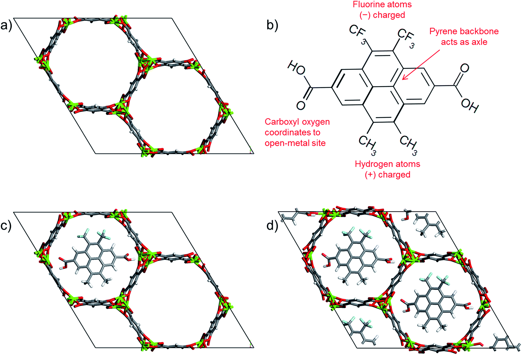 | ||
| Fig. 1 (a) Mg-MOF-74 unit cell, (b) chemical structure of the gate molecule, 4,5-dimethyl-9,10-bis(trifloromethyl)pyrene-2,7-dicarboxylic acid,53 (c) a molecular gate placed in one of the Mg-MOF-74 channels, and (d) MOF-molecular gate complex where all three channels of Mg-MOF-74 were occupied by the gate molecules. Carbon, oxygen, magnesium, fluorine and hydrogen are represented with grey, red, green, cyan and white, respectively. | ||
For the gate molecule, we considered 4,5-dimethyl-9,10-bis(trifloromethyl)pyrene-2,7-dicarboxylic acid (Fig. 1b). The carboxyl groups on both ends can coordinate to the open-metal sites thus anchoring the molecular gate. The central pyrene allows the molecule to rotate around an axle like a rotor. Finally, the negatively charged fluorine groups and the positively charged methyl groups create a permanent dipole which enables the molecule to respond changes in an electric field. Fig. 1c shows a molecular gate placed in one of the channels of Mg-MOF-74 and Fig. 1d shows all three channels of the Mg-MOF-74 occupied by the gate molecules.
Methods
DFT calculations
In order to assess the stability of a molecular gate mounted on Mg-MOF-74, we carried out DFT calculations. The crystal structure of Mg-MOF-74 was obtained from Cambridge Crystallographic Data Centre (CCDC).69 There are 162 atoms in a unit cell of Mg-MOF-74, and the unit cell dimensions and the angles are a = 25.873, b = 25.873, and c = 6.930 and α = 90.00, β = 90.00 and γ = 120.00, respectively. For the DFT calculations, Mg-MOF-74 unit cell was replicated 2 times in the z-direction to give a 1 × 1 × 2 structure. The gate was placed in one of the three channels of Mg-MOF-74 with the carboxyl groups positioned approximately 2.5 Å away from the magnesium atoms (Fig. 1c). The MOF-molecular gate complex was then geometry optimized (flexible cell) with periodic planewave DFT calculations using ultrasoft pseudopotentials with the CASTEP 16.1 software70 with the gate molecule at different rotational angles with respect to the x–y plane. Details of convergence criteria are given in Table S1.† The PBE functional71 with semi empirical dispersion corrections derived by Tkatchenko and Scheffler (DFT-D2)72 was used with the cut off energy and the k-point mesh set at 500 eV and 1 × 1 × 1, respectively. Binding energies of the gate molecule in the optimized configurations were calculated by subtracting the energies of the MOF and the gate from the energy of the MOF-molecular gate complex.MD simulations
MD simulations were carried out with the GROMACS73 software in order to investigate the effect of an external electric field on the molecular gates mounted on Mg-MOF-74.Because of the external electric field an additional force is exerted on the atoms due to partial charges. This force is calculated according to the following formula,
| F = qE |
Results and discussion
Closed (Fig. 2a) and open (Fig. 2b) configurations of the MOF-molecular gate complex with one gate molecule were optimized with periodic dispersion corrected DFT calculations. Binding energies of the gate molecule in the closed and open configurations were calculated as −357 kJ mol−1 and −278 kJ mol−1, respectively. These indicate that both the closed and open gate configurations are stable and the gate molecule binds to the MOF strongly. Furthermore, the MOF-molecular gate complex preserved the original hexagonal shape of the Mg-MOF-74 channels. For instance, for the closed gate configuration the cell dimensions and the angles showed small deviations with respect to the experimental values and changed from a = 25.873, b = 25.873, and c = 13.860 to a = 26.526, b = 26.345 and c = 13.861 Å, and from α = 90.00, β = 90.00 and γ = 120.00 to α = 90.30, β = 89.68 and γ = 121.16, respectively.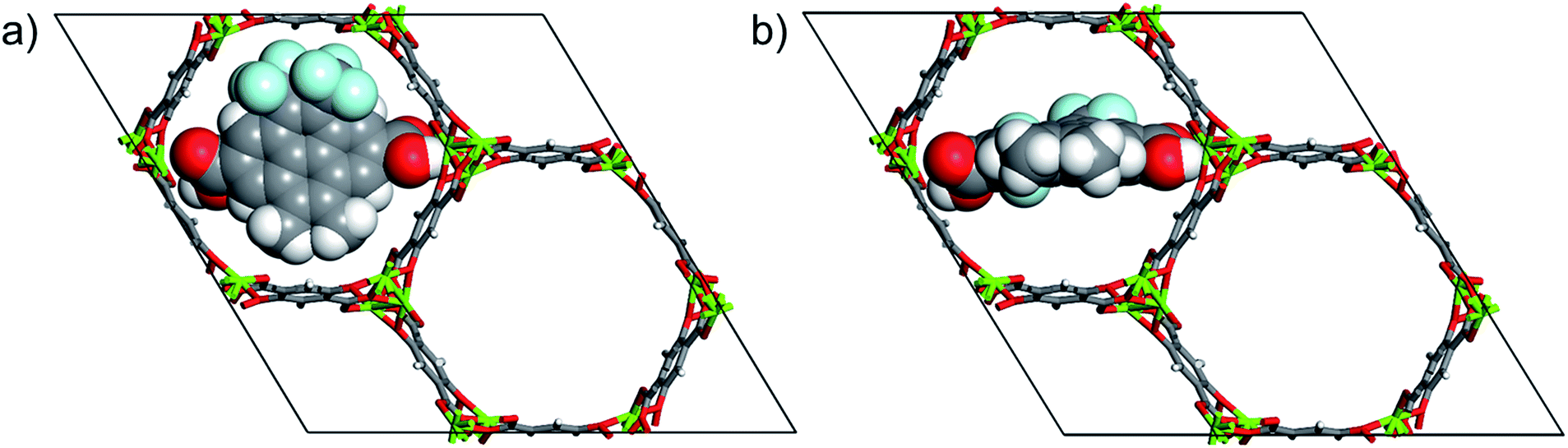 | ||
| Fig. 2 (a) DFT optimized closed gate configuration and (b) open gate configuration. Atom colours are same with those in Fig. 1. | ||
Fig. 3 shows the changes in the total energy of the complex obtained by DFT calculations with respect to the closed configuration as the molecular gate rotates until it reaches to the open configuration. Two rotational barriers were identified, one is 20 kJ mol−1 and located around 40 degrees, and the other one is 73 kJ mol−1 and located at 75 degrees. Closed and open configurations of the MOF-molecular gate complex with one-gate molecules were also optimized with classical MD simulations in the NPT ensemble. Binding energies of the molecular were −203 kJ mol−1 and −126 kJ mol−1 for the closed and open configurations, respectively. These values are lower than those obtained by the dispersion corrected DFT calculations; but still indicate the molecular gate is predicted to bind strongly to the MOF in classical MD simulations. The stability of the MOF-molecular gate complex with one gate molecule was further tested under increasing electric field strengths. It was found that the complex retained its structural integrity up to 8 V nm−1. On the other hand, the minimum electric field to overcome the intrinsic rotational barrier of a single molecular gate and bring it from the closed to open configuration was found to be 0.5 V nm−1. A system with all three channels occupied by molecular gates was also considered (Fig. 1d). Fig. 4 shows the total energy of this system with the electric field (3 V nm−1) turned on and off with consecutive periods of 1 ns. The simulation started with molecular gates at their closed configurations and run for 1 ns. Then the electric field was turned on in the z-direction for 1 ns during which the molecular gates switched to their open configurations. When the electric field was turned off for the next 1 ns, the molecular gates reverted back to their closed configurations. The energy difference between the closed and the open configurations was about 350 kJ mol−1.
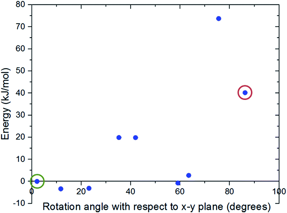 | ||
| Fig. 3 Energy variation of the MOF-molecular gate complex with the rotation of the gate molecule with respect to the x–y plane predicted by DFT calculations. The closed gate configuration, which was taken as the reference point, is circled with green and the open gate configuration with red. | ||
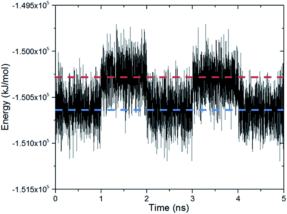 | ||
| Fig. 4 The energy of the MOF-molecular gate complex with all three channels occupied by the molecular gates form the MD simulation. An electric field with a 3 V nm−1 strength turned on and off with consecutive periods of 1 ns. The gate is at the closed configuration when the electric field is turned off (blue line) and at the open configuration when the electric field is turned on (red line). | ||
The complex with all three channels occupied by the molecular gates was further tested with methane molecules placed between the gates and the graphene wall in an NVT ensemble MD simulation (Fig. 5a). First, the system was simulated with the gate molecules in the closed configuration for 30 ns and no electric field was applied. The molecular gates resisted to rotation despite the pressure due to the presence of methane molecules (Fig. S1†) and remained in closed configuration as shown in Fig. 5a. During this period no methane molecules diffused to the empty pore volume behind the gates. This was visually confirmed and quantified with the number density of methane along the z-direction (Fig. 6a). Then the electric field in the z-direction was turned on (3 V nm−1) and the system was simulated for another 30 ns. With the electric field turned on, the molecular gates switched to open configuration (Fig. 5b) and the methane molecules diffused to the empty pore volume (Fig. 6b).
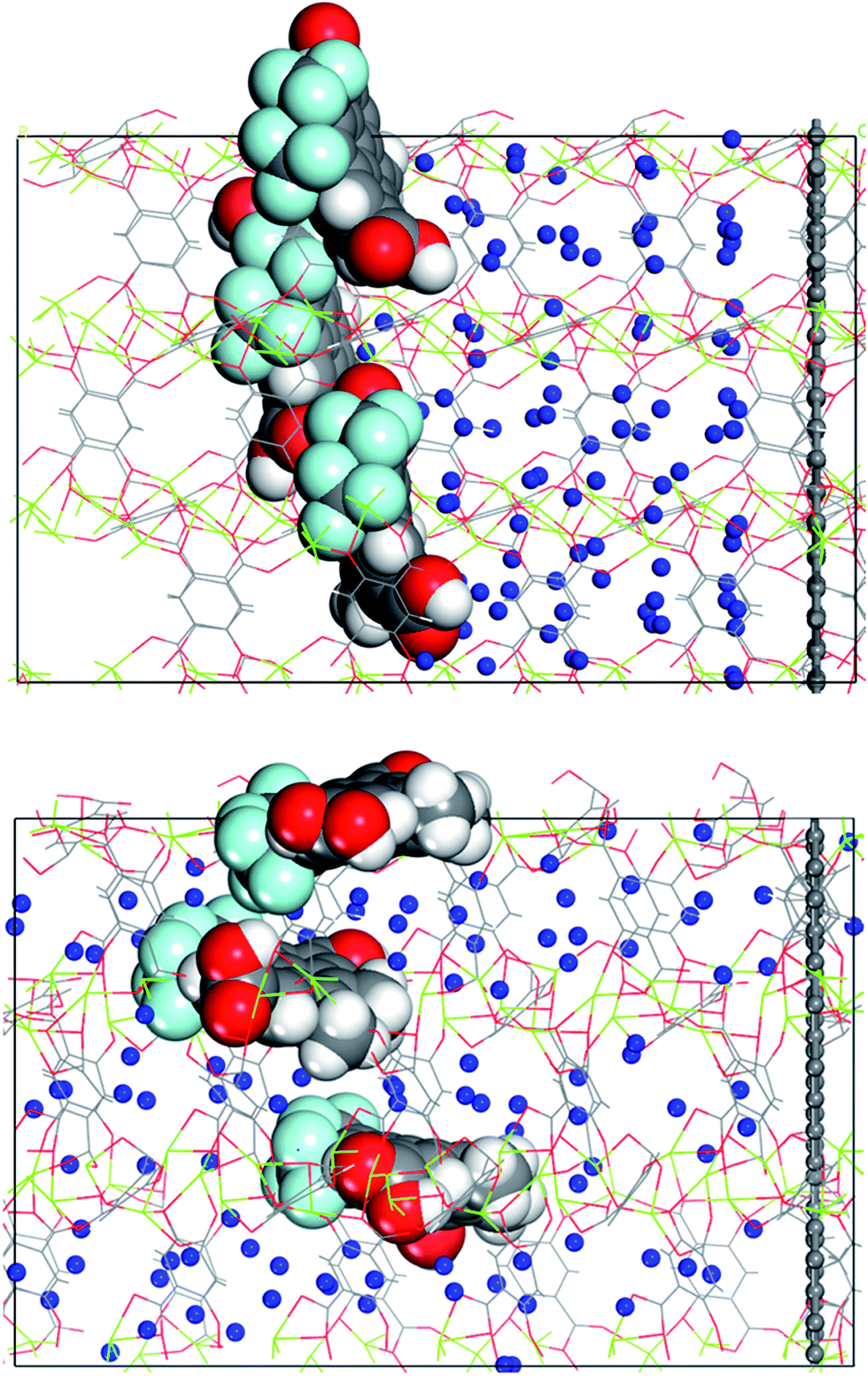 | ||
| Fig. 5 (a) Methane molecules placed between the molecular gates and the graphene wall, and (b) molecular gates switched to their open configurations and the methane molecules diffused towards the empty pore volume after the electric field was turned on. Methane molecules (blue), all other atom colours are same with those in Fig. 1. | ||
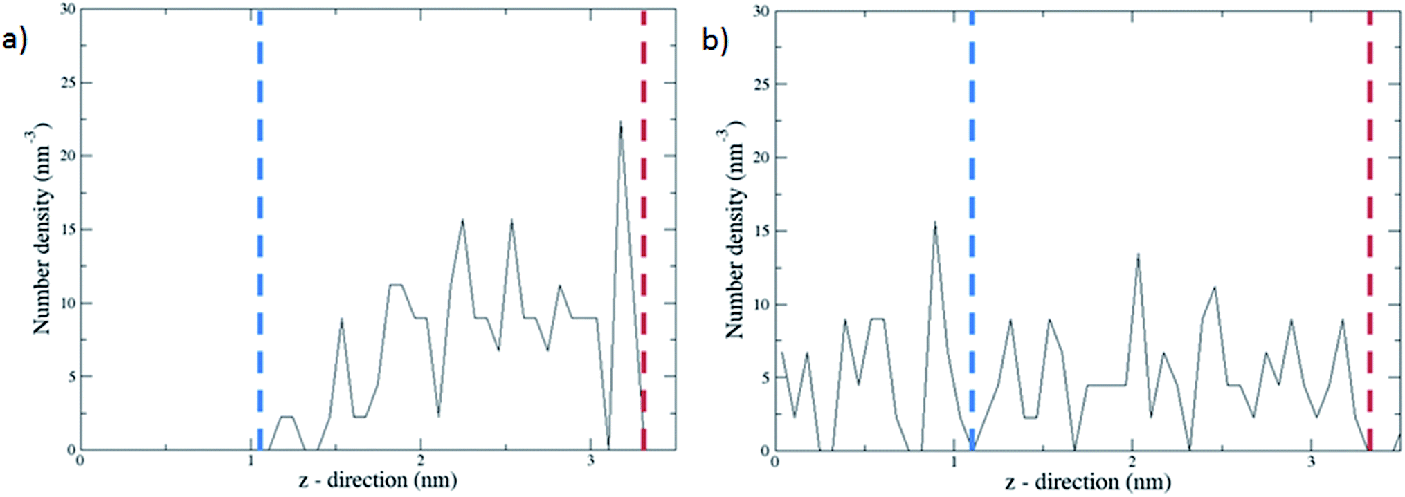 | ||
| Fig. 6 Number densities of methane along the z-direction averaged over 30 ns with the molecular gates are in (a) closed configuration and (b) open configuration. The blue and red dashed lines represent the positions of the gate molecules and the graphene wall, respectively. | ||
It should be noted that gate effects reported in the MOF literature are substantially different than the molecular gate concept we present in this study. Rather than involving a door type mechanism which opens and closes, previously reported gate effects were all based on either the reorientation of ligands or a shift in the topology of the structure, such that the pore volume decreased or increased up on exposure to external stimuli, e.g., gas adsorption or light.78–80 To the best of our knowledge, this is the first specific molecular gate design in MOFs dedicated to open and close the MOF pores for diffusion of molecules without the MOF undergoing any structural change. Overall, the MOF-molecular gate complex we designed resembles a butterfly valve mounted inside a pipe in order to regulate or prevent flow. By employing different functional groups it would be possible to adjust the electric field required to open or close this nanovalve. One could also imagine controlling the degree of opening of the valve by applying an electric field with different angles with respect to the x–y plane and thus regulating the flow rate.
We recognise that the synthesis of a device which integrates a MOF and a molecular gate responding to an external electric field is a daunting task. However, there have been recent reports of experimental work which demonstrated the incorporation of molecular machines in MOFs. Stoddard and colleagues51,52 mounted rotaxane and catenane based molecular switches on the open-metal coordination sites of NU-1000 MOF.81 Zhu et al. synthesized a molecular shuttle in the form of a crown-8 wheel which moved back and forth on the ligands of UWDM-4 MOF.82 The use of an electric field as an external stimulus has also been demonstrated. Zheng et al.21 used the tip of a scanning tunnelling microscope (STM) to create an electric field in order to switch the configuration of a fluorine functionalised phenanthrene molecular turnstile between two different stable positions. Remarkably, the strength of the electric field used in the study of Zheng et al., which was 1 V nm−1, compares very well with the range of electric field we used in our computational study. In another ground breaking study, again an STM tip was used to drag a molecular car over a distance of several nanometres.18 At the very least these experimental studies suggest that the incorporation of more complex molecular machines controlled by an external electric field in MOFs, or in other porous materials, such as the molecular gate we propose, can one day go beyond the level of conceptual design based on molecular simulations and become reality.
Conclusions
By taking advantage of open-metal coordination sites in MOFs we computationally designed a molecular gate mounted on MOFs. Mg-MOF-74, a MOF with hexagonal channels with open-metal coordination sites at each corner, was used as the host material. For the gate molecule 4,5-dimethyl-9,10-bis(trifloromethyl)pyrene-2,7-dicarboxylic acid was considered. This gate molecule has carboxyl groups to coordinate to the open-metal sites, a permanent dipole to respond to an electric field and a pyrene backbone to act as an axle. By carrying out dispersion corrected DFT calculations we showed that the gate molecule binds to the MOF strongly. MD simulations demonstrated that the gate molecules switch between two stable configurations, closed and open, by turning on and off an electric field. We then showed that this can be used to control the flow of methane molecules in the channels of Mg-MOF-74. The concept of electric field controlled molecular gates mounted on MOFs presented in this study can inspire the rational design of new molecular machines and nanodevices which can store, deliver and select molecules on demand and with atomic precision.Acknowledgements
B. J. acknowledges Engineering and Physical Sciences Research Council (EPSRC) for supporting graduate studies. O. Y. acknowledges financial support from Leverhulme Trust Grant RPG-2016-331.References
- W. R. Browne and B. L. Feringa, Nat. Nanotechnol., 2006, 1, 25–35 CrossRef CAS PubMed.
- J. Cao, M. C. T. Fyfe, J. F. Stoddart, G. R. L. Cousins and P. T. Glink, J. Org. Chem., 2000, 65, 1937–1946 CrossRef CAS PubMed.
- J. Conyard, K. Addison, I. A. Heisler, A. Cnossen, W. R. Browne, B. L. Feringa and S. R. Meech, Nat. Chem., 2012, 4, 547–551 CrossRef CAS PubMed.
- C. O. Dietrich-Buchecker, J. P. Sauvage and J. P. Kintzinger, Tetrahedron Lett., 1983, 24, 5095–5098 CrossRef CAS.
- P. L. Anelli, N. Spencer and J. F. Stoddart, J. Am. Chem. Soc., 1991, 113, 5131–5133 CrossRef CAS PubMed.
- N. Koumura, R. W. J. Zijlstra, R. A. van Delden, N. Harada and B. L. Feringa, Nature, 1999, 401, 152–155 CrossRef CAS PubMed.
- J. Seo, R. Matsuda, H. Sakamoto, C. Bonneau and S. Kitagawa, J. Am. Chem. Soc., 2009, 131, 12792–12800 CrossRef CAS PubMed.
- S. Muramatsu, K. Kinbara, H. Taguchi, N. Ishii and T. Aida, J. Am. Chem. Soc., 2006, 128, 3764–3769 CrossRef CAS PubMed.
- J. D. Badjić, V. Balzani, A. Credi, S. Silvi and J. F. Stoddart, Science, 2004, 303, 1845 CrossRef PubMed.
- J. D. Badjic, C. M. Ronconi, J. F. Stoddart, V. Balzani, S. Silvi and A. Credi, J. Am. Chem. Soc., 2006, 128, 1489–1499 CrossRef CAS PubMed.
- B. J. Dahl and B. P. Branchaud, Tetrahedron Lett., 2004, 45, 9599–9602 CrossRef CAS.
- R. A. van Delden, M. K. J. Ter Wiel, M. M. Pollard, J. Vicario, N. Koumura and B. L. Feringa, Nature, 2005, 437, 1337–1340 CrossRef CAS PubMed.
- N. Ruangsupapichat, M. M. Pollard, S. R. Harutyunyan and B. L. Feringa, Nat. Chem., 2011, 3, 53–60 CrossRef CAS PubMed.
- M. Lindqvist, K. Borre, K. Axenov, B. Kótai, M. Nieger, M. Leskelä, I. Pápai and T. Repo, J. Am. Chem. Soc., 2015, 137, 4038–4041 CrossRef CAS PubMed.
- S. Erbas-Cakmak, D. A. Leigh, C. T. McTernan and A. L. Nussbaumer, Chem. Rev., 2015, 115, 10081–10206 CrossRef CAS PubMed.
- E. R. Kay, D. A. Leigh and F. Zerbetto, Angew. Chem., Int. Ed., 2007, 46, 72–191 CrossRef CAS PubMed.
- R. Eelkema, M. M. Pollard, J. Vicario, N. Katsonis, B. S. Ramon, C. W. M. Bastiaansen, D. J. Broer and B. L. Feringa, Nature, 2006, 440, 163 CrossRef CAS PubMed.
- T. Kudernac, N. Ruangsupapichat, M. Parschau, B. Macia, N. Katsonis, S. R. Harutyunyan, K.-H. Ernst and B. L. Feringa, Nature, 2011, 479, 208–211 CrossRef CAS PubMed.
- A. V. Akimov and A. B. Kolomeisky, J. Phys. Chem. C, 2012, 116, 22595–22601 CAS.
- T. C. Bedard and J. S. Moore, J. Am. Chem. Soc., 1995, 117, 10662–10671 CrossRef CAS.
- X. Zheng, M. E. Mulcahy, D. Horinek, F. Galeotti, T. F. Magnera and J. Michl, J. Am. Chem. Soc., 2004, 126, 4540–4542 CrossRef CAS PubMed.
- D. Horinek and J. Michl, Proc. Natl. Acad. Sci. U. S. A., 2005, 102, 14175–14180 CrossRef CAS PubMed.
- L.-Y. Hsu, E. Y. Li and H. Rabitz, Nano Lett., 2013, 13, 5020–5025 CrossRef CAS PubMed.
- J. S. Seldenthuis, F. Prins, J. M. Thijssen and H. S. J. van der Zant, ACS Nano, 2010, 4, 6681–6686 CrossRef CAS PubMed.
- H. Li, M. Eddaoudi, M. O'Keeffe and O. M. Yaghi, Nature, 1999, 402, 276–279 CrossRef CAS.
- H.-C. Zhou and S. Kitagawa, Chem. Soc. Rev., 2014, 43, 5415–5418 RSC.
- J. R. Long and O. M. Yaghi, Chem. Soc. Rev., 2009, 38, 1213–1214 RSC.
- R. J. Kuppler, D. J. Timmons, Q.-R. Fang, J.-R. Li, T. A. Makal, M. D. Young, D. Yuan, D. Zhao, W. Zhuang and H.-C. Zhou, Coord. Chem. Rev., 2009, 253, 3042–3066 CrossRef CAS.
- H. Furukawa, K. E. Cordova, M. O'Keeffe and O. M. Yaghi, Science, 2013, 341, 1230444 CrossRef PubMed.
- S. Qiu, M. Xue and G. Zhu, Chem. Soc. Rev., 2014, 43, 6116–6140 RSC.
- L. Li, S. Tang, C. Wang, X. Lv, M. Jiang, H. Wu and X. Zhao, Chem. Commun., 2014, 50, 2304–2307 RSC.
- D. Alezi, Y. Belmabkhout, M. Suyetin, P. M. Bhatt, Ł. J. Weseliński, V. Solovyeva, K. Adil, I. Spanopoulos, P. N. Trikalitis, A.-H. Emwas and M. Eddaoudi, J. Am. Chem. Soc., 2015, 137, 13308–13318 CrossRef CAS PubMed.
- J. Zhuang, C.-H. Kuo, L.-Y. Chou, D.-Y. Liu, E. Weerapana and C.-K. Tsung, ACS Nano, 2014, 8, 2812–2819 CrossRef CAS PubMed.
- T. Kundu, S. Mitra, P. Patra, A. Goswami, D. Díaz Díaz and R. Banerjee, Chem.–Eur. J., 2014, 20, 10514–10518 CrossRef CAS PubMed.
- D. Ma, B. Li, X. Zhou, Q. Zhou, K. Liu, G. Zeng, G. Li, Z. Shi and S. Feng, Chem. Commun., 2013, 49, 8964–8966 RSC.
- J.-H. Wang, M. Li and D. Li, Chem. Sci., 2013, 4, 1793–1801 RSC.
- M.-J. Dong, M. Zhao, S. Ou, C. Zou and C.-D. Wu, Angew. Chem., Int. Ed., 2014, 53, 1575–1579 CrossRef CAS PubMed.
- A. Herbst, A. Khutia and C. Janiak, Inorg. Chem., 2014, 53, 7319–7333 CrossRef CAS PubMed.
- P. Garcia-Garcia, M. Muller and A. Corma, Chem. Sci., 2014, 5, 2979–3007 RSC.
- A. Dhakshinamoorthy and H. Garcia, Chem. Soc. Rev., 2014, 43, 5750–5765 RSC.
- Z. Wang and S. M. Cohen, Angew. Chem., 2008, 120, 4777–4780 CrossRef.
- Z. Wang and S. M. Cohen, Chem. Soc. Rev., 2009, 38, 1315–1329 RSC.
- B. Li, Y. Zhang, D. Ma, L. Li, G. Li, G. Li, Z. Shi and S. Feng, Chem. Commun., 2012, 48, 6151–6153 RSC.
- T. M. McDonald, D. M. D'Alessandro, R. Krishna and J. R. Long, Chem. Sci., 2011, 2, 2022–2028 RSC.
- A. Ö. Yazaydın, A. I. Benin, S. A. Faheem, P. Jakubczak, J. J. Low, R. R. Willis and R. Q. Snurr, Chem. Mater., 2009, 21, 1425–1430 CrossRef.
- S.-T. Zheng, X. Zhao, S. Lau, A. Fuhr, P. Feng and X. Bu, J. Am. Chem. Soc., 2013, 135, 10270–10273 CrossRef CAS PubMed.
- Y.-Y. Fu, C.-X. Yang and X.-P. Yan, Langmuir, 2012, 28, 6794–6802 CrossRef CAS PubMed.
- Y. K. Hwang, D.-Y. Hong, J.-S. Chang, S. H. Jhung, Y.-K. Seo, J. Kim, A. Vimont, M. Daturi, C. Serre and G. Férey, Angew. Chem., Int. Ed., 2008, 47, 4144–4148 CrossRef CAS PubMed.
- A. Torrisi, R. G. Bell and C. Mellot-Draznieks, Cryst. Growth Des., 2010, 10, 2839–2841 CAS.
- C. Zlotea, D. Phanon, M. Mazaj, D. Heurtaux, V. Guillerm, C. Serre, P. Horcajada, T. Devic, E. Magnier, F. Cuevas, G. Ferey, P. L. Llewellyn and M. Latroche, Dalton Trans., 2011, 40, 4879–4881 RSC.
- P. R. McGonigal, P. Deria, I. Hod, P. Z. Moghadam, A.-J. Avestro, N. E. Horwitz, I. C. Gibbs-Hall, A. K. Blackburn, D. Chen, Y. Y. Botros, M. R. Wasielewski, R. Q. Snurr, J. T. Hupp, O. K. Farha and J. F. Stoddart, Proc. Natl. Acad. Sci. U. S. A., 2015, 112, 11161–11168 CrossRef CAS PubMed.
- Q. Chen, J. Sun, P. Li, I. Hod, P. Z. Moghadam, Z. S. Kean, R. Q. Snurr, J. T. Hupp, O. K. Farha and J. F. Stoddart, J. Am. Chem. Soc., 2016, 138, 14242–14245 CrossRef CAS PubMed.
- G. P. Moss, Pure Appl. Chem., 1998, 70, 143 CrossRef CAS.
- E. D. Bloch, W. L. Queen, R. Krishna, J. M. Zadrozny, C. M. Brown and J. R. Long, Science, 2012, 335, 1606–1610 CrossRef CAS PubMed.
- T. Grant Glover, G. W. Peterson, B. J. Schindler, D. Britt and O. Yaghi, Chem. Eng. Sci., 2011, 66, 163–170 CrossRef CAS.
- W. Zhou, H. Wu and T. Yildirim, J. Am. Chem. Soc., 2008, 130, 15268–15269 CrossRef CAS PubMed.
- Z. Bao, L. Yu, Q. Ren, X. Lu and S. Deng, J. Colloid Interface Sci., 2011, 353, 549–556 CrossRef CAS PubMed.
- H. Wu, W. Zhou and T. Yildirim, J. Am. Chem. Soc., 2009, 131, 4995–5000 CrossRef CAS PubMed.
- T. Pham, K. A. Forrest, J. Eckert and B. Space, Cryst. Growth Des., 2016, 16, 867–874 CAS.
- T. Pham, K. A. Forrest, K. McLaughlin, J. Eckert and B. Space, J. Phys. Chem. C, 2014, 118, 22683–22690 CAS.
- A. L. Dzubak, L.-C. Lin, J. Kim, J. A. Swisher, R. Poloni, S. N. Maximoff, B. Smit and L. Gagliardi, Nat. Chem., 2012, 4, 810–816 CrossRef CAS PubMed.
- J. Liu, A. I. Benin, A. M. B. Furtado, P. Jakubczak, R. R. Willis and M. D. LeVan, Langmuir, 2011, 27, 11451–11456 CrossRef CAS PubMed.
- P. Verma, X. Xu and D. G. Truhlar, J. Phys. Chem. C, 2013, 117, 12648–12660 CAS.
- H. Kim, J. Park and Y. Jung, Phys. Chem. Chem. Phys., 2013, 15, 19644–19650 RSC.
- S. M. Chavan, G. C. Shearer, E. Bloch and S. Bordiga, ChemPhysChem, 2012, 13, 445–448 CrossRef CAS PubMed.
- D. Yu, A. O. Yazaydin, J. R. Lane, P. D. C. Dietzel and R. Q. Snurr, Chem. Sci., 2013, 4, 3544–3556 RSC.
- K. Yu, K. Kiesling and J. R. Schmidt, J. Phys. Chem. C, 2012, 116, 20480–20488 CAS.
- P. Canepa, C. A. Arter, E. M. Conwill, D. H. Johnson, B. A. Shoemaker, K. Z. Soliman and T. Thonhauser, J. Mater. Chem. A, 2013, 1, 13597–13604 CAS.
- W. L. Queen, M. R. Hudson, E. D. Bloch, J. A. Mason, M. I. Gonzalez, J. S. Lee, D. Gygi, J. D. Howe, K. Lee, T. A. Darwish, M. James, V. K. Peterson, S. J. Teat, B. Smit, J. B. Neaton, J. R. Long and C. M. Brown, Chem. Sci., 2014, 5, 4569–4581 RSC.
- J. Clark Stewart, D. Segall Matthew, J. Pickard Chris, J. Hasnip Phil, I. J. Probert Matt, K. Refson and C. Payne Mike, Z. Kristallogr., 2005, 220, 567 Search PubMed.
- J. P. Perdew, K. Burke and M. Ernzerhof, Phys. Rev. Lett., 1996, 77, 3865–3868 CrossRef CAS PubMed.
- A. Tkatchenko and M. Scheffler, Phys. Rev. Lett., 2009, 102, 073005 CrossRef PubMed.
- M. J. Abraham, T. Murtola, R. Schulz, S. Páll, J. C. Smith, B. Hess and E. Lindahl, SoftwareX, 2015, 1–2, 19–25 CrossRef.
- C. J. Casewit, K. S. Colwell and A. K. Rappe, J. Am. Chem. Soc., 1992, 114, 10035–10046 CrossRef CAS.
- J. J. Potoff and J. I. Siepmann, AIChE J., 2001, 47, 1676–1682 CrossRef CAS.
- C. Campañá, B. Mussard and T. K. Woo, J. Chem. Theory Comput., 2009, 5, 2866–2878 CrossRef PubMed.
- W. C. Swope, H. C. Andersen, P. H. Berens and K. R. Wilson, J. Chem. Phys., 1982, 76, 637–649 CrossRef CAS.
- D. Tanaka, K. Nakagawa, M. Higuchi, S. Horike, Y. Kubota, T. C. Kobayashi, M. Takata and S. Kitagawa, Angew. Chem., 2008, 120, 3978–3982 CrossRef.
- R. Lyndon, K. Konstas, A. W. Thornton, A. J. Seeber, B. P. Ladewig and M. R. Hill, Chem. Mater., 2015, 27, 7882–7888 CrossRef CAS.
- D. Fairen-Jimenez, S. A. Moggach, M. T. Wharmby, P. A. Wright, S. Parsons and T. Düren, J. Am. Chem. Soc., 2011, 133, 8900–8902 CrossRef CAS PubMed.
- J. E. Mondloch, W. Bury, D. Fairen-Jimenez, S. Kwon, E. J. DeMarco, M. H. Weston, A. A. Sarjeant, S. T. Nguyen, P. C. Stair, R. Q. Snurr, O. K. Farha and J. T. Hupp, J. Am. Chem. Soc., 2013, 135, 10294–10297 CrossRef CAS PubMed.
- K. Zhu, C. A. O'Keefe, V. N. Vukotic, R. W. Schurko and S. J. Loeb, Nat. Chem., 2015, 7, 514–519 CrossRef CAS PubMed.
Footnote |
| † Electronic supplementary information (ESI) available. See DOI: 10.1039/c7ta00101k |
| This journal is © The Royal Society of Chemistry 2017 |