 Open Access Article
Creative Commons Attribution 3.0 Unported Licence
A facile drop-casting approach to nanostructured copper oxide-painted conductive woven textile as binder-free electrode for improved energy storage performance in redox-additive electrolyte†
Sung Min
Cha
,
Goli
Nagaraju
,
S.
Chandra Sekhar
and
Jae Su
Yu
*
Department of Electronics and Radio Engineering, Institute for Wearable Convergence Electronics, Kyung Hee University, 1 Seocheon-dong, Giheung-gu, Yongin-si, Gyeonggi-do 446-701, Republic of Korea. E-mail: jsyu@khu.ac.kr; Fax: +82-31-206-2820; Tel: +82-31-201-3820
First published on 15th December 2016
Abstract
Hierarchical copper oxide (CuO) nanostructures (NSs) with caterpillar-like morphologies were facilely integrated onto a highly flexible conductive woven textile substrate (CWTs) by a drop-casting approach. Initially, the CuO NSs were synthesized via a simple and green wet-chemical method in 30 min and the obtained colloidal solution of CuO was easily dropped onto well-cleaned CWTs. By virtue of their interesting structural features, the caterpillar-like CuO NSs on CWTs were employed as binder-free electrodes for supercapacitors and their electrochemical properties were investigated in 1 M KOH solution. Additionally, a small portion of redox-additive potassium ferricyanide (K3Fe(CN)6) was added to the 1 M KOH solution, which led to efficient enhancement of energy storage performance with superior cycling stability for the caterpillar-like CuO NSs on CWTs. Furthermore, the fabricated asymmetric supercapacitor (SC) with CuO NSs on CWTs and activated carbon with an operating potential window of 1.5 V simultaneously exhibited excellent energy density and power density values. Such a simple and low-cost approach to easily construct metal oxide nanomaterials on flexible textiles with redox-additive electrolyte may be useful for several potential applications in high-performance energy storage devices.
Introduction
Recent advances in the development of flexible, lightweight and wearable energy storage devices are widely anticipated to bring about a new class of portable electronics.1–4 Various electronic devices, such as smartphones, digital cameras, pressure sensors, flash equipment, and memory backup systems, have been largely reliant on lithium (Li)-ion batteries and supercapacitors as energy storage devices.5–9 Much attention has been focused on designing flexible and textile-based energy storage devices for E-textiles/wearable electronics.10–12 Supercapacitors (SCs) are expected to overcome the limitations of Li-ion batteries.13,14 SCs have advantages of faster charge/discharge time, safer operation, and greater power enhancement, with longer cyclic life span and higher energy storage than conventional capacitors.15–17 However, SC energy density is still less satisfactory than that of rechargeable batteries, which has further restricted applications in several fields.18,19 Consequently, enhancement of energy density without sacrificing power density is important for SCs.20 This can be achieved only by increasing operating potential window and specific capacitance.The potential window can be increased by using ionic or organic electrolytes in SCs. However, these kinds of electrolytes have drawbacks such as low ionic conductivity, environmentally unfriendly nature, and high cost.21,22 Improvement in energy density is also expected via the assembly of asymmetric SCs using pseudocapacitive faradaic materials (e.g., transition metal oxides) as a positive electrode and electric double-layer capacitive materials (e.g., activated carbon, reduced graphene oxide) as a negative electrode, which can combine high power density in SCs and high energy density in Li-ion batteries.23,24 Asymmetric SCs are allowed to work in different potential windows to maximize operating potential by exhibiting consistent energy density and power density values, unlike symmetric SCs.25–27 At present, applications of reported pseudocapacitive faradaic materials, current collectors and electrolytes still have several drawbacks, including intrinsically poor electrical conductivity, high cost and short life span.28–30 Hence, making an attempt to magnify the energy storage performance of SCs by introducing low-cost materials and methods is desirable.31
Of various transition metal oxides, copper oxide (CuO) has received considerable attention for applications in gas sensors, photodetectors, solar cells and energy storage devices because of its abundance, low toxicity and cost-effectiveness.32–36 In the context of electroactive materials, CuO can be expected to achieve reliable electrochemical properties in SCs. CuO with versatile morphologies, such as nanowires, nanospheres, nanosheets, and nanoflowers, was successfully synthesized using several growth methods and their electrochemical properties for SCs have been explored.31,36,37 In particular, three-dimensional (3D) CuO nanoarchitectures with large surface area provide more active sites for rapid charge transfer, due to easy access of electrolyte ions to inner parts for improved energy storage performance.38,39 To utilize the maximum portion of electroactive materials for enhancing faradaic redox chemistry properties such as oxidation–reduction, intercalation–de-intercalation and chemisorption, it is important to grow the nanostructured materials directly on current collectors without mixing polymer binders.13 Accordingly, research interest has been focused on the direct growth of CuO nanostructures (NSs) on various electrodes for higher specific capacities with excellent cycling stability.40–42
The inclusion of small amounts of redox additives or redox shuttle systems to aqueous electrolyte is also considered to be a productive approach to further extend the faradaic redox reactions in electroactive materials for better electrochemical properties.43,44 For example, Qian et al. introduced a redox-active polysulfide electrolyte with conventional sodium hydroxide electrolyte for enhanced energy storage properties in CuS-based electroactive materials.45 Su et al. reported Co–Al layered, double hydroxide-based active material with improved specific capacitance by addition of K3Fe(CN)6/K4Fe(CN)6 redox couples to aqueous electrolyte solution.46 Singh et al. also used potassium iodide as the redox additive in lithium sulfate electrolyte for metal oxide-based SCs with enhanced performance.47 Furthermore, Wu et al. demonstrated that the specific capacitance of activated carbon was increased by using p-phenylenediamine in the conventional potassium hydroxide (KOH) electrolyte.48 It is clear that adding redox couple additives to aqueous electrolytes is a promising approach for enhancing SC energy storage abilities.
Considering the previous points, we have successfully synthesized nanosized caterpillar-like CuO NSs via a facile, rapid and green wet-chemical approach. The obtained colloidal CuO solution was then drop-casted on a conductive woven textile substrate (CWTs) without using polymer binders. The electrochemical performance of the binder-free pseudocapacitive electrode was examined in both aqueous KOH and redox-additive electrolytes. Finally, asymmetric SCs were also fabricated and their energy storage properties studied.
Experimental details
Chemicals
For the synthesis, all purchased chemicals and reagents were of analytical grade and used as received without further purification. Copper(II) acetate monohydrate (Cu(CO2CH3)2·H2O), hexamethylenetetramine (HMTA, C6H12N4) and potassium ferricyanide (K3Fe(CN)6) were purchased from the Sigma-Aldrich Corp. (South Korea). KOH was purchased from DaeJung Chemicals Ltd. (South Korea). De-ionized (DI) water was used throughout the experiment.Synthesis of caterpillar-like CuO NSs
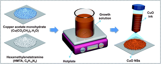
Caterpillar-like CuO NSs were synthesized using a simple, green, low-temperature and wet-chemical approach (Scheme 1). In a typical synthesis, 10 mM Cu(CO2CH3)2·H2O was dissolved in a glass beaker containing 900 ml of DI water at room temperature (RT). The beaker was then covered with a polyethylene cap and the solution was slowly heated to 80 °C using a hotplate. After the copper salt solution had reached 80 °C, twice the amount of HMTA (20 mM) was slowly added under constant magnetic stirring. As HMTA was added to the copper salt solution, the growth solution color gradually changed from blue to brownish. The total reaction time to induce nucleation and growth was about 30 min, and the solution was allowed to cool down to RT naturally. Ultimately, the supernatant liquid was separated from the beaker after 1 h and the turbid brownish color solution that contained the CuO sample was collected into a centrifuge tube for the drop-casting process. Meanwhile, commercially available and well-cleaned 0.5 × 2.5 cm2 CWTs were prepared and placed on the hotplate at 140 °C. Next, the CuO solution was drop-casted on CWTs (active material area of 0.5 × 2 cm2) and dried completely to remove moisture. As a result, the CuO NSs strongly adhered to the surface of the CWTs. The mass loading of the caterpillar-like CuO NSs on CWTs was about 1.0 ± 0.02 mg cm−2. To investigate the physicochemical properties of the as-prepared CuO, the powder sample was filtered, washed with ethanol and DI water, and followed by drying at 60 °C for 6 h.Characterization
Morphological properties of the caterpillar-like CuO NSs were investigated by using a field-emission scanning electron microscope (FE-SEM, Carl Zeiss, LEOSUPRA 55, Reutlingen, Germany) and transmission electron microscope (TEM, JEM 200CX, JEOL, Tokyo, Japan) equipped with energy-dispersive, X-ray spectroscopy (EDX). Crystallinity of the prepared material was verified on a Mac Science (M18XHF-SRA) X-ray powder diffractometer with Cu Kα radiation (λ = 1.54178 Å). The Raman analysis was carried out by using a high-resolution Raman spectrophotometer (HR-Raman Spectrometer, inVia) from 700 to 200 cm−1 at RT. Chemical compositions and oxidation states of the prepared sample were analyzed by X-ray photoelectron spectroscopy (XPS; Thermo Multi-Lab 2000 System). The surface area and pore size diameter of the sample were evaluated by BET analysis (BELSORP-max (MP)).Electrochemical measurements
Electrochemical measurements were carried out in a three-electrode-cell system with an Ag/AgCl reference electrode, a Pt wire as counter electrode and the caterpillar-like CuO NSs-painted CWTs as a working electrode in the pristine KOH electrolyte (1 M) and redox-additive electrolyte (1 M KOH + 0.01 M K3Fe(CN)6) solutions at RT. All electrochemical properties including cyclic voltammetry (CV), galvanic charge–discharge (GCD) and electrochemical impedance spectroscopy (EIS) analyses were performed with an IviumStat electrochemical workstation (Ivium Technologies, The Netherlands). For practical applications, the full cell was assembled using the caterpillar-like CuO NSs-adhered CWTs as a positive electrode and the activated carbon coated on carbon fabric (AC on CF) as a negative electrode, with a piece of cellulose paper as a separator in the redox-additive electrolyte. The detailed process for the preparation of AC on CF is included in the (ESI,† Section 1). Areal capacitance (Cac, mF cm−2) of the active material-coated electrodes is calculated using the following formula:12,49 | (1) |
Results and discussion
XRD analysis was first performed to study the crystalline phase and structure of the prepared CuO NSs, as shown in Fig. 1(a) and (b). CuO exhibited obvious diffractions at two theta (2θ) degrees of 32.51, 35.55, 38.72, 48.75, 53.40, 58.31, 61.56, 66.22, 68.13, 72.41, and 75.22°, corresponding to the crystal planes of (110), (![[1 with combining macron]](https://www.rsc.org/images/entities/char_0031_0304.gif) 11), (111), (
11), (111), (![[2 with combining macron]](https://www.rsc.org/images/entities/char_0032_0304.gif) 02), (020), (202), (
02), (020), (202), (![[1 with combining macron]](https://www.rsc.org/images/entities/char_0031_0304.gif) 13), (
13), (![[3 with combining macron]](https://www.rsc.org/images/entities/char_0033_0304.gif) 11), (220), (311), and (
11), (220), (311), and (![[2 with combining macron]](https://www.rsc.org/images/entities/char_0032_0304.gif) 22), respectively, as seen in Fig. 1(a). All these peaks were perfectly indexed to the pure monoclinic CuO phase (JCPDS card no. 05-0661) without impurities.50 The XRD pattern was also well fitted by the Rietveld refinement analysis with space group C2/c (15), as shown in Fig. 1(b). Rietveld refinement results for the CuO NSs are presented in Table S1.† Unit cell parameters obtained are as follows: a = 4.685 Å, b = 3.417 Å, c = 5.141 Å and V = 81.187 Å. The crystal structure of thermodynamically stable CuO was drawn using Diamond software (see the inset of Fig. 1(a)). Atomic coordinates and structural parameters obtained from the refinement (Table S1†) were used to draw the crystal structure. The CuO crystal structure is formed by crossing bonds of CuO4, as shown in Fig. 1(a). The refined crystal structure shows the rectangular parallelogram around Cu atom formed by four coplanar O atoms, and a polyhedron around the O atom formed by four Cu atoms at the corners of a distorted tetrahedron.
22), respectively, as seen in Fig. 1(a). All these peaks were perfectly indexed to the pure monoclinic CuO phase (JCPDS card no. 05-0661) without impurities.50 The XRD pattern was also well fitted by the Rietveld refinement analysis with space group C2/c (15), as shown in Fig. 1(b). Rietveld refinement results for the CuO NSs are presented in Table S1.† Unit cell parameters obtained are as follows: a = 4.685 Å, b = 3.417 Å, c = 5.141 Å and V = 81.187 Å. The crystal structure of thermodynamically stable CuO was drawn using Diamond software (see the inset of Fig. 1(a)). Atomic coordinates and structural parameters obtained from the refinement (Table S1†) were used to draw the crystal structure. The CuO crystal structure is formed by crossing bonds of CuO4, as shown in Fig. 1(a). The refined crystal structure shows the rectangular parallelogram around Cu atom formed by four coplanar O atoms, and a polyhedron around the O atom formed by four Cu atoms at the corners of a distorted tetrahedron.
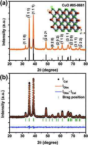 | ||
| Fig. 1 (a) XRD pattern and (b) Rietveld refinement for synthesized caterpillar-like CuO NSs. Inset in (a) shows crystal structure of CuO. | ||
Detailed morphological properties of the as-prepared CuO were investigated by TEM analysis, shown in Fig. 2. To prepare the sample for TEM, a small quantity of CuO powder was dispersed in ethanol by sonication for 10 min. The ethanolic solution containing CuO was then dropped onto the TEM grid and dried in air for a few minutes before loading into the TEM chamber. As displayed in the low-magnification TEM image of Fig. 2(a), the CuO NSs exhibited ellipsoidal body-shaped architectures with a size of ∼80–100 nm and 140–160 nm in width and length, respectively. Each of these CuO NSs was bounded by several nanohairs and appeared like 3D nanoarchitectures, as shown in Fig. 2(b). The appearance of these NSs was similar to a natural caterpillar (inset of Fig. 2(a)). Also, the appearance of white spots in the magnified TEM image (Fig. 2(b)) of the caterpillar-like CuO NSs demonstrates porosity. Such porous nature of the electroactive material is favorable for efficient electrochemical reactions with an electrolyte solution to improve energy storage performance. From the high-resolution TEM (HR-TEM) image (marked with a yellow circle), the lattice fringe width spacing of 0.23 nm corresponds to the (111) crystal plane of CuO, as shown in Fig. 2(c). In fact, this (111) plane was found to be the most intense peak in the XRD spectrum as well. As seen in the selected area electron diffraction (SAED) pattern, several ring-pattern spots are well indexed to the monoclinic CuO phase. Meanwhile, the EDX spectrum (Fig. 2(e)) and its corresponding elemental mapping images of the prepared sample (Fig. 2(f) and (g)) indicate that the caterpillar-like CuO NSs were mainly composed of Cu (red) and O (green) elements without impurities.
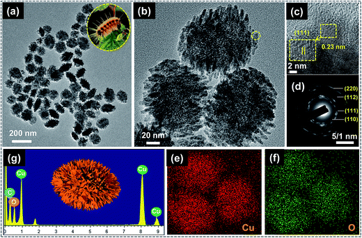 | ||
| Fig. 2 (a and b) TEM images of caterpillar-like CuO NSs. (c and d) HR-TEM image and SAED pattern of magnified part in (c). (g–f) EDX pattern and elemental mapping images of the corresponding sample. | ||
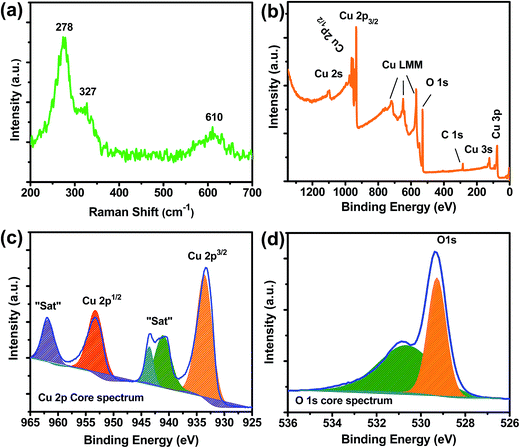
The typical Raman spectrum of caterpillar-like CuO is also presented in Fig. 3(a) to confirm its formation. An examination of this spectrum clearly shows the three well-known peaks, related to the pure CuO, and this is similar to the earlier reports on CuO-based nanomaterials. The three Raman peaks were observed at 278 cm−1 corresponding to the Ag band and at 327 and 610 cm−1 related to the 2Bg bands. XPS analysis was also performed to further investigate the surface oxidation states and elemental compositions of Cu and O elements in the caterpillar-like CuO NSs (Fig. 3(b–d)). A complete view of the surface elemental compositions of the caterpillar-like CuO NSs shown in the survey scan spectrum of Fig. 3(b) clearly demonstrates that the material is composed of Cu and O elements only; no impurities were found on the CuO surface. The C 1s peak at around 284.6 eV was used as a reference to monitor binding energies of the sample. As seen in the high-resolution survey scan spectrum of Cu 2p (Fig. 3(c)), two major peaks located at 933.6 and 953.2 eV, with two adjacent shakeup satellite peaks, were related to the Cu 2p3/2 and Cu 2p1/2 core levels. The presence of these spin–orbit doublets at the corresponding binding energy values clearly indicates that the oxidation state of Cu species in CuO is +2. Meanwhile, the core-level spectrum of O 1s displays that the spectrum can be resolved into two peaks. As shown in Fig. 3(d), the observed peaks at the binding energy value of 529.3 eV are related to the lattice oxygen and another peak located at 531.6 eV corresponds to the oxygen absorbed on the sample surface.51 These results further confirmed that the synthesized sample was of high purity. Fig. S2† represents the N2 adsorption–desorption isotherms and the pore size distribution curves of the caterpillar-like CuO NSs. Herein, the specific surface area of the CuO NSs was measured using the BET (Brunauer–Emmett–Teller) method and the pore size diameter was measured from the pore volume distribution curve (inset of Fig. S2†) using the BJH (Barrett–Joyner–Halenda) method. From Fig. S2,† it is evident that the caterpillar-like CuO NSs show a typical type IV isotherm of the IUPAC classification hysteresis loop, indicating a mesoporous nature of the prepared material. The resulting BET surface area for the caterpillar-like CuO NSs was about 70.3 m2 g−1. Moreover, the average pore diameter and total pore volume on the basis of BJH curve were found to be 8.4 nm and 0.15 cm3 g−1, respectively. Such proper pore size will ensure penetrable mesochannels for the passage of electrolyte ions, resulting in increased ion diffusion kinetics. Meanwhile, the higher surface area and pore volume will also play a key role in providing shorter paths for ion diffusion, leading to more electroactive sites for rapid electrochemical reactions.39
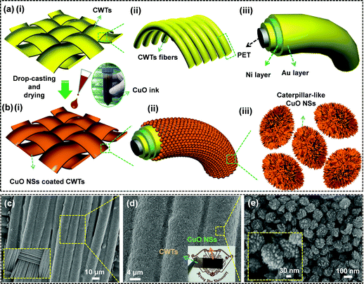
The fabrication process for caterpillar-like CuO NSs on CWTs by a facile and green drop-casting approach is schematically illustrated in Fig. 4. The CWTs used in this work consisted of orderly weaved conductive fibers and each fiber was layered with highly conductive gold (Au) and nickel (Ni) films on polyethylene terephthalate (PET) fiber, as shown in Fig. 4(a)(i–iii). The multi-layering of Au and Ni on PET fibers offers lower resistance (0.03–0.05 Ω sq.−1) to the CWTs. Such a highly conductive feature of the CWTs is useful for the current collector in a supercapacitor, to rapidly transport electrons. In addition, the CWTs not only showed lower resistance but also exhibited a relatively high flexibility and foldability (see photographs in Fig. S1†). After cleaning with ethanol and DI water, the CWTs were dried with nitrogen gas. Well-cleaned 0.5 × 2.5 cm2 CWTs were placed on the 140 °C hotplate. Next, a homogeneously distributed turbid CuO solution in a centrifuge tube (i.e., the brownish-black colored precipitate obtained after decanting the supernatant from a sedimented solution in a growth beaker) was dropped with a pipette onto the surfaces of the CWTs via the drop-casting method, as shown in Fig. 4(b)(i–iii). The dropped solution was allowed to dry for 15 min to completely remove the moisture. The weight of sample mass on the CWTs before and after coating with CuO was about 1.0 ± 0.02 mg cm−2. The surface morphology and the adhesion property of the CuO NSs on CWTs were characterized by FE-SEM observations. As shown in the low-magnification FE-SEM image in Fig. 4(c), the sample was uniformly coated on the entire surface of CWTs without cracks or gaps. Increased magnification clearly shows in Fig. 4(d) that CWTs fibers were abundantly covered with CuO, even in interstitial areas with strong adhesion. The inset of Fig. 4(d) displays the photographic image of the CuO NSs-painted CWTs. From the high-magnification FE-SEM image in Fig. 4(e), the caterpillar-like CuO NSs were densely gathered together and several inner pores were observed, which is helpful for accelerating ion transfer between the electrolyte and active materials.
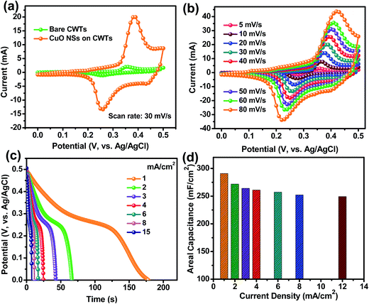
The electrochemical behavior of the caterpillar-like CuO NSs-painted CWTs was investigated in a three-electrode cell system using 1 M KOH as the electrolyte at RT. Fig. 5(a) shows the comparative CV curves of the pristine CWTs and caterpillar-like CuO NSs coated on CWTs electrodes at a constant scan rate of 30 mV s−1 in the potential range of 0–0.5 V. Based on the CV curves, bare CWTs in 1 M KOH electrolyte displayed the lowest current response, indicating that they contribute little to total capacitance. Meanwhile, the CuO NSs on the CWTs electrode exhibited a couple of strong redox peaks due to reversible reactions between Cu2+ to Cu+ and Cu+ to Cu2+ in electrolyte solution, demonstrating the pseudocapacitive behavior of the electroactive material. Moreover, the CV profiles of the CuO NSs on CWTs electrode under different scan rates (ranging 5–80 mV s−1) revealed increased peak current values with increasing scan rates (Fig. 5(b)). CV curve shapes were well defined even under higher scan rates, indicating a quick response to the fast potential sweep and good electrochemical reversibility of CuO NSs.
In order to study the energy storage ability of the caterpillar-like CuO, GCD analysis was performed at different applied current densities. As shown in Fig. 5(c), the discharge profile appearance does not match ideal straight lines, which further confirms the pseudocapacitive redox behavior of the CuO NSs in aqueous electrolyte solution. The small voltage drop at high current densities during the discharge process is attributed to CuO internal resistance. The calculated Cac values as a function of applied current density from the discharge curves are plotted in Fig. 5(d). At the current densities of 1, 2, 3, 4, 6, 8 and 12 mA cm−2, the caterpillar-like CuO NSs on CWTs showed maximum Cac values of 290.87, 271.7, 264.06, 260.82, 257.17, 252.1 and 249.2 mF cm−2, respectively, indicating excellent rate capability of the material. The excellent energy storage properties of the caterpillar-like CuO NSs on CWTs are mainly attributed to the hierarchical structure with high surface area which provides an easy pathway for diffusion of electrolyte ions for efficient redox reactions.
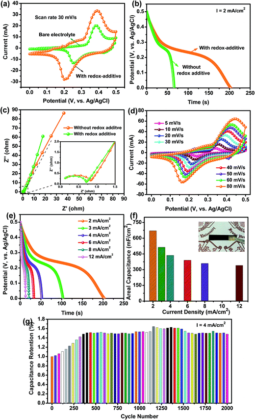
The electrochemical performance of the caterpillar-like CuO NSs on CWTs was further increased by adding appropriate amounts of redox-additive K3Fe(CN)6 (0.01 M) into the aqueous 1 M KOH electrolyte solution. Comparative CV curves of the caterpillar-like CuO NSs on the CWTs electrode in the three-electrode system with and without redox-additive electrolyte are shown in Fig. 6(a). Clearly, the CV curves measured in the presence of redox electrolyte show a larger enclosed CV area than for the bare 1 M KOH electrolyte (i.e., without redox additive), which is indicative of superior electrochemical properties of the electrode in the redox-additive electrolyte.
Galvanic discharge profiles measured at a current density of 2 mA cm−2 are shown in Fig. 6(b). A significantly higher discharge time was observed for the redox-additive electrolyte used with CuO NSs on the CWTs electrode than for the bare 1 M KOH. From the discharge time of CuO NSs on the CWTs electrode, the calculated Cac value was approximately 670.68 mF cm−2 in redox-additive electrolyte, which is about 2.46 times higher than for the bare 1 M KOH electrolyte. The increased Cac of CuO NSs in the redox electrolyte could be ascribed to enhanced redox reactions of Fe(CN)63− and Fe(CN)64−, where both redox couples act as an “electron shuttle” in the charge–discharge process.29,46 As a result of the quick reversible reactions, enhanced energy storage abilities were obtained for the CuO NSs on CWTs electrode in the redox-additive electrolyte. In addition, EIS analysis was conducted to examine the conductivity of electrode materials and to explore the importance of K3Fe(CN)6 in aqueous 1 M KOH electrolyte solution for improved capacitance (Fig. 6(c)). Nyquist plots of the caterpillar-like CuO NSs on CWTs were measured in the frequency range of 0.01 Hz to 100 kHz at the open circuit potential in both electrolytes. Common characteristics of a semicircle at high frequencies and an inclined line at low frequencies were observed in the EIS curves. In the case of redox-additive electrolyte, the charge transfer resistance (Rct) of the CuO NSs on the CWTs electrode exhibited a lower value than for the bare KOH electrolyte. Furthermore, the CV curves of the CuO NSs on the CWTs electrode under various scan rates were measured to examine the electrochemical reversibility mechanism in redox-additive electrolyte. In Fig. 6(d), the CV profiles of the CuO NSs on the CWTs electrode in redox-additive electrolyte show a similar pseudocapacitive behavior, with larger peak current values on increasing the scan rate. At increased scan rates, the redox potentials also shifted within the applied potential sweep and maintained similar CV shapes, which confirms that the ionic and electronic transport of the electrode is rapid enough in the redox-additive electrolyte for the applied scan rates. The superior energy storage performance of the electrode in redox-additive electrolyte was ultimately demonstrated by galvanostatic discharge analysis. Discharge curves measured at different current densities are shown in Fig. 6(e) and the calculated Cac values as a function of discharge current density are plotted in Fig. 6(f). The maximum Cac value of 670.68 mF cm−2 was obtained at a current density of 2 mA cm−2; even at a high discharge current density of 12 mA cm−2, the redox electrolyte material showed a Cac value of 339.9 mA cm−2, with a capacitance retention of 50.67%. The decreased capacitance under enhanced current densities may be due to the redox reactions moving gradually to keep pace with higher current densities. Such enhanced energy storage performance of the caterpillar-like CuO NSs on CWTs was higher than previous reports of the similar CuO or its nanocomposites (Table S2†). The cyclic stability of the caterpillar-like CuO NSs on CWTs was investigated up to 2000 cycles at a current density of 4 mA cm−2 in redox-additive electrolyte, as shown in Fig. 6(g). Interestingly, the Cac was gradually increased during the initial 400 cycles and afterwards the Cac was stable with little fluctuation. Capacitance retention after 2000 cycles was observed at about 1.48%. Increased Cac during the initial cycles was mainly attributed to the activation process of the caterpillar-like CuO NSs by rapid diffusion of electrolyte ions, which is similar to previous reports.30,52 The photograph of the working electrode after 2000 cycles shown in the inset of Fig. 6(f) clearly demonstrates that the active material (i.e., caterpillar-like CuO NSs) still adhered to the CWTs without any mass loss.
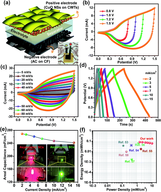
The enhanced electrochemical properties of the devices in view of both high power density and energy density are crucial for practical SC applications. To examine the possible energy storage performance of the caterpillar-like CuO NSs on CWTs, we assembled asymmetric SCs using caterpillar-like CuO NSs on CWTs as the positive electrode and AC on CF as the negative electrode. Fig. 7(a) shows the schematic and photograph of the fabricated device with a few ml of redox-additive electrolyte. Before assembling the device, the electrochemical behavior of the AC on CF was investigated (see Fig. S3†) to balance the mass on each electrode to obtain consistent energy storage performance. According to the mass balancing relationship as shown in eqn (2), mass on both electrodes was optimized:29
 | (2) |
Most two-electrode systems that employed asymmetric SCs could not accomplish higher Cac as did the three-electrode systems. This is because the Cac value of the asymmetric SCs was strongly affected by the mass of electroactive materials on both electrodes and by cell configuration. In addition, the Cac value was further dependent on the overall potentials of both electrodes. Therefore, achieving higher Cac values was somewhat difficult. The cycling stability of this asymmetric SC was also tested up to 2000 cycles at a current density of 7 mA cm−2, as shown in Fig. S5.† Without capacitance loss, the device still exhibited capacitance retention of 1.3% with the initial cycle after 2000 cycles, indicating superior cycling stability. This enhanced capacitance during GCD cycles is ascribed to the activation process of both electrodes. The amount of energy stored and delivered by the as-fabricated asymmetric SCs is also crucial for practical applications. Fig. 7(f) shows the comparative Ragone plot of the fabricated asymmetric SCs with some of the recently reported devices. Herein, the energy density (Ed, mW h cm−2) and power density (Pd, mW cm−2) values were calculated using the following formulas:52
 | (3) |
 | (4) |
Conclusions
A facile, green, single-step and wet-chemical approach was used to synthesize hierarchical CuO NSs with caterpillar-like morphologies. Next, the CuO NSs were uniformly painted on flexible CWTs using a drop-casting method and used as a binder-free electrode in SCs. The electrochemical performance of the CuO NSs coated on CWTs revealed a Cac value of 271.7 mF cm−2 at 2 mA cm−2 in 1 M KOH solution, which was then further enhanced to 670.68 mF cm−2 under the same current density by introducing a small portion of redox-additive K3Fe(CN)6 to aqueous 1 M KOH electrolyte solution. The enhanced Cac of CuO NSs on CWTs was mainly attributed to rapid redox reactions of the CuO and Fe(CN)63−/Fe(CN)64− redox couple, which accelerates the electron transfer for improved energy storage performance. Furthermore, asymmetric SCs were assembled, exhibiting a maximum Ed value of 0.082 mW h cm−2 and a Pd of 10.1 mW cm−2, which could illuminate commercial LEDs. The unique structure of metal-oxide NSs, flexible conductive textiles and redox-additive electrolytes to improve the energy storage abilities provides a deep insight and understanding for high-performance SC applications.Acknowledgements
This work was supported by the National Research Foundation of Korea (NRF) grant funded by the Korean government (MSIP) (2013R1A2A2A01068407).References
- L. Hu and Y. Cui, Energy Environ. Sci., 2012, 5, 6423–6435 Search PubMed.
- S. Choi, H. Lee, R. Ghaffari, T. Hyeon and D.-H. Kim, Adv. Mater., 2016, 28, 4203–4218 CrossRef CAS PubMed.
- K. Jost, G. Dion and Y. Gogotsi, J. Mater. Chem. A, 2014, 2, 10776–10787 CAS.
- S. Wang, B. Pei, X. Zhao and R. A. W. Dryfe, Nano Energy, 2013, 2, 530–536 CrossRef CAS.
- J. Liu, L. Zhang, H. B. Wu, J. Lin, Z. Shen and X. W. Lou, Energy Environ. Sci., 2014, 7, 3709–3719 CAS.
- T. G. Yun, M. Oh, L. Hu, S. Hyun and S. M. Han, J. Power Sources, 2013, 244, 783–791 CrossRef CAS.
- P. Yang, Y. Chen, X. Yu, P. Qiang, K. Wang, X. Cai, S. Tan, P. Liu, J. Song and W. Mai, Nano Energy, 2014, 10, 108–116 CrossRef CAS.
- H. Nishide and K. Oyaizu, Science, 2008, 319, 737–738 CrossRef CAS PubMed.
- Y. Hou, L. Chen, P. Liu, J. Kang, T. Fujita and M. Chen, J. Mater. Chem. A, 2014, 2, 10910–10916 CAS.
- X. Cai, M. Peng, X. Yu, Y. Fu and D. Zou, J. Mater. Chem. C, 2014, 2, 1184–1200 RSC.
- X. Wang, X. Lu, B. Liu, D. Chen, Y. Tong and G. Shen, Adv. Mater., 2014, 26, 4763–4782 CrossRef CAS PubMed.
- G. Nagaraju, R. Kakarla, S. M. Cha and J. S. Yu, Nano Res., 2015, 8, 3749–3763 CrossRef CAS.
- W. Zuo, C. Wang, Y. Li and J. Liu, Sci. Rep., 2015, 5, 7780 CrossRef CAS PubMed.
- Z. Ma, X. Huang, S. Dou, J. Wu and S. Wang, J. Phys. Chem. C, 2014, 118, 17231–17239 CAS.
- P. Simon and Y. Gogotsi, Nat. Mater., 2008, 7, 845–854 CrossRef CAS PubMed.
- G. Nagaraju, G. S. R. Raju, Y. H. Ko and J. S. Yu, Nanoscale, 2016, 8, 812–825 RSC.
- J. Liu, J. Sun and L. Gao, J. Phys. Chem. C, 2010, 114, 19614–19620 CAS.
- L.-F. Chen, Z.-Y. Yu, X. Ma, Z.-Y. Li and S.-H. Yu, Nano Energy, 2014, 9, 345–354 CrossRef CAS.
- X. Zhou, Q. Chen, A. Wang, J. Xu, S. Wu and J. Shen, ACS Appl. Mater. Interfaces, 2016, 8, 3776–3783 CAS.
- Y.-K. Hsu, Y.-C. Chen, Y.-G. Lin, L.-C. Chen and K.-H. Chen, J. Mater. Chem., 2012, 22, 3383–3387 RSC.
- F. Wang, S. Xiao, Y. Hou, C. Hu, L. Liu and Y. Wu, RSC Adv., 2013, 3, 13059–13084 RSC.
- X. Lu, M. Yu, G. Wang, Y. Tong and Y. Li, Energy Environ. Sci., 2014, 7, 2160–2181 Search PubMed.
- R. Li, Y. Wang, C. Zhou, C. Wang, X. Ba, Y. Li, X. Huang and J. Liu, Adv. Funct. Mater., 2015, 25, 5384–5394 CrossRef CAS.
- L. L. Zhang and X. S. Zhao, Chem. Soc. Rev., 2009, 38, 2520–2531 RSC.
- M. Yu, W. Qiu, F. Wang, T. Zhai, P. Fang, X. Lu and Y. Tong, J. Mater. Chem. A, 2015, 3, 15792–15823 CAS.
- A. Mahmood, R. Zou, Q. Wang, W. Xia, H. Tabassum, B. Qiu and R. Zhao, ACS Appl. Mater. Interfaces, 2016, 8, 2148–2157 CAS.
- G. K. Veerasubramani, K. Krishnamoorthy and S. J. Kim, RSC Adv., 2015, 5, 16319–16327 RSC.
- C.-C. Hu, K.-H. Chang, M.-C. Lin and Y.-T. Wu, Nano Lett., 2006, 6, 2690–2695 CrossRef CAS PubMed.
- G. K. Veerasubramani, K. Krishnamoorthy and S. J. Kim, J. Power Sources, 2016, 306, 378–386 CrossRef CAS.
- G. Nagaraju, Y. H. Ko, S. M. Cha, S. H. Im and J. S. Yu, Nano Res., 2016, 9, 1507–1522 CrossRef CAS.
- G. Wang, J. Huang, S. Chen, Y. Gao and D. Cao, J. Power Sources, 2011, 196, 5756–5760 CrossRef CAS.
- Y.-S. Kim, I.-S. Hwang, S.-J. Kim, C.-Y. Lee and J.-H. Lee, Sens. Actuators, B, 2008, 135, 298–303 CrossRef CAS.
- Y. H. Ko, G. Nagaraju, S. H. Lee and J. S. Yu, Mater. Lett., 2014, 117, 217–220 CrossRef CAS.
- A. Bhaumik, A. Haque, P. Karnati, M. F. N. Taufique, R. Patel and K. Ghosh, Thin Solid Films, 2014, 572, 126–133 CrossRef CAS.
- G. Nagaraju, Y. Hwan Ko and J. Su Yu, Mater. Lett., 2014, 116, 64–67 CrossRef CAS.
- V. Senthilkumar, Y. S. Kim, S. Chandrasekaran, B. Rajagopalan, E. J. Kim and J. S. Chung, RSC Adv., 2015, 5, 20545–20553 RSC.
- B. Vidyadharan, R. A. Aziz, I. I. Misnon, G. M. Anil Kumar, J. Ismail, M. M. Yusoff and R. Jose, J. Power Sources, 2014, 270, 526–535 CrossRef CAS.
- J. Zhang, H. Feng, Q. Qin, G. Zhang, Y. Cui, Z. Chai and W. Zheng, J. Mater. Chem. A, 2016, 4, 6357–6367 CAS.
- S. E. Moosavifard, M. F. El-Kady, M. S. Rahmanifar, R. B. Kaner and M. F. Mousavi, ACS Appl. Mater. Interfaces, 2015, 7, 4851–4860 CAS.
- Y. Lu, H. Yan, K. Qiu, J. Cheng, W. Wang, X. Liu, C. Tang, J.-K. Kim and Y. Luo, RSC Adv., 2015, 5, 10773–10781 RSC.
- P. Xu, K. Ye, M. Du, J. Liu, K. Cheng, J. Yin, G. Wang and D. Cao, RSC Adv., 2015, 5, 36656–36664 RSC.
- P. Xu, J. Liu, T. Liu, K. Ye, K. Cheng, J. Yin, D. Cao, G. Wang and Q. Li, RSC Adv., 2016, 6, 28270–28278 RSC.
- A. Vlad, N. Singh, J. Rolland, S. Melinte, P. M. Ajayan and J. F. Gohy, Sci. Rep., 2014, 4, 4315 CrossRef CAS PubMed.
- S. T. Senthilkumar, R. K. Selvan and J. S. Melo, J. Mater. Chem. A, 2013, 1, 12386–12394 CAS.
- L. Qian, X. Tian, L. Yang, J. Mao, H. Yuan and D. Xiao, RSC Adv., 2013, 3, 1703–1708 RSC.
- L.-H. Su, X.-G. Zhang, C.-H. Mi, B. Gao and Y. Liu, Phys. Chem. Chem. Phys., 2009, 11, 2195–2202 RSC.
- A. Singh and A. Chandra, Sci. Rep., 2016, 6, 25793 CrossRef CAS PubMed.
- J. Wu, H. Yu, L. Fan, G. Luo, J. Lin and M. Huang, J. Mater. Chem., 2012, 22, 19025–19030 RSC.
- X.-F. Lu, Z.-X. Huang, Y.-X. Tong and G.-R. Li, Chem. Sci., 2016, 7, 510–517 RSC.
- X. Fei, Z. Shao and X. Chen, Nanoscale, 2013, 5, 7991–7997 RSC.
- C. Dong, X. Xing, N. Chen, X. Liu and Y. Wang, Sens. Actuators, B, 2016, 230, 1–8 CrossRef CAS.
- G. Nagaraju, S. M. Cha, S. C. Sekhar and J. S. Yu, Adv. Energy Mater. DOI:10.1002/aenm.201601362.
- K. K. Purushothaman, B. Saravanakumar, I. M. Babu, B. Sethuraman and G. Muralidharan, RSC Adv., 2014, 4, 23485–23491 RSC.
- M. Huang, Y. Zhang, F. Li, Z. Wang, Alamusi, N. Hu, Z. Wen and Q. Liu, Sci. Rep., 2014, 4, 4518 Search PubMed.
- T. Zhai, S. Xie, M. Yu, P. Fang, C. Liang, X. Lu and Y. Tong, Nano Energy, 2014, 8, 255–263 CrossRef CAS.
- S. T. Senthilkumar, R. K. Selvan, M. Ulaganathan and J. S. Melo, Electrochim. Acta, 2014, 115, 518–524 CrossRef CAS.
- J. Ren, W. Bai, G. Guan, Y. Zhang and H. Peng, Adv. Mater., 2013, 25, 5965–5970 CrossRef CAS PubMed.
- V. T. Le, H. Kim, A. Ghosh, J. Kim, J. Chang, Q. A. Vu, D. T. Pham, J.-H. Lee, S.-W. Kim and Y. H. Lee, ACS Nano, 2013, 7, 5940–5947 CrossRef CAS PubMed.
Footnote |
| † Electronic supplementary information (ESI) available. See DOI: 10.1039/c6ta10428b |
| This journal is © The Royal Society of Chemistry 2017 |

