 Open Access Article
Creative Commons Attribution 3.0 Unported Licence
An interfacial engineering approach towards two-dimensional porous carbon hybrids for high performance energy storage and conversion†
Chenbao
Lu
ab,
Shaohua
Liu
 b,
Fan
Zhang
*b,
Yuezeng
Su
*a,
Xiaoxin
Zou
c,
Zhan
Shi
c,
Guodong
Li
c and
Xiaodong
Zhuang
*bd
aSchool of Chemistry and Chemical Engineering, State Key Laboratory of Metal Matrix Composites, 200240 Shanghai, P. R. China. E-mail: yzsu@sjtu.edu.cn
bShanghai Key Lab of Electrical Insulation and Thermal Ageing, Shanghai Electrochemical Energy Devices Research Center, School of Chemistry and Chemical Engineering, Shanghai Jiao Tong University, 200240 Shanghai, P. R. China. E-mail: fan-zhang@sjtu.edu.cn; zhuang@sjtu.edu.cn
cState Key Laboratory of Inorganic Synthesis and Preparative Chemistry, International Joint Research Laboratory of Nano–Micro Architecture Chemistry, College of Chemistry, Jilin University, Changchun 130012, P. R. China
dCenter for Advancing Electronics Dresden (cfaed), Department of Chemistry and Food Chemistry, Technische Universität Dresden, Mommsenstrasse 4, Dresden 01062, Germany
First published on 5th December 2016
Abstract
In order to improve the performance and fundamental understanding of conducting polymers, development of new nanotechnologies for engineering aggregated states and morphologies is one of the central focuses for conducting polymers. In this work, we demonstrated an interfacial engineering method for the rational synthesis of a two-dimensional (2D) polyaniline (PANI) nano-array and its corresponding nitrogen-doped porous carbon nanosheets. Not only was it easy to produce a sandwich-like 2D morphology, but also the thickness, anchored ions and produced various metal phosphides were easily and rationally engineered by controlling the composition of the aqueous layer. The novel structural features of these hybrids enabled outstanding electrochemical capacitor performance. The specific capacitance of the as-produced diiron phosphide embedded nitrogen-doped porous carbon nanosheets was calculated to be as high as 1098 F g−1 at 1 A g−1 and an extremely high specific capacitance of 611 F g−1 at 10 A g−1, outperforming state-of-the-art performance among porous carbon and metal-phosphide-based supercapacitors. We believe that this interfacial approach can be extended to the controllable synthesis of various 2D material coupled sandwich-like hybrid materials with potential applications in a wide range of areas.
Introduction
Since the discovery of conducting polymers, polyaniline (PANI) has captured the attention of the scientific community because of its unique chemical structure, optoelectronic properties and wide applications.1 Given that the nano-architecture of materials plays a crucial role in achieving the promising fundamental properties. Over the past decade, a lot of synthetic strategies toward PANIs with different doping states2 and various nanostructures, such as nanospheres,3 nanofibers,4 nanotubes,5 and nanosheets,6 have been extensively developed due to the urgent requirements in optoelectronic and energy related fields.2,7 However, most of the methods for nanostructured PANI production can only be carried out in homogeneous solution with the aid of vigorous stirring, heating or high pressure, suffering from complicated procedures and a difficult-to-control morphology.7 It has long been noticed that the interfacial method can be used to prepare PANI and its composites.2,8 However, synthesis of conducting polymers with a controllable aggregation state and morphology through an interfacial approach still remains great challenge.Two-dimensional (2D) nanomaterials have attracted tremendous attention since the discovery of graphene. Of these, 2D soft nanomaterials,9 such as graphene-coupled conducting polymer nanosheets, 2D sandwich-like conjugated microporous polymers and other types of 2D materials, have been studied and used as crucial materials for many optoelectronic and energy applications in the past few years,10 for example, as porous materials for sensing, gas storage and separation, and as precursors for the preparation of 2D hybrid materials for energy storage and conversion. Considerable efforts have been made to prepare graphene-based 2D hybrid materials such as composites of graphene-based transition metals, metal oxides, metal chalcogenides, and metal phosphides (MPs).11 Besides, both metal supported and free-standing chemical vapor deposition (CVD) graphene have been used as templates to fish nanoparticles from organic/aqueous interfaces to prepare asymmetric MoS2/graphene/metal sandwiches and noble metal particles loaded graphene, respectively.12 However, due to the general poor compatibility between graphene and substantially dissimilar precursors, the controlled growth of small nanoparticles on graphene surfaces still relies on varied and complicated synthetic procedures.13
Herein, an interfacial approach was successfully developed for the fast preparation of a graphene-coupled polyaniline nano-array with a uniform 2D morphology and in large quantity. Not only can a sandwich-like 2D morphology be easily produced, but the thickness and shape of PANI nano-array, as well as the anchored transition metal cations and acid anions of the as-prepared nanosheets can also be engineered rationally. Consequently, metal phosphide-embedded nitrogen-doped porous carbon nanosheets (denoted as RG@(MP⊂NPC)) can be easily prepared by direct pyrolysis of the as-prepared ion-anchored 2D PANI nano-array. Notably, the as-prepared diiron phosphide-embedded NPC (RG@(Fe2P⊂NPC)), which has an Fe content of only 3.71 wt% and a specific surface area of 240 m2 g−1, exhibits ultrahigh specific capacitances of up to 1098 F g−1 at 1 A g−1 and 611 F g−1 at 10 A g−1, which are more than ten times the values for NPC, Fe2P, and RG@NPC. Thus, it outperforms state-of-the-art supercapacitors based on porous carbons and metal phosphide-based materials. By replacing the metal ions in the aqueous layer, other kinds of MP and dual MP embedded carbon nanosheets can be easily prepared. Such interfacial engineering approach offers a new way for the design and preparation of novel 2D hybrid materials for high performance energy storage and conversion.
Experimental
Chemicals
FeCl3·6H2O, CoCl2·6H2O, Ni(OAc)2·4H2O, (NH4)2Mo4O13·2H2O and aniline were purchased from Aladdin Reagent Co. Ammonium peroxydisulfate (APS), HCl (36 wt%), H3PO4 (80%), H2SO4 (98%), KMnO4, NaNO3, and H2O2 were purchased from Sinopharm Chemical Reagent Co. Pt/C (20 wt%) was purchased from Sigma-Aldrich. Nafion solution (0.5 wt%) was purchased from DuPont, Ltd. All chemicals were used without further purification.Interfacial preparation of GO@PANI
Typically, the interfacial reaction was performed in a 20 mL glass vial. First, ammonium peroxydisulfate (APS, 245 mg, 1 mmol) was dissolved in 8 mL of 1 M dopant acid (HCl) solution. Then, 2 mL of aqueous GO dispersion (2.5 mg mL−1) which was synthesized by a modified Hummers method was slowly added to the acid solution, followed by ultrasonication for 30 min to form a homogeneous suspension, as the aqueous layer. Subsequently, 100 μL aniline was dissolved in the organic phase (10 mL) toluene, as the organic layer. Then, the organic phase was added carefully on top of the aqueous solution, forming an organic/aqueous interface. The steady interface was left to stand for 6 hours at room temperature. The graphene oxide-coupled polyaniline nanosheets (GO@PANI, 1![[thin space (1/6-em)]](https://www.rsc.org/images/entities/char_2009.gif) :
:![[thin space (1/6-em)]](https://www.rsc.org/images/entities/char_2009.gif) 20) was obtained after being centrifuged and washed with DI water and ethanol. The GO@PANI (1
20) was obtained after being centrifuged and washed with DI water and ethanol. The GO@PANI (1![[thin space (1/6-em)]](https://www.rsc.org/images/entities/char_2009.gif) :
:![[thin space (1/6-em)]](https://www.rsc.org/images/entities/char_2009.gif) 10) and GO@PANI (1
10) and GO@PANI (1![[thin space (1/6-em)]](https://www.rsc.org/images/entities/char_2009.gif) :
:![[thin space (1/6-em)]](https://www.rsc.org/images/entities/char_2009.gif) 40) were synthesized by the same procedure with a different weight ratio of GO to aniline.
40) were synthesized by the same procedure with a different weight ratio of GO to aniline.
For the preparation of boric acid (H3BO3) doped PANI nanosheets (GO@(B⊂PANI)), phosphoric acid (H3PO4) doped PANI nanosheets (GO@(P⊂PANI)) and telluric acid (H6TeO6) doped PANI nanosheets (GO@(Te⊂PANI)), the same procedure was employed by just using H3BO3, H3PO4 and H6TeO6 as the doping acids, respectively.
Preparation of metal phosphide anchored N-doped porous carbon nanosheets
Typically, Fe3+ and PO43− anchored PANI nanosheets (GO@(Fe|P⊂PANI)) were first prepared by FeCl3 and H3PO4 involved interfacial polymerization. First, 245 mg APS, 2 mL GO solution, and 1.5 g FeCl3·6H2O were added into 8 mL of 1 M phosphoric acid aqueous solution. Subsequently, 100 μL aniline was dissolved in 10 mL toluene as the organic layer. The organic phase was added carefully on top of the aqueous solution, forming an organic/aqueous interface. After reacting for 6 h, GO@(Fe|P⊂PANI) can be obtained after drying. After thermal treatment of GO@(Fe|P⊂PANI) under a hydrogen/argon (5%) atmosphere at 1000 °C for 2 h, RG@(Fe2P⊂NPC) can be obtained.The synthetic routes of RG@(Co2P⊂NPC), RG@(Ni12P5⊂NPC), and RG@(MoP⊂NPC) are similar to that of RG@(Fe2P⊂NPC) by replacing FeCl3 to the corresponding transition metal salts (CoCl2, Ni(OAc)2 and (NH4)2Mo4O13). For the preparation of Fe2P and Co2P co-anchored NPC nanosheets (RG@(Fe2P|Co2P⊂NPC)), the same procedure was used by adding both FeCl3·6H2O (800 mg) and CoCl2·6H2O (800 mg) into the aqueous solution, as the dopants.
Supercapacitor measurement
The working electrodes were prepared by mixing the as-prepared materials, carbon black (Super-P), and polytetrafluoroethylene (PTFE) at a weight ratio of 80![[thin space (1/6-em)]](https://www.rsc.org/images/entities/char_2009.gif) :
:![[thin space (1/6-em)]](https://www.rsc.org/images/entities/char_2009.gif) 10
10![[thin space (1/6-em)]](https://www.rsc.org/images/entities/char_2009.gif) :
:![[thin space (1/6-em)]](https://www.rsc.org/images/entities/char_2009.gif) 10 and pressed on a platinum net. The area of the active material on each electrode was ∼1.0 cm × 0.5 cm, ∼0.5 mg (RG@(Fe2P⊂NPC): 0.74 mg, RG@NPC: 0.45 mg, NPC: 0.60 mg, Fe2P nanoparticles: 2.46 mg). The electrochemical capacity of materials was evaluated in a three-electrode system, applying 6 M KOH as the electrolyte and platinum wire and a Ag/AgCl (saturated KCl) electrode as the counter and reference electrodes, respectively. The electrochemical performance of samples was determined by cyclic voltammetry (CV) and galvanostatic charge–discharge. All electrochemical experiments were carried out at room temperature.
10 and pressed on a platinum net. The area of the active material on each electrode was ∼1.0 cm × 0.5 cm, ∼0.5 mg (RG@(Fe2P⊂NPC): 0.74 mg, RG@NPC: 0.45 mg, NPC: 0.60 mg, Fe2P nanoparticles: 2.46 mg). The electrochemical capacity of materials was evaluated in a three-electrode system, applying 6 M KOH as the electrolyte and platinum wire and a Ag/AgCl (saturated KCl) electrode as the counter and reference electrodes, respectively. The electrochemical performance of samples was determined by cyclic voltammetry (CV) and galvanostatic charge–discharge. All electrochemical experiments were carried out at room temperature.
Electrochemically catalysed ORR
The electrodes were prepared as follows: 5 mg catalyst was blended with 500 μl Nafion solution (0.05 wt%) and sonication for 2 h, producing catalyst ink. Then 9 μl catalyst ink was pipetted on the surface of a pre-polished glass carbon electrode (0.2471 cm2). The electrodes were dried at room temperature before measurement. The ORR experiments were carried out in a conventional three electrode cell using a Wave Driver 20 bipotentiostatic (Pine Instrument Company, USA) at room temperature. An Ag/AgCl (KCl, 3 M) reference electrode and a platinum wire counter electrode were used in the measurement. All tests were conducted in 0.1 M KOH, and the potentials in this study refer to that of reversible hydrogen electrode (RHE). In 0.1 M KOH, E(RHE) = E(Ag/AgCl) + 0.944 V. CV was performed in the potential range of −0.95–0.05 V vs. Ag/AgCl reference electrode at a sweep rate of 100 mV s−1. RDE and RRDE were measured in O2-saturated 0.1 M KOH at 1600 rpm at a sweep rate of 10 mV s−1.The electron transfer number was determined by the following equation:
| n = 4Id/(Id + Ir/N) | (1) |
The four electron selectivity of the catalysts was evaluated based on the H2O2 yield, calculated from the following equation:
| H2O2 (%) = 200Ir/N(Id + Ir/N) | (2) |
Results and discussion
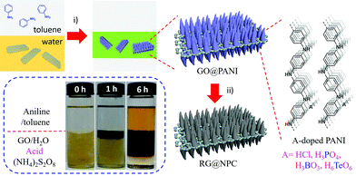
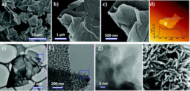
The preparation of GO@PANI through in situ interfacial polymerization is illustrated in Fig. 1. First, GO, oxidant ammonium peroxydisulfate, and dopant acid (HCl) in distilled water were used as the bottom aqueous layer. Aniline in toluene was used as the top organic layer. Subsequently, the organic layer was added carefully on top of the aqueous solution to form a clear organic/aqueous interface (0 h, inset in Fig. 1). Notably, it was found that a dark layer gradually formed at the interface and then thickened considerably. After standing at room temperature for 6–8 hours, the bottom aqueous layer became colorless and transparent, indicating complete consumption of GO. The GO underwent an interfacial synthesis process that can easily be scaled up to produce GO@PANI in batches of up to 0.5 kg for a single preparation (Fig. S1†). At the very beginning, aniline molecules can diffuse through the interface and adsorb on GO surface, which renders the as-produced earliest nanosheets a little bit hydrophobic because the hydrophilic surface of GO would be covered with aniline due the strong electrostatic interaction between amino groups from aniline and hydrophilic groups from GO. The control experiment without GO was also performed (Fig. S2a†); the digital photos of the interfacial polymerization without GO show that the dark green PANI precipitate moves downward due to the increased weight. Moreover, this process enables easy solvent recovery because of the phase separation, rendering it a highly efficient and green approach. After pyrolysis at 1000 °C under a 5% (H2/Ar) atmosphere for 2 h, nitrogen-doped porous carbon nanosheets (RG@NPC) can easily be produced by using GO@PANI as the precursor. The dopant HCl in this approach can easily be replaced with H3PO4, H3BO3, or H6TeO6 to realize different heteroatom (e.g., P, B, and Te) doped porous carbon nanosheets.To understand the interfacial process, the morphology of the as-prepared GO@PANI was imaged using scanning electron microscopy (SEM), transmission electron microscopy (TEM), and atomic force microscopy (AFM). As shown in Fig. 2a–c, numerous free-standing and highly uniform nanosheets were observed. No naked graphene nanosheets or free polyaniline nanofibers (Fig. 2h and S2b–e†) were observed, which suggested that most of the aniline monomers were polymerized on the surface of the graphene. The TEM images (Fig. 2e–g) further revealed an ideal 2D sheet-like morphology as well as uniformly distributed conical PANI arrays for GO@PANI, indicating that the static reaction conditions may have caused favorable orientation of the PANI chains (striped texture14 in Fig. 2g and XRD patterns in Fig. S3†). To reveal the loading capacity of GO, GO@PANI (1![[thin space (1/6-em)]](https://www.rsc.org/images/entities/char_2009.gif) :
:![[thin space (1/6-em)]](https://www.rsc.org/images/entities/char_2009.gif) 10), GO@PANI (1
10), GO@PANI (1![[thin space (1/6-em)]](https://www.rsc.org/images/entities/char_2009.gif) :
:![[thin space (1/6-em)]](https://www.rsc.org/images/entities/char_2009.gif) 20), and GO@PANI (1
20), and GO@PANI (1![[thin space (1/6-em)]](https://www.rsc.org/images/entities/char_2009.gif) :
:![[thin space (1/6-em)]](https://www.rsc.org/images/entities/char_2009.gif) 40) were fabricated using different GO/aniline weight ratios of 1
40) were fabricated using different GO/aniline weight ratios of 1![[thin space (1/6-em)]](https://www.rsc.org/images/entities/char_2009.gif) :
:![[thin space (1/6-em)]](https://www.rsc.org/images/entities/char_2009.gif) 10, 1
10, 1![[thin space (1/6-em)]](https://www.rsc.org/images/entities/char_2009.gif) :
:![[thin space (1/6-em)]](https://www.rsc.org/images/entities/char_2009.gif) 20, and 1
20, and 1![[thin space (1/6-em)]](https://www.rsc.org/images/entities/char_2009.gif) :
:![[thin space (1/6-em)]](https://www.rsc.org/images/entities/char_2009.gif) 40, respectively. As depicted in Fig. S4,† the 2D morphology of GO@PANI can be successfully preserved up to a ratio of 1
40, respectively. As depicted in Fig. S4,† the 2D morphology of GO@PANI can be successfully preserved up to a ratio of 1![[thin space (1/6-em)]](https://www.rsc.org/images/entities/char_2009.gif) :
:![[thin space (1/6-em)]](https://www.rsc.org/images/entities/char_2009.gif) 40. According to AFM analysis (Fig. 2d and S5†), the thicknesses of the GO@PANI (1
40. According to AFM analysis (Fig. 2d and S5†), the thicknesses of the GO@PANI (1![[thin space (1/6-em)]](https://www.rsc.org/images/entities/char_2009.gif) :
:![[thin space (1/6-em)]](https://www.rsc.org/images/entities/char_2009.gif) 10), GO@PANI (1
10), GO@PANI (1![[thin space (1/6-em)]](https://www.rsc.org/images/entities/char_2009.gif) :
:![[thin space (1/6-em)]](https://www.rsc.org/images/entities/char_2009.gif) 20), and GO@PANI (1
20), and GO@PANI (1![[thin space (1/6-em)]](https://www.rsc.org/images/entities/char_2009.gif) :
:![[thin space (1/6-em)]](https://www.rsc.org/images/entities/char_2009.gif) 40) are 12 ± 3, 26 ± 5, and 36 ± 7 nm, respectively. Based on these analysis, such an interfacial assembly process may include three typical steps: (1) aniline molecules diffusing through the toluene/water interface and adsorbing on the GO surfaces, (2) polymerization of aniline on the GO surface in presence of oxidant and diffusing downward due to the increased weight/density, and (3) GO nanosheets and aniline molecules continuously moving upward and downward, respectively, to toluene/water interface due to the concentration gradient and electrostatic interaction between GO and aniline. In such a facile interfacial synthetic approach, not only can the uniform morphologies of the sandwich-like 2D nanosheets be readily obtained, but also the thicknesses can be rationally engineered by only controlling the weight ratio of graphene to aniline.
40) are 12 ± 3, 26 ± 5, and 36 ± 7 nm, respectively. Based on these analysis, such an interfacial assembly process may include three typical steps: (1) aniline molecules diffusing through the toluene/water interface and adsorbing on the GO surfaces, (2) polymerization of aniline on the GO surface in presence of oxidant and diffusing downward due to the increased weight/density, and (3) GO nanosheets and aniline molecules continuously moving upward and downward, respectively, to toluene/water interface due to the concentration gradient and electrostatic interaction between GO and aniline. In such a facile interfacial synthetic approach, not only can the uniform morphologies of the sandwich-like 2D nanosheets be readily obtained, but also the thicknesses can be rationally engineered by only controlling the weight ratio of graphene to aniline.
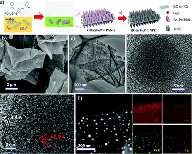
In addition to the rational control of the morphological features of GO@PANI nanosheets, the elemental composition of the nanosheets can easily be controlled by altering the composition of the aqueous layer. For example, the dopant HCl can be replaced by boric acid and telluric acid to produce PANI nanosheets that contain B/Te (Fig. S6 and S7†) and the corresponding heteroatom doped carbon nanosheets. Furthermore, it was found that iron cation – (Fe3+) and phosphate anion – (PO43−) anchored PANI nanosheets (GO@(Fe|P⊂PANI)) can easily be produced by using H3PO4 as an acid dopant and dissolving FeCl3 in the aqueous layer (Fig. 3a). Numerous free-standing and uniform nanosheets are evident in Fig. S8† and indicate the use of different acid dopants and the introduction of transition metal ions do not affect the 2D morphology. After direct pyrolysis under a hydrogen atmosphere, RG@(Fe2P⊂NPC) can be easily produced by using GO@(Fe|P⊂PANI) as a precursor.
The SEM and TEM images in Fig. 3b and c and S9† show uniform RG@(Fe2P⊂NPC) nanosheets and evenly distributed nanoparticles. Furthermore, the high-resolution TEM (HR-TEM) images in Fig. 3d and e clearly show a well-resolved lattice fringe with an interplanar distance of 0.20 nm, which can be ascribed to the (201) plane of Fe2P. At the edges of the Fe2P particles, several layers of carbon with an interplanar distance of 0.34 nm can be observed. The high-angle annular dark-field imaging scanning TEM image (HAADF STEM) and EDX elemental mapping images of C, N, Fe, and P for RG@(Fe2P⊂NPC) in Fig. 3f further verify the homogeneous distribution of the elements.
The XRD peaks of GO@(Fe|P⊂PANI) in Fig. 4a can be indexed to crystalline PANI,15 indicating that the introduction of ions into PANI does not affect the crystalline structure of PANI domains in the nanosheets (Fig. S3a†). The XRD peaks of RG@(Fe2P⊂NPC) in Fig. 4a can be indexed to crystalline Fe2P with lattice constants α = 5.867 Å and c = 3.458 Å (JCPDS no. 51-0943). The intense peaks located at 40.2, 44.1, 47.2, 52.8, 54.0, 54.6, 73.6, and 79.0° can be assigned to the (111), (201), (210), (002), (300), (211), (212), and (302) crystal planes, demonstrating that phase-pure Fe2P was successfully obtained after pyrolysis. Furthermore, a pronounced characteristic diffraction peak located at 25.2° was observed in the XRD spectrum of RG@(Fe2P⊂NPC), which can be ascribed to amorphous porous carbon. For comparison, pure Fe2P nanoparticles were also synthesized (Fig. S10 and S11†).
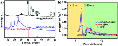 | ||
| Fig. 4 (a) XRD patterns of RG@(Fe2P⊂NPC), GO@(Fe|P⊂PANI) and the diffraction peaks referring to JCPDS card number 51-0943. (b) Pore size distribution of the samples using the DFT method. | ||
The X-ray photoelectron spectroscopy (XPS) spectra of RG@(Fe2P⊂NPC) were measured to confirm the chemical composition and valence states. The XPS survey scans (Fig. S12a†) reveal the presence of Fe, P, N, O, and C elements. The Fe 2p3/2 and Fe 2p1/2 couple peaks located at 707.1/720.2 eV and 711.2/724.0 eV can be ascribed to Fe2P and surface-oxidized ion species, respectively (Fig. S12b†). The P 2p1/2 and P 2p3/2 peaks at 130.2 and 129.3 eV can be attributed to Fe2P, and the P 2p peak at 133.3 eV can be attributed to residual phosphate (Fig. S12c†). This result is consistent with the result for the pure Fe2P nanoparticles that we prepared by a similar method (Fig. S12†). The N (2.59%), Fe (3.71%), and P (3.35%) contents based on XPS analysis for RG@(Fe2P⊂NPC) are summarized in Table S1.† The nitrogen physisorption measurement indicates that RG@(Fe2P⊂NPC) possesses a relatively high specific surface area of 240 m2 g−1 and a hierarchically porous structure (both micropores less than 2 nm and mesopores between 2 and 50 nm) in comparison with NPC and RG@NPC (Fig. 4b and S13; Table S2†). Furthermore, RG@(MoP⊂NPC), RG@(Co2P⊂NPC), and RG@(Ni12P5⊂NPC) (Fig. S14–S16†) were successfully prepared by means of only replacing FeCl3 by (NH4)2Mo4O13, CoCl2, and Ni(OAc)2, respectively, indicating the versatility of this procedure regarding different MP-embedded carbon nanosheets. All these results demonstrate that versatile MPs particle-anchored NPC can easily be fabricated and that the 2D morphology, crystalline character of the MPs, inorganic heterostructures,16 and hierarchical porous features of the nanosheets can be controlled rationally.
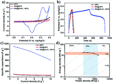
Integration of the multiple advantages of nitrogen doping, hierarchically porous structure, nanosheet morphology and carbon-wall-wrapped metal phosphides in such kinds of the as-prepared 2D hybrid materials holds promise for their application in electrochemical capacitors. RG@(Fe2P⊂NPC) was chosen as a typical example for electrochemical capacitor study. First, the cyclic voltammograms (CVs) of RG@(Fe2P⊂NPC) were measured at a sweep rate of 5 mV s−1 in 6 M KOH and were compared to the CVs of NPC, RG@NPC, and Fe2P (Fig. 5a, S17a and S18a–c†). The CVs of RG@NPC and NPC showed similar current densities, whereas the curve of RG@(Fe2P⊂NPC) displayed a much larger current density and typical redox current peaks corresponding to reversible reactions between Fe2+ and Fe3+. Based on the relevant literature,17 the possible reaction corresponding to the redox peaks is as following:
| Fe2+ + 2OH− → Fe(OH)2 | (3) |
| Fe(OH)2 + OH− ↔ FeOOH + H2O + e− | (4) |
The galvanostatic charge/discharge curves were measured at a current density of 1–10 A g−1 (Fig. 5b, S17b and S18d–f†). The specific capacitance of RG@(Fe2P⊂NPC) was calculated to be as high as 1098 F g−1, which is more than 10 times the capacitance values of NPC (90 F g−1), RG@NPC (106 F g−1), and Fe2P (44.3 F g−1) at 1 A g−1 (Fig. 5c). RG@(Fe2P⊂NPC) exhibited a high performance rate capability (Fig. 5c) and an extremely high specific capacitance of 611 F g−1 at 10 A g−1, outperforming state-of-the-art performance among porous carbon and MP-based supercapacitors (Table S3†).18 Furthermore, RG@(Fe2P⊂NPC) showed excellent cycling stability with 77.9% capacitance retention after 1000 cycles (Fig. S17c†). Energy and power densities are critical parameters for energy storage devices. Fig. 5d presents the Ragone plot of RG@(Fe2P⊂NPC) related to energy and power densities. The supercapacitor based on RG@(Fe2P⊂NPC) exhibited a maximum energy density of 18.7 W kg−1 at 175.1 W kg−1, which is comparable to the maximum energy densities of most heteroatom-doped carbon-based electrodes.19 Nyquist plots and equivalent circuits (Fig. S19 and Table S4†) of these electrodes reveal that RG@(Fe2P⊂NPC) exhibited the lowest charge-transfer resistance (0.25 Ω) among the as-prepared materials (RG@NPC: 0.45 Ω, NPC: 0.61 Ω, Fe2P: 1032 Ω), benefiting from the high conductivity of porous carbons and the long-distance conductivity of graphene layers. Thus, the good conductivity, hierarchically porous structure, and the synergistic effect between Fe2P and NPC may be effectively combined together to contribute to the outstanding supercapacitor performance.20
MPs have recently been widely investigated because of their potential for the high performance electrochemically catalyzed hydrogen evolution reaction (HER).21 Therefore, the electrocatalytic HER activity of the obtained RG@(MP⊂NPC)s in 0.5 M H2SO4 was examined. The iR correction was applied to all electrochemical measurements because of ohmic resistance during measurement. The polarization curves and calculated Tafel slopes of the as-prepared materials are depicted in Fig. S20a and b.† Table S6† shows that RG@(Fe2P⊂NPC) exhibited the lowest onset overpotential (45 mV), the lowest overpotentials (102 mV at 10 mA cm−2; 191 mV at 100 mA cm−2), and the smallest Tafel slope (61 mV dec−1) thereby suggesting that the HER occurs on the surface of RG@(Fe2P⊂NPC) according to the Volmer–Heyrovsky mechanism.22 The polarization curves (Fig. S20d†) of the RG@(Fe2P⊂NPC) cathode before and after accelerated degradation testing for 3000 continuous cycles (sweeping the potential in a range of −500 mV to +200 mV versus RHE at a rate of 100 mV s−1). The electrode exhibited minimal degradation after 3000 cycles, with an overpotential increase of only 10 ± 1 mV, to achieve current densities of 10 and 100 mA cm−2, respectively. These results were comparable to those reported for Fe2P-based catalysts and other MP-based catalysts (Table S7†).23 The superior HER performance of RG@(Fe2P⊂NPC) compared to that of RG@(MP⊂NPC) can be further assessed by electrochemical impedance spectroscopy (Fig. S20c†) and calculated charge-transfer resistance (Table S5†) based on a two-time-constant model (Fig. S21†). The HER performance of the as-prepared materials can be further optimized by controlling different parameters such as pyrolysis temperature, particle size, and MP content.
Bimetallic nanoparticle-based nanomaterials have exhibited excellent potential as efficient electrochemical catalysts for the HER,24 CO2 reduction reaction,25 oxygen evolution reaction (OER),26 and oxygen reduction reaction (ORR).27 As a proof-of-concept, Fe2P and Co2P co-embedded 2D NPC (denoted as RG@(Fe2P|Co2P⊂NPC)) was further prepared through the same procedure by adding both FeCl3 and CoCl2 to the aqueous layer. The HR-TEM image in Fig. 6a clearly shows a well-resolved lattice fringe with interplanar distances of 0.20 nm and 0.44 nm, corresponding to the (201) plane of Fe2P and the (101) plane of Co2P, respectively. This is consistent with the XRD pattern and XPS result of RG@(Fe2P|Co2P⊂NPC) (Fig. S22 and S23†). The HAADF STEM image and EDX elemental mapping further illustrate that C, N, Fe, Co, and P are uniformly distributed in the bimetallic phosphide-based 2D hybrid (Fig. 6b).
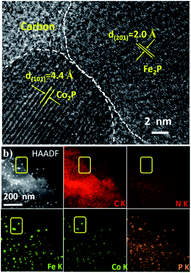 | ||
| Fig. 6 (a) High resolution TEM image, (b) HAADF STEM image and elemental mapping of RG@(Co2P|Fe2P⊂NPC). | ||
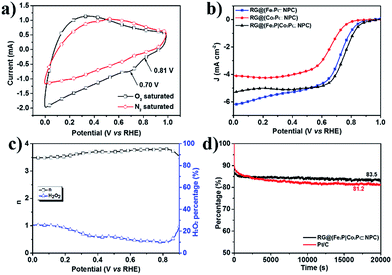
The electrocatalytic properties of RG@(MP⊂NPC) for the ORR was subsequently evaluated under alkaline conditions (0.1 M KOH). First, the CV of RG@(Fe2P|Co2P⊂NPC) in O2-saturated 0.1 M KOH revealed an ORR peak potential of 0.70 V versus RHE (Fig. 7a), which is 5–6 mV higher than those of RG@NPC and single MP-embedded 2D NPC (Fig. S24†). According to the LSV curves under 1600 rpm (Fig. 7b), RG@(Fe2P|Co2P⊂NPC) showed an excellent onset potential of 0.8 V and a half-wave potential of 0.78 V, which are superior to those of RG@(Fe2P⊂NPC) and RG@(Co2P⊂NPC). The half-wave potential difference between RG@(Fe2P|Co2P⊂NPC) and Pt/C was found to be only 49 mV (Fig. S26b†). According to the rotating ring-disk electrode experiment (Fig. S26a†), a four-electron transfer (n ≈ 3.78 at 0.7 V) mechanism with a low yield of H2O2 (Fig. 7c) can be calculated (eqn (1) and (2)). In addition, the durability of RG@(Fe2P|Co2P⊂NPC) was tested at a constant voltage of 0.45 V for 20![[thin space (1/6-em)]](https://www.rsc.org/images/entities/char_2009.gif) 000 s (Fig. 7d). Notably, it exhibited a high relative current (83.5%) that persisted after 20
000 s (Fig. 7d). Notably, it exhibited a high relative current (83.5%) that persisted after 20![[thin space (1/6-em)]](https://www.rsc.org/images/entities/char_2009.gif) 000 s, which is higher than that of Pt/C (81.2%). This may attributed to the fact that the MPs were well wrapped by the carbon layer. Compared with the ORR performance of the as-prepared single MP-anchored carbon nanosheets (Fig. S24 and S25†), RG@(Fe2P|Co2P⊂NPC) showed the best ORR activity. This may attributed to the synergistic effect between bimetallic nanoparticles. Generally, the superior electrocatalytic activity of the as-prepared RG@(MPs⊂NPC)s are attributable to the following causes: (1) the small and uniformly distributed crystallized MPs produce large active sites for the HER and ORR; (2) the 2D morphology and strong interactions between the RG, NPC, and MPs substantially increase the electrical conductivity, thereby enhancing electron transfer.
000 s, which is higher than that of Pt/C (81.2%). This may attributed to the fact that the MPs were well wrapped by the carbon layer. Compared with the ORR performance of the as-prepared single MP-anchored carbon nanosheets (Fig. S24 and S25†), RG@(Fe2P|Co2P⊂NPC) showed the best ORR activity. This may attributed to the synergistic effect between bimetallic nanoparticles. Generally, the superior electrocatalytic activity of the as-prepared RG@(MPs⊂NPC)s are attributable to the following causes: (1) the small and uniformly distributed crystallized MPs produce large active sites for the HER and ORR; (2) the 2D morphology and strong interactions between the RG, NPC, and MPs substantially increase the electrical conductivity, thereby enhancing electron transfer.
Conclusions
In summary, we demonstrated an interfacial engineering method for the rational synthesis of 2D PANI nano-array and corresponding nitrogen-doped porous carbon nanosheets. Not only was it easy to produce a sandwich-like 2D morphology, but also the thickness, anchored cations and anions, and different metal phosphides were easily and rationally engineered by controlling the composition of the aqueous layer. The novel structural features of these hybrids enabled outstanding electrochemical performance. We believe that this interfacial approach can be extended to the controllable synthesis of various 2D materials coupled sandwich-like hybrid materials with potential application in a wide range of areas. Such an interfacial method can be used to fabricate various types of heteroatom-doped porous carbon nanosheets and MP-anchored carbon nanosheets. Moreover, it can be used to produce versatile nanoparticles, such as transition metal carbide (Fig. S27†) anchored porous carbon nanosheets for a broad range of applications in the field of energy storage and conversion.Acknowledgements
C. L. and S. L. contributed equally to this work. This work was financially supported by the 973 Programs of China (2013CBA01602), National Natural Science Foundation of China (51403126 and 61306018), the Shanghai Committee of Science and Technology (15JC1490500), Shanghai Municipal Natural Science Foundation (16JC1400703), ERC Grant on 2DMATER, UP-GREEN and EU Graphene Flagship.Notes and references
- (a) A. G. MacDiarmid, Angew. Chem., Int. Ed., 2001, 40, 2581 CrossRef CAS; (b) O. Bubnova, Z. U. Khan, A. Malti, S. Braun, M. Fahlman, M. Berggren and X. Crispin, Nat. Mater., 2011, 10, 429 CrossRef CAS PubMed; (c) J. E. Yoo, K. S. Lee, A. Garcia, J. Tarver, E. D. Gomez, K. Baldwin, Y. Sun, H. Meng, T. Q. Nguyen and Y. L. Loo, Proc. Natl. Acad. Sci. U. S. A., 2010, 107, 5712 CrossRef CAS PubMed; (d) J. Heinze, B. A. Frontana-Uribe and S. Ludwigs, Chem. Rev., 2010, 110, 4724 CrossRef CAS PubMed.
- (a) J. Huang and R. B. Kaner, J. Am. Chem. Soc., 2004, 126, 851 CrossRef CAS PubMed; (b) J. C. Michaelson and A. J. McEvoy, J. Chem. Soc., Chem. Commun., 1994, 79 RSC.
- (a) G. D. Fu, J. P. Zhao, Y. M. Sun, E. T. Kang and K. G. Neoh, Macromolecules, 2007, 40, 2271 CrossRef CAS; (b) P. Anilkumar and M. Jayakannan, Macromolecules, 2008, 41, 7706 CrossRef CAS.
- J. Huang, S. Virji, B. H. Weiller and R. B. Kaner, J. Am. Chem. Soc., 2003, 125, 314 CrossRef CAS PubMed.
- L. Zhang, Z. D. Zujovic, H. Peng, G. A. Bowmaker, P. A. Kilmartin and J. Travas-Sejdic, Macromolecules, 2008, 41, 8877 CrossRef CAS.
- S. Li, D. Wu, C. Cheng, J. Wang, F. Zhang, Y. Su and X. Feng, Angew. Chem., Int. Ed., 2013, 52, 12105 CrossRef CAS PubMed.
- (a) Z. Wei, Z. Zhang and M. Wan, Langmuir, 2002, 18, 917 CrossRef CAS; (b) Z. Wei and M. Wan, J. Appl. Polym. Sci., 2003, 87, 1297 CrossRef CAS; (c) H. Qiu, M. Wan, B. Matthews and L. Dai, Macromolecules, 2001, 34, 675 CrossRef CAS.
- (a) Q. Hao, H. Wang, X. Yang, L. Lu and X. Wang, Nano Res., 2011, 4, 323–333 CrossRef CAS; (b) J. Zhu, M. Chen, H. Qu, X. Zhang, H. Wei, Z. Luo, H. A. Colorado, S. Wei and Z. Guo, Polymer, 2012, 53, 5953–5964 CrossRef CAS; (c) Y. Jin, S. Huang, M. Zhang and M. Jia, Synth. Met., 2013, 168, 58–64 CrossRef CAS.
- (a) X. Zhuang, Y. Mai, D. Wu, F. Zhang and X. Feng, Adv. Mater., 2015, 27, 403 CrossRef CAS PubMed; (b) X. Zhuang, F. Zhang, D. Wu, N. Forler, H. Liang, M. Wagner, D. Gehrig, M. R. Hansen, F. Laquai and X. Feng, Angew. Chem., Int. Ed., 2013, 52, 9668 CrossRef CAS PubMed; (c) X. Zhuang, F. Zhang, D. Wu and X. Feng, Adv. Mater., 2014, 26, 3081 CrossRef CAS PubMed; (d) X. Zhuang, D. Gehrig, N. Forler, H. Liang, M. Wagner, M. R. Hansen, F. Laquai, F. Zhang and X. Feng, Adv. Mater., 2015, 27, 3789 CrossRef CAS PubMed; (e) S. Liu, J. Zhang, R. Dong, P. Gordiichuk, T. Zhang, X. Zhuang, Y. Mai, F. Liu, A. Herrmann and X. Feng, Angew. Chem., Int. Ed., 2016, 55, 12516 CrossRef CAS PubMed; (f) K. Yuan, X. Zhuang, H. Fu, G. Brunklaus, M. Forster, Y. Chen, X. Feng and U. Scherf, Angew. Chem., Int. Ed., 2016, 55, 6858 CrossRef CAS PubMed; (g) Y. Su, Z. Yao, F. Zhang, H. Wang, Z. Mics, E. Cánovas, M. Bonn, X. Zhuang and X. Feng, Adv. Funct. Mater., 2016, 26, 5893–5902 CrossRef CAS.
- (a) S. Najmaei, Z. Liu, W. Zhou, X. Zou, G. Shi, S. Lei, B. I. Yakobson, J.-C. Idrobo, P. M. Ajayan and J. Lou, Nat. Mater., 2013, 12, 754 CrossRef CAS PubMed; (b) S. Ithurria, M. Tessier, B. Mahler, R. Lobo, B. Dubertret and A. L. Efros, Nat. Mater., 2011, 10, 936 CrossRef CAS PubMed; (c) X. Huang, X. Qi, F. Boey and H. Zhang, Chem. Soc. Rev., 2012, 41, 666 RSC.
- (a) H. Wang, J. T. Robinson, G. Diankov and H. Dai, J. Am. Chem. Soc., 2010, 132, 3270 CrossRef CAS PubMed; (b) S. Chen, J. Zhu, X. Wu, Q. Han and X. Wang, ACS Nano, 2010, 4, 2822 CrossRef CAS PubMed; (c) J. Y. Son, Y.-H. Shin, H. Kim and H. M. Jang, ACS Nano, 2010, 4, 2655 CrossRef CAS PubMed; (d) C. X. Guo, H. B. Yang, Z. M. Sheng, Z. S. Lu, Q. L. Song and C. M. Li, Angew. Chem., Int. Ed., 2010, 49, 3014 CrossRef CAS PubMed; (e) A. Cao, Z. Liu, S. Chu, M. Wu, Z. Ye, Z. Cai, Y. Chang, S. Wang, Q. Gong and Y. Liu, Adv. Mater., 2010, 22, 103 CrossRef CAS PubMed; (f) Z. Huang, C. Lv, Z. Chen, Z. Chen, F. Tian and C. Zhang, Nano Energy, 2015, 12, 666 CrossRef CAS.
- (a) P. S. Toth, M. Velický, M. A. Bissett, T. J. A. Slater, N. Savjani, A. K. Rabiu, A. M. Rakowski, J. R. Brent, S. J. Haigh, P. O'Brien and R. A. W. Dryfe, Adv. Mater., 2016, 28, 8256–8264 CrossRef CAS PubMed; (b) P. S. Toth, Q. M. Ramasse, M. Velicky and R. A. W. Dryfe, Chem. Sci., 2015, 6, 1316–1323 RSC.
- (a) F. Bonaccorso, L. Colombo, G. Yu, M. Stoller, V. Tozzini, A. C. Ferrari, R. S. Ruoff and V. Pellegrini, Science, 2015, 347, 1246501 CrossRef PubMed; (b) S. Eigler and A. Hirsch, Angew. Chem., Int. Ed., 2014, 53, 7720 CrossRef CAS PubMed.
- L. Mazerolles, S. Folch and P. Colomban, Macromolecules, 1999, 32, 8504 CrossRef CAS.
- J. P. Pouget, M. E. Jozefowicz, A. J. Epstein, X. Tang and A. G. MacDiarmid, Macromolecules, 1991, 24, 779 CrossRef CAS.
- P. S. Toth, M. Velický, M. A. Bissett, T. J. Slater, N. Savjani, A. K. Rabiu, A. M. Rakowski, J. R. Brent, S. J. Haigh and P. O'Brien, Adv. Mater., 2016, 28, 8256–8264 CrossRef CAS PubMed.
- (a) D. Wang, L. B. Kong, M. C. Liu, Y. C. Luo and L. Kang, Chem.–Eur. J., 2015, 21, 17897–17903 CrossRef CAS PubMed; (b) X. Chen, M. Cheng, D. Chen and R. Wang, ACS Appl. Mater. Interfaces, 2016, 8, 3892–3900 CrossRef CAS PubMed.
- (a) J. Chang, M. Jin, F. Yao, T. H. Kim, V. T. Le, H. Yue, F. Gunes, B. Li, A. Ghosh, S. Xie and Y. H. Lee, Adv. Funct. Mater., 2013, 23, 5074 CrossRef CAS; (b) Z. Lei, L. Lu and X. S. Zhao, Energy Environ. Sci., 2012, 5, 6391 RSC; (c) A. Sumboja, C. Y. Foo, X. Wang and P. S. Lee, Adv. Mater., 2013, 25, 2809 CrossRef CAS PubMed; (d) J. Xu, K. Wang, S.-Z. Zu, B.-H. Han and Z. Wei, ACS Nano, 2010, 4, 5019 CrossRef CAS PubMed; (e) K. Yuan, Y. Xu, J. Uihlein, G. Brunklaus, L. Shi, R. Heiderhoff, M. Que, M. Forster, T. Chasse, T. Pichler, T. Riedl, Y. Chen and U. Scherf, Adv. Mater., 2015, 27, 6714 CrossRef CAS PubMed.
- (a) Q. Wang, J. Yan and Z. J. Fan, Energ Environ. Sci., 2016, 9, 729 RSC; (b) L. Liu, Z. Niu and J. Chen, Chem. Soc. Rev., 2016, 45, 4340 RSC.
- (a) S. He, H. Hou and W. Chen, J. Power Sources, 2015, 280, 678–686 CrossRef CAS; (b) S. He and W. Chen, Nanoscale, 2015, 7, 6957–6990 RSC; (c) J. Masa, W. Xia, M. Muhler and W. Schuhmann, Angew. Chem., Int. Ed., 2015, 54, 10102 CrossRef CAS PubMed.
- (a) Y. Shi and B. Zhang, Chem. Soc. Rev., 2016, 45, 1529 RSC; (b) M. Sun, H. Liu, J. Qu and J. Li, Adv. Energy Mater., 2016, 6, 1600087 CrossRef.
- B. E. Conway and B. V. Tilak, Electrochim. Acta, 2002, 47, 3571 CrossRef CAS.
- (a) Q. Liu, J. Q. Tian, W. Cui, P. Jiang, N. Y. Cheng, A. M. Asiri and X. P. Sun, Angew. Chem., Int. Ed., 2014, 53, 6710 CrossRef CAS PubMed; (b) P. Xiao, M. A. Sk, L. Thia, X. M. Ge, R. J. Lim, J. Y. Wang, K. H. Lim and X. Wang, Energy Environ. Sci., 2014, 7, 2624 RSC; (c) Z. C. Xing, Q. Liu, A. M. Asiri and X. P. Sun, Adv. Mater., 2014, 26, 5702 CrossRef CAS PubMed.
- (a) Y. Tan, H. Wang, P. Liu, Y. Shen, C. Cheng, A. Hirata, T. Fujita, Z. Tang and M. Chen, Energy Environ. Sci., 2016, 9, 2257 RSC; (b) Z. F. Huang, J. Song, K. Li, M. Tahir, Y. T. Wang, L. Pan, L. Wang, X. Zhang and J. J. Zou, J. Am. Chem. Soc., 2016, 138, 1359 CrossRef CAS PubMed; (c) Q. Lu, G. S. Hutchings, W. Yu, Y. Zhou, R. V. Forest, R. Tao, J. Rosen, B. T. Yonemoto, Z. Cao, H. Zheng, J. Q. Xiao, F. Jiao and J. G. Chen, Nat. Commun., 2015, 6, 6567 CrossRef CAS PubMed.
- (a) S. Rasul, D. H. Anjum, A. Jedidi, Y. Minenkov, L. Cavallo and K. Takanabe, Angew. Chem., Int. Ed., 2015, 54, 2146 CrossRef CAS PubMed; (b) X. Sun, Q. Zhu, X. Kang, H. Liu, Q. Qian, Z. Zhang and B. Han, Angew. Chem., Int. Ed., 2016, 55, 6771 CrossRef CAS PubMed.
- (a) R. Zhang, C. Zhang and W. Chen, J. Mater. Chem. A, 2016, 4, 18723 RSC; (b) B. Ni and X. Wang, Chem. Sci., 2015, 6, 3572 RSC.
- (a) Y.-Z. Chen, C. Wang, Z.-Y. Wu, Y. Xiong, Q. Xu, S.-H. Yu and H.-L. Jiang, Adv. Mater., 2015, 27, 5010 CrossRef CAS PubMed; (b) Z. Li, M. Shao, L. Zhou, Q. Yang, C. Zhang, M. Wei, D. G. Evans and X. Duan, Nano Energy, 2016, 25, 100 CrossRef.
Footnote |
| † Electronic supplementary information (ESI) available. See DOI: 10.1039/c6ta09278k |
| This journal is © The Royal Society of Chemistry 2017 |

