 Open Access Article
Creative Commons Attribution 3.0 Unported Licence
Degradation of radiation grafted hydroxide anion exchange membrane immersed in neutral pH: removal of vinylbenzyl trimethylammonium hydroxide due to oxidation
Richard
Espiritu
 ab,
Bernard T.
Golding
c,
Keith
Scott
a and
Mohamed
Mamlouk
 *a
*a
aSchool of Chemical Engineering and Advanced Materials, Merz Court, Newcastle University, Newcastle upon Tyne, NE1 7RU, UK. E-mail: mohamed.mamlouk@ncl.ac.uk
bDepartment of Mining, Metallurgical and Materials Engineering, University of the Philippines Diliman, Quezon City 1101, Philippines
cSchool of Chemistry, Bedson Building, Newcastle University, Newcastle upon Tyne, NE1 7RU, UK
First published on 12th December 2016
Abstract
Anion exchange membranes (AEMs) fabricated using polyethylene (PE) and ethylene tetrafluoroethylene films are subjected to degradation tests in deionised water for electrolyser/fuel cell operation. After the degradation test, the decrease in ion-exchange capacity (IEC) of the AEM, hence decrease in ionic conductivity, is found to be influenced by the applied gamma radiation dose rate. The use of high radiation dose rate produces membranes with improved stability in terms of % IEC loss due to shorter, more uniformly distributed vinylbenzyl chloride (VBC) grafts. For LDPE-based AEMs, increasing the applied radiation dose rate during grafting from 30 to 2000 Gy h−1 significantly reduces AEM % IEC loss from 38 to 11%, respectively. Analyses of both the aged functionalised membranes and their resulting degradation products confirm the loss of not only the functional group, but also the VBC group, which have not been reported previously in the literature. Oxidation reactions taking place in solutions close to neutral can be the main contributor to the IEC loss in contrast to the widely reported E2 or SN2 attack on the head group in high alkalinity solutions. We therefore propose parallel degradation mechanisms to head group loss of AEM that involves peroxide radicals which is more dominant at low alkalinity solutions.
1. Introduction
Among the different types of fuel cell systems, proton-exchange membrane fuel cells (PEMFCs) and alkaline fuel cells (AFCs) are the most studied for practical service applications, particularly in low temperature regimes of operating conditions. With the development of solid anion-exchange membranes (AEMs), working in alkaline anion-exchange membrane environment (AAEM) has several advantages over proton exchange membrane environment (PEM) for fuel cell and water electrolyser (PEMWE), namely, faster oxygen reduction reaction (ORR) and oxygen evolution reaction (OER) under alkaline conditions than in their acidic counterpart therefore providing lower activation losses,1,2 feasible use of non-noble metal catalysts3–5 and cheaper cell components due to a less corrosive environment.6,7 Furthermore, with the use of solid AEM, electrolyte leaking and carbonate precipitation are prevented due to the effective separation of the fuel and the oxidant8 which also allow operation under differential pressure across the membrane.Alkaline AEMs are solid polymer electrolytes that contain positive ionic groups, typically quaternary ammonium groups: –N+(CH3)3, and mobile negatively charged anions, usually OH−.9,10 There have been several classes of AEMs fabricated for AFC operations reported in literature. The most common class of AEMs is those based on quaternary ammonium groups11,12 due to their appreciable stability in an alkaline environment.13,14
We have reported the ionic conductivity and fuel cell performance of several benzylammonium and sulfonium head groups for AEMs and found that trimethylamine (TMA)-functionalised ionomers showed superior ORR performance and higher ionic conductivities in comparison to other studied head groups including 1,4-diazabicyclo[2.2.2]octane (DABCO).10,15 Our report2 showed an increase of around 60% of the power density at 0.4 V when TMA was used instead of N,N,N′,N′-tetramethyl-1,6-hexanediamine (TMHDA) at 60 °C. Furthermore, TMA-functionalised vinylbenzyl chloride (radiation) grafted on low-density polyethylene backbone (LDPE-g-VBC-TMA) showed low activation energy of 12 kJ mol−1 for OH− ionic conductivity2 close to the reported value for H+ conductivity in Nafion3 with OH− through plane conductivity of 0.13 S cm−1 at 80 °C and 100% RH.2 These (LDPE-g-VBC-TMA) AEMs have superior fuel cell peak power densities at a high potential of 500 mV, one of the highest reported in the literature for AAEMFCs of 823 mW cm−2 under oxygen (atm) and 506 mW cm−2 under air (1 bar gauge) at 60 °C.16
While AEMFCs has shown excellent ionic conductivity and cell performance, their chemical and thermal stability for long term service life remains a challenge. Alkaline stability and degradation of AEMs are mainly assessed in the purview of cation stability. The literature has abundantly discussed mechanisms of the degradation of AEMs, namely, Hofmann elimination, nucleophilic substitution and formation of ylide derivatives.17–26 Hofmann elimination is when OH− ions attack a β-hydrogen atom (with respect to N) of the cation which leads to the elimination of a tertiary amine from the neighbouring carbon.18,20,21 Nucleophilic substitution involves OH− ions acting as a strong nucleophile, which can either (1) attack the α-carbon atom of the cation converting the quaternary ammonium group to a tertiary amine and releasing an alcohol or (2) attack the benzylic carbon atom causing the detachment of a tertiary amine.19,22,24 Lastly, the ylide formation route is through OH− ions abstracting a proton (α-hydrogen) from a methyl group producing a nitrogen ylide intermediate which transforms to tertiary amine and water.23,25,26 These ylide intermediates can further undergo degradation through the Stevens rearrangement or Sommelet–Hauser mechanism,17,27–29 selectivity of which is dependent on the electronic properties of the substituents attached to the aromatic ring, steric effects and the type of solvent used.29 These three degradation mechanisms can occur in parallel, which can lead to a combination of degradation products. It is thus important to synthesise membranes with chemical structures capable of circumventing these degradation mechanisms to ensure long term stability of AEMs.
The chemical and thermal stability of AEMs greatly depend on the nature of the polymer backbone and on the type of functional group that enables the transfer of hydroxide ions.30 The use of hydrocarbon-based polymer backbones, like polyether sulfone (PES) and polyphenylene oxide (PPO), for AEMs offer advantages, namely, low cost, commercial availability and structures that are amenable for tethering pendant groups.31 However, even though PES-based AEMs are tolerant to highly basic environment, the polymer backbone gradually degrades in alkaline medium when quaternised with ammonium functional group.22,32 The PPO-based AEM, on the other hand, undergoes backbone degradation by chain scission via hydrolysis of ether bonds.33,34 The fluorinated base polymers have emerged to be the preferred polymer backbone for AEM preparation owing to its inherent inert properties and electrochemical and thermal stability due to the presence of strong electron-withdrawing fluorine atom.35 However, it has been reported that partially fluorinated polymers like PVDF-based AEMs are known to degrade in alkaline media via dehydrofluorination.36,37
The fact that novel fluorocarbon-type AEMs are still unstable under strong basic conditions6,38 suggests that the functional ion-exchange groups rather than the cross-linked polymer network undergoes degradation. Therefore, it can be assumed that the alkaline stability of an AEM is given by the stability of the weakest link, which is generally considered to be the head group. Among the different type of positive ionic groups, the quaternary ammonium ions possess a considerably higher thermal and chemical stability compared to phosphonium or sulfonium groups.20 However, it was reported that phosphonium groups have demonstrated their potential by exhibiting greater stability towards attack by hydroxide ion than the more conventional quaternary ammonium.39
The attachment of the head group to the polymer backbone can be typically achieved through benzyl or phenyl bonds. Benzyl-trimethylammonium (benzyl-TMA) is far more stable than its phenyl equivalent.14 90% of benzyl-TMA was found to be stable after 29 days alkaline treatment compared to only 30% for phenyl-TMA.25 Among the several studied quaternary ammonium head groups, benzyl-TMA and benzyl-DABCO showed the highest stability in 2 M KOH at 160 °C (under N2) with half-time disintegration of 29 and 42 min, respectively.40
The chemical stability of AEMs in the OH− form, particularly at high temperatures, poses a critical challenge that limits the wide scale use of AEMFCs. In our previous publication,41 we have successfully demonstrated the long term stability of the fabricated polyethylene-based AEMs for AAEMFCs operating at temperature of up to 80 °C. We have shown that the degradation rate is strongly dependent on oxidant concentration, where degradation rate under oxygen (atm) was more than 4 times faster than that under nitrogen. However, limited chemical analysis has been conducted regarding the chemical stability of AEMs. Thus, a more fundamental understanding of the chemical stability of AEMs is required to adequately design robust solid-state AEMFCs and electrolysers.23 Degradation tests of membranes having quaternary ammonium groups reported in literature were all performed in high alkaline concentrations42,43 and elevated temperature.14,23,44 This study is the first attempt to illustrate the degradation of the OH− exchanged AEM stored in deionised water, which is the usual medium present in electrolyser and fuel cell operations. Furthermore, the majority of the published work assessed membrane stability by measuring the decrease in its weight, ion exchange capacity and ionic conductivity with time.23,42,43,45–49 However, very limited research has been done to analyse the decomposition products. This is partially due to the insoluble nature of some of these products,50 limiting the techniques available for chemical analysis needed to identify their structure. Due to such difficulties, we have gathered results from several chemical analyses to determine the identity of the degradation products. Most importantly, all of the available literature have so far reported that the degradation of AEMs is due to the removal of the ion-carrying functional groups and not the graft VBC.6,11,13,19,20,40,51,52 This research is the first to report that the degradation of the AEMs is not only due to the removal of the functional group, but also attributed to the loss of the benzene ring, in the AEMs we have synthesised and investigated. Such findings will have a significant impact on the way we design and fabricate AEMs in order to obtain excellent thermal and chemical stability properties.
2. Mechanism of AEM degradation
For the TMA-functionalised membranes, the attachment of TMA to the benzylic chloride during functionalisation does not produce β-hydrogens, thus the Hofmann elimination route can be conveniently disregarded.43,49,53 When the Hofmann elimination is impossible, nucleophilic substitution proceeds preferably towards the release of TMA rather than producing the benzyl-dimethylamine unit23,40,54 as shown in Scheme 1. This is because nucleophilic substitution reaction is generally favourable at a benzylic methylene carbon and TMA is a good leaving group.55,56 The reaction consequently leaves behind a benzylic alcohol54 that could readily transforms to dibenzylic ether, and together with TMA, are the major decomposition products.57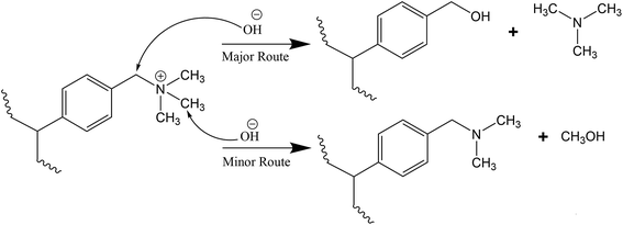 | ||
| Scheme 1 Degradation mechanism of OH− ion attack on TMA cation group via nucleophilic substitution.54 | ||
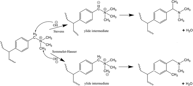
Stevens rearrangement for the benzyl-TMA group in basic media involves abstraction of the relatively acidic proton from the methylene group connecting the aromatic group and the TMA to form an ylide. This ylide intermediate undergoes rearrangement to produce a tertiary amine and water as final products (Scheme 2).28 Similar to the Stevens rearrangement, the Sommelet–Hauser mechanism also involves proton abstraction by OH− ions, however the attack is on a methyl group attached to the quaternary nitrogen atom and the resulting carbanion attacks the ortho-position of the aromatic ring (Scheme 2).29
For the benzyl-TMA cation, Stevens rearrangement is the only ylide reaction observed as the OH− ion prefers the proton attached to the methylene group connecting the aromatic ring and the TMA, rather than a methyl attached to the quaternary nitrogen atom.27,28 However, recent studies have suggested that this ylide reaction pathway is reversible and does not lead to cation degradation,13,26,46,58 while DFT calculations suggest that both pathways (ylide formation and OH− attack) have the same overall barrier25 and in close to neutral pH (low OH− concentration) it is expected that the ylide formation will be more dominant.
Unlike the TMA-functionalised membranes, the reaction between DABCO and VBC results in the presence of β-carbons. Even though DABCO has β-hydrogens, its structure does not allow the stereoelectronics necessary for a Hofmann elimination mechanism.19,21,24 However, the mono-quaternised DABCO can undergo a nucleophilic displacement reaction causing the release of DABCO to the solution as shown in Scheme 3.23,40
 | ||
| Scheme 3 Degradation mechanism by nucleophilic substitution of OH− ion on the methylene group attached to DABCO.40 | ||
3. Experimental
3.1 Materials
The low-density polyethylene films were sourced from British Polythene Industries plc. The ethylene-tetrafluoroethylene films were procured from Nowoflon Kunststoffprodukte GmbH while the high-density polyethylene films were obtained from Metal Box Co. All commercial polymer films were used as received. Vinylbenzyl chloride (mixture of 3- and 4-isomers, 97%), trimethylamine (45% in water) and 1,4-diazabicyclo[2.2.2]octane were all acquired from Sigma-Aldrich. Toluene solvent, potassium hydroxide pellets, acetone, sulfuric acid, methanol and sodium chloride were all analytical reagent grade and were used as received.3.2 Anion exchange membrane preparation
The AEMs were synthesised as previously reported16,41 using low-density polyethylene (LDPE), high-density polyethylene (HDPE) and ethylene-tetrafluoroethylene (ETFE) as base polymers with vinylbenzyl chloride (VBC) as the graft monomer. The PE-g-VBC copolymer was prepared by immersing the PE films in nitrogen purged 31/26/45 by volume VBC/toluene/methanol solution placed in a screw-cap vial. Samples were sent to Synergy Health plc (Wiltshire, UK) for mutual gamma radiation grafting. The irradiation was carried out under known dose rate and total radiation dose for a predetermined time. On the other hand, the ETFE-g-VBC membrane was produced by irradiating first the ETFE film using an electron-beam source (4.5 MeV) to a total radiation dose of 70 kGy and was subsequently immersed in N2-purged VBC monomer solution. The grafted membranes obtained were washed thoroughly with acetone to completely remove VBC homopolymers. To produce the AEM, trimethylamine (TMA) was used to impart functionality to the PE-g-VBC (Scheme 4) and ETFE-g-VBC copolymers. Another set of LDPE-based membranes was prepared but functionalised with DABCO. Scheme 4 shows an idealised schematic of the preparation of polyethylene-based AEM functionalised with TMA.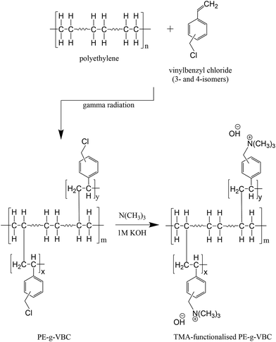 | ||
| Scheme 4 Representative schematic of polyethylene-based AEM synthesis.41 | ||
3.3 Membrane stability tests
After the stability tests, the sealed bottles were allowed to cool to room temperature and the aged membranes were extracted and analysed separately. The degradation solutions, on the other hand, were visually examined and presence of suspended solid precipitates were separated from the solution using Eppendorf 5804R Centrifuge. The clear solution was then allowed to dry at 50 °C using a MTI Model DZF-6020-FP vacuum oven for recovery of solid precipitates.
3.4 Characterisation of the membrane and the degradation products
 | (1) |
3.4.3.1 SEM analysis. Scanning electron microscopy (SEM) coupled with Energy-dispersive X-ray spectroscopy (EDX) was performed using a JEOL JSM-5300LV machine equipped with RONTEC UHV Dewar Detector.
3.4.3.2 Nuclear Magnetic Resonance (NMR) spectroscopy. Solid-state (13C and 15N) NMR analysis employing magic-angle spinning with cross-polarisation (CP-MAS) of the AEMs before and after degradation and the resulting degradation products were performed using tetramethylsilane and nitromethane as chemical shift references, respectively. For the solid-state 17O NMR analysis of the membrane, direct-excitation (DE-MAS) was employed with water as the chemical shift reference. All solid-state (13C, 15N and 17O) NMR spectra obtained with two-pulse phase-modulated (TPPM) decoupling were acquired using a Varian VNMRS Spectrometer at the EPSRC National Solid-State NMR Service in Durham University, UK. The enriched water–17O (70–75.9 atom% 17O, Aldrich) was used to prepare 0.1 M NaOH solution in a glove box by adding appropriate amount of Na. The membrane was immersed in this solution for 2 months at 60 °C. The membrane was rinsed with deionised water and dried in air in a vacuum oven at 50 °C. The isotope-labelled degradation solution was subjected to solution NMR analysis using a Bruker 500 Avance III HD spectrometer to obtain the 17O NMR spectra.
3.4.3.3 Fourier-transform infrared (FTIR) spectroscopy. Determination of chemical structure and presence of functional groups were performed using a Varian 800 FT-IR Spectrometer with scan range of 4000 to 500 cm−1 equipped with a Pike Technologies diamond crystal plate Attenuated Total Reflectance (ATR) unit.
4. Results and discussion
4.1 Stability of LDPE-g-VBC copolymer and the fabricated membrane
The stability of the fabricated membranes was assessed by measuring the IEC of the un-exchanged (Cl− form) membranes before and after immersing the membranes in deionised water at 60 °C for 3 months. Table 1 indicates the stability of the synthesised membranes having the same degree of grafting (DOG) wherein IEC did not change after the stability test. Both the DABCO- and TMA-functionalised membranes in their unexchanged (Cl−) forms were found to be stable at 60 °C for 3 months with no change in their IEC. The solutions wherein the membranes were immersed were also oven dried and no solid precipitates were recovered indicating that there was no soluble degradation products of the membrane.| Membrane code | Radiation dose rate (Gy h−1) | DOG (%) | Functionality | IEC (mmol g−1) | |
|---|---|---|---|---|---|
| Initial | After 3 months | ||||
| LD-1 | 2000 | 65.5 | DABCO-functionalised | 2.2 ± 0.1 | 2.2 ± 0.1 |
| LT-1 | TMA-functionalised | 2.8 ± 0.2 | 2.8 ± 0.2 | ||
4.2 Effect of radiation dose rate
Table 2 shows the summary of the grafting conditions (radiation source, total dose and dose rate), DOG and IEC of the fabricated membranes using different base polymer (LDPE, HDPE and ETFE), with their respective membrane codes, and all of them functionalised with TMA. The IEC of the OH− exchanged aged TMA-functionalised membranes were measured after 2 months and compared to their initial IECs as further shown in Table 2. The initial IECs of the membranes varied as expected based on their DOG for each type of base polymer. The resulting DOG upon grafting is influenced by the applied dose rate and total radiation dose. With all of the other parameters remaining constant (i.e. VBC monomer concentration, amination time, and total radiation dose), higher dose rate results in a higher DOG as more high energy radiation is supplied to grafting,41 which is observed in LDPE and HDPE (Table 2). The IEC of the membrane decreased after 2 months of soaking in deionised water at 60 °C for all types of OH− exchanged AEM investigated. Such a decrease in IEC is an indication of the loss of the functional groups that enable the transfer of charge. The data further demonstrates that AEM with higher DOG exhibits slower degradation in terms of % IEC loss compared to that of AEM with lower DOG having the same type of base polymer. This suggests that the degradation rate is limited by factors other than the functional group concentration (IEC). This further suggests that there is a stability benefit as well as conductivity benefit from the use of membrane with high DOG for electrolyser/fuel cell application that is operating at a very low alkaline concentration.| Membrane code | Radiation source | Base polymer | Total dose (kGy) | Dose rate (Gy h−1) | DOG (%) | IEC (mmol g−1) | IEC loss (%) | |
|---|---|---|---|---|---|---|---|---|
| Initial | After month 2 | |||||||
| LT-2 | Gamma radiation | LDPE | 10 | 30 | 32 | 1.6 ± 0.1 | 1.0 ± 0.1 | 37.5 |
| LT-3 | 10 | 35 | 58 | 2.4 ± 0.2 | 1.6 ± 0.1 | 33.3 | ||
| LT-4 | 10 | 67 | 68 | 2.8 ± 0.2 | 2.2 ± 0.1 | 21.4 | ||
| LT-1 | 20 | 2000 | 65 | 2.7 ± 0.2 | 2.4 ± 0.2 | 11.1 | ||
| HT-1 | HDPE | 10 | 30 | 27 | 1.4 ± 0.1 | 0.7 ± 0.1 | 50.0 | |
| HT-2 | 35 | 58 | 2.6 ± 0.2 | 1.4 ± 0.1 | 46.2 | |||
| HT-3 | 67 | 66 | 2.9 ± 0.3 | 2.1 ± 0.1 | 27.6 | |||
| ET-1 | Electron beam | ETFE | 70 | 400 | 29 | 1.3 ± 0.1 | 1.1 ± 0.1 | 15.4 |
| ET-2 | 37 | 1.5 ± 0.1 | 1.3 ± 0.1 | 13.3 | ||||
The differences obtained in membrane DOGs are the direct result of the influence of the applied radiation dose rate (at the same total dose) during mutual radiation grafting. It can be observed that the variation in % IEC loss is directly related to the dose rate used. For example, LDPE-based AEM with a dose rate of 30 (LT-2), 35 (LT-3) and 67 Gy h−1 (LT-4), exhibited % IEC loss after 2 months of 37, 33 and 21%, respectively. Similarly with the HDPE-based AEM, at dose rate of 30 (HT-1), 35 (HT-2) and 67 Gy h−1 (HT-3), the % IEC loss observed after 2 months was 50, 46 and 28%, respectively. This leads to the conclusion that subjecting the base polymer to a higher dose rate will lead to a slower rate of degradation and hence to a more stable membrane. Lower dose rates can cause oxidative degradation to the base polymer, which decreases the extent of crosslinking compared to subjecting the base polymer to high dose rates which is normally favourable.60,61 High dose rate treatment increases the degree of crosslinking of the base polymer, which provides structural strength and stability to the AEM.62,63 When polymers are exposed to ionising radiation, even at low doses, they often undergo structural changes accompanied by molecular cross-linking, grafting and chain-scission reaction. It should however be mentioned that the highest total radiation dose (70 kGy for ETFE and 20 kGy for LDPE) used to fabricate the AEMs is still relatively low to cause substantial damage to the base polymer structure64–66 and was confirmed previously by FTIR.41 Furthermore, subjecting the polymer to high dose rate quickly consumes available oxygen and thus effectively prevents any dissolved oxygen from penetrating into the polymer and causing undesirable side reactions as the time of high energy application is so short.60,67 Expectedly, when radiation grafting was performed with a very high dose rate of 2000 Gy h−1, the AEM stability further improved with only 11% IEC loss over a 2 months test.
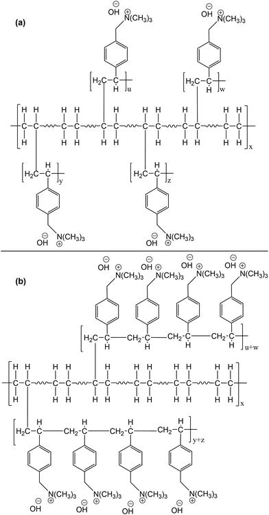
Another important factor that should be considered is the effect of dose rate on the distribution and the length of VBC chains in the grafted polymer. Ideally during simultaneous radiation grafting, each VBC unit should be attached to each of the polyethylene chain upon creation of a free radical leading to very short length graft (Scheme 5a). However, there is a competition between the grafting process and the VBC polymerisation. After the initial VBC unit attached itself to the polyethylene backbone, subsequent VBC units attach to the VBC unit (VBC polymerisation) instead of the polyethylene chain resulting in longer grafts (Scheme 5b). Using higher dose rates will result in faster decay of radicals by recombination and consequently faster termination of the growing VBC chains. This results in a shorter VBC grafted chains due to a decrease in styrene concentration in the internal grafting layers.68,69 While at slow dose rates, VBC diffusion through the base polymer is sufficiently fast and the lifetime of the radicals formed is long enough to result in longer and fewer VBC chain grafts70i.e. faster dose rates will result in better distributed VBC throughout the grafted polymer and more LDPE–VBC links and shorter VBC–VBC links for a given DOG (Scheme 5a).
There seems to be also an effect of the base polymer on the stability of the grafted AEM. While this effect is minimal compared to the dose rate effect, it is still significant. At similar grafting conditions (dose rate, DOG, etc.), the LDPE-based AEM showed 25% slower degradation rate compared to that of HDPE across the studied dose rates. This might arise from the differences in the structural change, e.g. cross-linking, that the base polymer is undergoing under radiation. Since crosslinking takes place between carbon atoms in neighbouring chains or chain branches joining together with other branches of the chain, a highly branched polymer like LDPE is more amenable to crosslinking compared to linear polymer like HDPE.71 It has been shown that under our radiation dose (maximum of 20 kGy for LDPE/HDPE) i.e. below total dose of 100 kGy, LDPE polymer experiences significantly higher cross-linking under radiation than HDPE, with both approaching similar cross-linking values at 250 kGy.72 Additionally, the highly branched LDPE provides more accessible grafting sites in comparison to HDPE (seen by higher DOG for the same grafting conditions) which could translate to better grafting distribution and consequently shorter grafts.
The large variation in grafting requirements of LDPE/HDPE (10–20 kGy) and that of ETFE (70 kGy) makes direct comparison of degradation rate difficult. In the case of ETFE, membrane fabrication using gamma radiation did not produce high enough graft of VBC monomer.16 ETFE-based membranes were then produced via electron beam radiation grafting since high energy electron beam is capable of providing higher dose rate. At a dose rate of 400 Gy h−1, ETFE-based AEM (ET-1 and ET-2) showed IEC loss of 13–15% somewhere in the middle range of IEC loss of LDPE of 21% for 67 Gy h−1 (LT-4) and 11% for 2000 Gy h−1 (LT-1).
4.3 Effect of functional head group
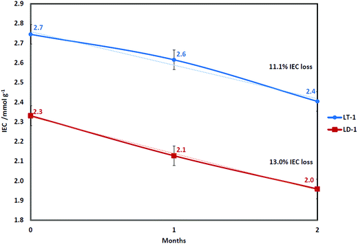
Fig. 1 shows a comparison in IEC drop between TMA- (LT-1) and DABCO-functionalised (LD-1) membranes both having the same DOG of 65% (2000 Gy h−1). The LT-1 membrane exhibited higher initial IEC than the mono-quaternised LD-1 membrane (as shown later by NMR data) since TMA can more effectively penetrate the LDPE-g-VBC copolymer compared to DABCO due to the bulkier structure of DABCO. The lower IEC with the use of DABCO is still acceptable, provided that the resulting membrane is more chemically and thermally stable.73The degradation rates for both membranes were very similar, with IEC loss of 13.0% for DABCO in comparison to 11.1% for TMA. These results were obtained under neutral pH (deionised water) and not in highly alkaline media, where the hydroxide counter ions associated with the head group might not be able to start the nucleophilic attack leading to head group loss under Scheme 1 but rather could undergo ylide formation reaction (Scheme 2). It can be seen that the degradation rate in our tests was less dependent on the head group in comparison to the accelerated tests on the head groups alone in high temperature and alkaline concentration (2 M KOH at 160 °C) which showed much better stability of DABCO than TMA with half-time disintegration of 42 and 29 min, respectively.40 It also suggests that the degradation mechanism under low alkaline concentration and relatively low temperature of 60 °C might be different from the mechanisms reported under accelerated testing using high alkaline concentrations and temperature using single monomer unit.
4.4 Effect of the temperature and degradation time on the membrane stability
The effect of temperature on the degradation rate was studied where representative samples of AEM with varying base polymers (LDPE and HDPE, 35 Gy h−1 and ETFE, 400 Gy h−1; Table 2) were subjected to stability tests employing the same procedure but with increasing temperature and time (Table 3). There was a negligible decrease in IEC at low temperatures of 20 and 40 °C after a 1 month period indicating that the AEMs are stable at temperatures up to 40 °C. At 60 °C, a measurable decrease of IEC was recorded after a 1 month period as discussed earlier.| Membrane | Initial IEC (mmol g−1) | IEC month 1 (mmol g−1) | IEC month 2 (mmol g−1) | ||
|---|---|---|---|---|---|
| 20 °C | 40 °C | 60 °C | 60 °C | ||
| LT-3 | 2.4 ± 0.2 | 2.3 ± 0.1 | 2.2 ± 0.1 | 2.0 ± 0.1 | 1.6 ± 0.1 |
| HT-2 | 2.6 ± 0.2 | 2.5 ± 0.2 | 2.5 ± 0.2 | 2.4 ± 0.2 | 1.4 ± 0.1 |
| ET-2 | 1.5 ± 0.1 | 1.5 ± 0.1 | 1.5 ± 0.1 | 1.4 ± 0.1 | 1.3 ± 0.1 |
4.5 Ionic conductivity of the initial and aged membranes
IEC is a measure of the concentration of the functional groups present to transfer the hydroxide ions and a higher IEC consequently results in a higher ionic conductivity. Loss of functional groups due to membrane's degradation results in lowering its IEC and decrease its measured ionic conductivity.Table 4 shows the through-plane ionic conductivity at 60 °C of HDPE-based membranes, HT-2 and HT-3. Degradation tests on the membranes after 2 months revealed a decrease in ionic conductivity of the membrane (60 °C) by 37.0% (84 to 53 mS cm−1) and 24.7% (101 to 76 mS cm−1). Similarly, LDPE-based membranes showed a decrease in ionic conductivity (60 °C) of 19.0% (84 to 68 mS cm−1) and 14.1% (99 to 85 mS cm−1) for LT-4 and LT-1 membranes, respectively. The decrease in ionic conductivity agrees well with the observed decrease in IEC reported in Table 2 and confirms the earlier conclusion that membranes prepared under high radiation dose rate demonstrates slower degradation compared to using low dose rate. Furthermore, it also confirms that the degradation rate using LDPE-based AEM is slower compared to that of HDPE-based AEM using the same grafting conditions.
| Membrane | Radiation dose rate (Gy h−1) | Functionality | Ionic conductivity (mS cm−1) | |
|---|---|---|---|---|
| Initial | After 2 months | |||
| HT-2 | 35 | TMA | 84 ± 4 | 53 ± 3 |
| HT-3 | 67 | 101 ± 5 | 76 ± 4 | |
| LT-4 | 67 | TMA | 84 ± 4 | 68 ± 3 |
| LT-1 | 2000 | 99 ± 5 | 85 ± 4 | |
| LD-1 | 2000 | DABCO | 69 ± 3 | 52 ± 3 |
The LT-1 membrane showed lower decrease in ionic conductivity at 60 °C after 2 months of 14.1% compared to LD-1 membrane, which showed a decrease of 24.6% (using the same radiation dose rate of 2000 Gy h−1). While both AEMs using TMA and DABCO showed the same % IEC loss after 2 months, the bulkier structure of DABCO and its lower basicity (pKa = 8.72) compared to TMA (pKa = 9.81) results in lower conductivity at similar DOG and IEC. This translates to a larger activation energy of DABCO-based AEM (Ea = 14 kJ mol−1) for OH− ion conductivity and consequently larger effect of IEC decrease on conductivity in comparison to TMA-based AEM (Ea = 12 kJ mol−1).10
4.6 Scanning electron microscopy analysis
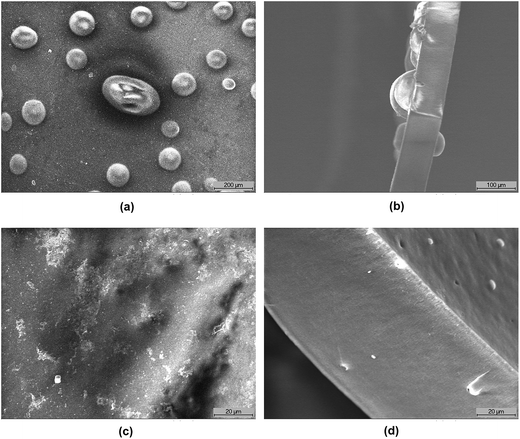
Fig. 2a and b show the scanning electron microscopy (SEM) images of the surface and cross-section, respectively, of the aged LDPE-based membrane prepared under 35 Gy h−1 dose rate (LT-3). The observed voids (bubbles) suggest that part of the polymer was lost and dissolved in the surrounding water during the degradation process leaving the void behind. This is most likely to be the grafted vinylbenzyl groups and not simply the functional head group alone.While polyvinylbenzyl trimethylammonium chloride or hydroxide is water soluble, the grafted LDPE-g-VBC-TMA-OH is not and the potential loss of polymer seen by the SEM must be caused by the degradation mechanism as such degradation/loss was not observed with LDPE-g-VBC-TMA-Cl (from IEC data, Table 1). It also suggests that at such dose rate, the VBC has relatively longer chains and is less distributed throughout the grafted polymer (for a given DOG). Hence, upon scission of the VBC–VBC link, long chains of water soluble vinylbenzyl trimethylammonium hydroxide are lost leaving the large void space observed behind, it was reported74 that at low DOG < 11% bubbles on the membrane surface was observed after grafting and functionalisation due to the strong imbalance between hydrophobic bulk film and the hydrophilic functionalised layer and the bubbles disappeared at DOG levels above 10%. However, this reported imbalance is inapplicable in this study, the investigated LT-3 and LT-1 AEMs have DOG significantly higher than 10%, namely 58% and 65%, respectively. Moreover, the initial functionalised membranes did not show formation of bubbles. Furthermore, the presence of bubbles were only observed after prolonged degradation test (Fig. 2a and b) and are associated with the loss of IEC.
The image of the cross-section of the aged membrane seems to suggest that the degradation starts on the surface then progresses through the membrane. Fig. 2c and d show the surface and cross-sectional structure, respectively, of the aged LDPE-based AEM prepared under higher radiation dose rate of 2000 Gy h−1 (LT-1). SEM micrographs were taken at higher magnification (1000×) and the membranes were still visibly smooth and lacked any bubbles. This supports the earlier results concluding that mutual radiation grafting performed under high dose rate produces more stable AEMs compared to applying low radiation dose rate and suggests that the loss of VBC is more uniform in the structure. This can be explained by better distribution of VBC in the grafted polymer with shorter grafted chains and higher cross-linking resulting in less water soluble by-products. This will be discussed further using various chemical analysis techniques.
4.7 NMR spectroscopy analysis
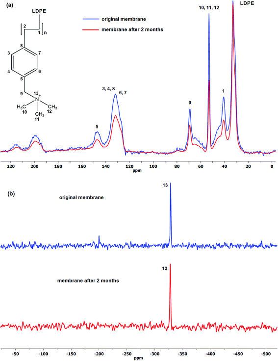
Comparison of the spectra of the initial and aged membranes revealed a decrease in the intensity ratio of the benzyl group to that of LDPE, which indicates decrease in the amount of the particular group in the membrane structure.75 Furthermore, no new signals were detected in both 13C and 15N CP-MAS NMR spectra suggesting no degradation by-products has formed on the membrane itself, the degradation products therefore are water soluble and can be identified in the solution.
Fig. 3a shows the 13C CP-MAS NMR spectra of the initial and aged LT-4 membrane. The aromatic ring carbons (benzyl groups) give the resonance between 125 and 150 ppm. The signals between 190 and 220 ppm and the smaller broad signal between 55 and 85 ppm are spinning sidebands associated to the aromatic carbons. The CH–CH2 groups resonate at 40–50 ppm, N(CH3)3 at 53 ppm and LDPE aliphatic carbons around 20 to 35 ppm. The 69 ppm resonance is assigned to the –CH2N.76–78
It is clear from the spectra that there are losses in the VBC and ammonium (TMA) group peak size. The results show 1![[thin space (1/6-em)]](https://www.rsc.org/images/entities/char_2009.gif) :
:![[thin space (1/6-em)]](https://www.rsc.org/images/entities/char_2009.gif) 1 ratio of VBC to TMA loss wherein the percentage of the loss to their initial values after 2 months degradation was ca. 30%. This agrees well with the observed loss of IEC of ca. 22% and indicates that the majority of the degradation is caused by the loss of the whole vinylbenzyl trimethylammonium hydroxide and not simply just the TMA head group. This is significant since all the proposed mechanisms in the literature involve loss of only the head group (TMA) and not the VBC groups. It was further observed that the ratio of VBC to TMA loss remained close to 1 using high radiation dose rate (2000 Gy h−1, 66% DOG).
1 ratio of VBC to TMA loss wherein the percentage of the loss to their initial values after 2 months degradation was ca. 30%. This agrees well with the observed loss of IEC of ca. 22% and indicates that the majority of the degradation is caused by the loss of the whole vinylbenzyl trimethylammonium hydroxide and not simply just the TMA head group. This is significant since all the proposed mechanisms in the literature involve loss of only the head group (TMA) and not the VBC groups. It was further observed that the ratio of VBC to TMA loss remained close to 1 using high radiation dose rate (2000 Gy h−1, 66% DOG).
Fig. 3b on the other hand, shows the 15N CP-MAS NMR spectra of the same LT-4 AEM. The same quaternised nitrogen peak of TMA at −330 ppm79 can be seen and no other resonance peaks were observed after degradation suggesting that no other nitrogen-containing by-products have formed on the membrane.
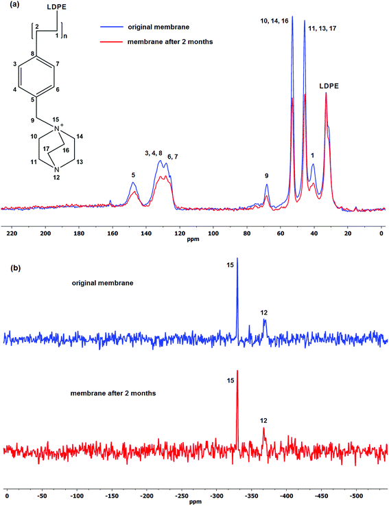
Similarly for the DABCO-functionalised membrane (LD-1), the 13C CP-MAS NMR spectra shown in Fig. 4a share common peaks with that of TMA-based AEM namely, the aliphatic carbon peaks of LDPE at 20 to 35 ppm and the aromatic carbons between 120 to 150 ppm. Total Suppression of Spinning Sidebands (TOSS) was employed during analysis in order to minimise the impact of the spinning sidebands. There are two strong peaks at 46 and 53 ppm representing the carbons attached to the unquaternised and quaternised nitrogen, respectively.80 It can be seen that the sizes of both of those peaks are very similar suggesting equal amounts of unquaternised and quaternised nitrogen, i.e. mono-substituted DABCO which is supposed to offer better stability over double substitution.40 After 2 months degradation period, there is a marked decrease in the peak intensity at 40 ppm indicating loss of VBC, similar to what was observed with the LT-4 membrane (Fig. 3a). However, unlike the aged LT-4 membrane, the results indicate VBC to DABCO loss of 1![[thin space (1/6-em)]](https://www.rsc.org/images/entities/char_2009.gif) :
:![[thin space (1/6-em)]](https://www.rsc.org/images/entities/char_2009.gif) 2 ratio with loss to its initial values of ca. 15% which is in agreement with the observed IEC loss of 13% (Fig. 1).
2 ratio with loss to its initial values of ca. 15% which is in agreement with the observed IEC loss of 13% (Fig. 1).
The resonance peak at −330 ppm in the 15N CP-MAS NMR spectra shown in Fig. 4b is consistent with the quaternised nitrogen in the DABCO structure and the peak at −368 ppm can be associated with the unquaternised nitrogen, both present in the original and degraded membrane.81 Furthermore, no other additional resonance peaks were observed. Unfortunately, the peaks in 15N CP-MAS NMR spectra cannot be integrated to quantify the relative loss of DABCO-nitrogen in both original and degraded membranes.
Nuclear magnetic resonance (NMR) has been the most commonly established method of analysing and monitoring degradation of ionomer membranes.54,82,83 In order to shed more light on the role of OH− ion and oxygen on the degradation process, both solid-state and solution 17O NMR spectroscopy were utilised in order to determine the presence of possible oxygen-containing compounds which could help elucidate the AEM degradation reactions.84 The 17O DE-MAS NMR spectra of the aged LT-1 membrane revealed clear identifiable peaks even with a moderate signal-to-noise ratio that suggests oxidation of the aged membrane as shown in Fig. 5a. Similarly, the water–17O solution wherein the isotope-labelled LT-1 membrane had undergone degradation, was subjected to 17O solution-NMR (Fig. 5b). As expected, the spectra of the solution appear to show predominantly oxygen from H217O solvent and alkaline 17OH− ion,85 but also show other peaks indicating the presence of degradation products.
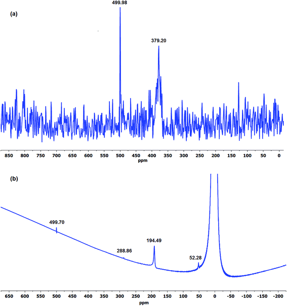 | ||
| Fig. 5 The 17O (a) DE-MAS NMR spectra of aged LT-1 membrane and (b) solution-NMR spectra of the degradation solution after stability test. | ||
Experimental data obtained at 120 °C employing Ag2O-mediated ion exchange reaction have verified mechanism (Scheme 1) indicating formation of a benzylic alcohol and release of TMA as predominant degradation products.50 However, the presence of a benzylic alcohol cannot be ascertained from the 17O NMR spectra (Fig. 5) since its expected chemical shift (0.7 ppm)86 is masked by the predominant oxygen resonance of H217O and 17OH. This can also be due to the possible conversion of benzylic alcohol to dibenzylic ether.57 Furthermore, the peak at 379 ppm (Fig. 5a) suggests presence of carbonyl-containing (C![[double bond, length as m-dash]](https://www.rsc.org/images/entities/char_e001.gif) O) compounds87,88 indicating that the benzylic alcohol, if present, is not the final form of the degradation product, but rather could have undergone subsequent oxidation reactions. Considering that the membrane was subjected to a degradation period of 2 months at 60 °C, the benzylic alcohol by-product may have undergone auto-oxidation to produce aromatic aldehydes and/or other carbonyl compounds.89 Aromatic aldehydes can readily transform to the corresponding carboxylic acid and/or benzylic peroxide radicals.90 This benzylic peroxide radical could lead to a variety of side reactions, which may cause release of benzyl-TMA group from the membrane. The benzylic peroxide radical could have also been responsible for the oxidation of TMA indicated by the presence of N-oxide (N–O) groups (resonance at 500 ppm)88 detected on the aged membrane (Fig. 5a) and in the degradation solution (Fig. 5b). In addition, the broad resonance at around 170 ppm in the 13C CP-MAS spectra (Fig. 6) and the FTIR signals at 1057 (
O) compounds87,88 indicating that the benzylic alcohol, if present, is not the final form of the degradation product, but rather could have undergone subsequent oxidation reactions. Considering that the membrane was subjected to a degradation period of 2 months at 60 °C, the benzylic alcohol by-product may have undergone auto-oxidation to produce aromatic aldehydes and/or other carbonyl compounds.89 Aromatic aldehydes can readily transform to the corresponding carboxylic acid and/or benzylic peroxide radicals.90 This benzylic peroxide radical could lead to a variety of side reactions, which may cause release of benzyl-TMA group from the membrane. The benzylic peroxide radical could have also been responsible for the oxidation of TMA indicated by the presence of N-oxide (N–O) groups (resonance at 500 ppm)88 detected on the aged membrane (Fig. 5a) and in the degradation solution (Fig. 5b). In addition, the broad resonance at around 170 ppm in the 13C CP-MAS spectra (Fig. 6) and the FTIR signals at 1057 ( ) and 1730 (
 ) cm−1 of the degradation products (Fig. 8) provide further evidence of the presence of carbonyl-containing compounds indicating that either both the benzylic alcohol and TMA group might underwent subsequent oxidation and such auto-oxidation reactions could have caused the decrease in IEC of the membrane, or other peroxide radicals could have attacked the VBC–TMA group resulting in the observed carbonyl and N-oxide groups.
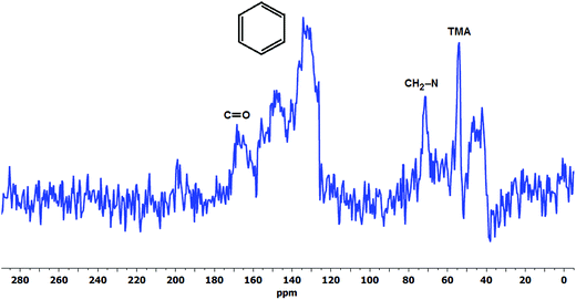 | ||
| Fig. 6 The 13C CP-MAS NMR spectra of the degradation products of LT-1 membrane recovered after drying the degradation solution. | ||
The presence of degradation products in the solution was attributed to the detected resonance peaks as shown in Fig. 5b. The peak at 194 ppm corresponds to peroxides (O–O) and/or soluble carbonate (CO32−) compounds91 present in the solution. There are also common peaks observed in both the solution and solid-state 17O NMR spectra, such as the peak at 500 ppm indicative of oxidised TMA group (N-oxides) and the resonance at 52 ppm (–OH and –O– group)92 suggesting the presence of similar functional groups in both the degradation solution and the aged membrane. However, further studies are required to identify all of the oxygen-containing products observed.
![[thin space (1/6-em)]](https://www.rsc.org/images/entities/char_2009.gif) :
:![[thin space (1/6-em)]](https://www.rsc.org/images/entities/char_2009.gif) 1 ratio of VBC to TMA loss between the original and aged membrane (Fig. 3). Such loss of benzyl-TMA groups can explain the observed decrease in IEC and the large voids seen in SEM (Fig. 2). This is in contrast with typically suggested elimination degradation mechanism which produces only TMA and/or methanol as proposed by-products.19,25 It should be stressed that the later mechanisms are typically suggested in high alkaline media. The broad resonance in the 170 ppm region indicates the presence of carbonyl groups (C
1 ratio of VBC to TMA loss between the original and aged membrane (Fig. 3). Such loss of benzyl-TMA groups can explain the observed decrease in IEC and the large voids seen in SEM (Fig. 2). This is in contrast with typically suggested elimination degradation mechanism which produces only TMA and/or methanol as proposed by-products.19,25 It should be stressed that the later mechanisms are typically suggested in high alkaline media. The broad resonance in the 170 ppm region indicates the presence of carbonyl groups (C![[double bond, length as m-dash]](https://www.rsc.org/images/entities/char_e001.gif) O) suggesting formation of oxidative degradation products discussed earlier. Unfortunately, an attempt to obtain a 15N CP-MAS NMR spectra for the degradation product of the LT-1 membrane was unsuccessful due to low absolute intensity of the carbon spectrum.
O) suggesting formation of oxidative degradation products discussed earlier. Unfortunately, an attempt to obtain a 15N CP-MAS NMR spectra for the degradation product of the LT-1 membrane was unsuccessful due to low absolute intensity of the carbon spectrum.
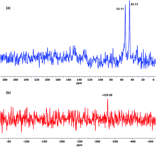 | ||
| Fig. 7 The (a) 13C and (b) 15N CP-MAS NMR spectra of the degradation products of LD-1 membrane after stability test. | ||
Unlike TMA, some of the DABCO upon detachment from the membrane was observed to recrystallise from the solution upon cooling to room temperature. DABCO was subsequently separated by centrifuge and was present predominantly in mono-quaternised form as indicated by the two strong carbon peaks at 45 and 53 ppm as shown in Fig. 7a. Furthermore, the resonance at −330 ppm attributed to quaternised nitrogen in the 15N CP-MAS NMR spectra (Fig. 7b) suggests the detachment of benzyl trimethylammonium groups. The intense resonance of DABCO indicates its presence in excess than VBC in the degradation product which is in agreement with the 1![[thin space (1/6-em)]](https://www.rsc.org/images/entities/char_2009.gif) :
:![[thin space (1/6-em)]](https://www.rsc.org/images/entities/char_2009.gif) 2 ratio of VBC to DABCO loss as observed in Fig. 4a. Since the prepared LD-1 AEM is largely mono-quaternised (weak −368 ppm resonance, Fig. 4b), the unquaternised nitrogen is expectedly too weak to be detected in the degradation products (Fig. 7b).
2 ratio of VBC to DABCO loss as observed in Fig. 4a. Since the prepared LD-1 AEM is largely mono-quaternised (weak −368 ppm resonance, Fig. 4b), the unquaternised nitrogen is expectedly too weak to be detected in the degradation products (Fig. 7b).
4.8 FTIR analysis of the solid degradation products
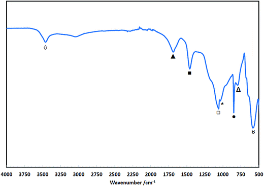
Fig. 8 shows the FTIR spectra of the degradation products (residue isolated from the solution) of TMA-functionalised membrane having different base polymers. It was very evident in all spectra of the degradation products (deg prdt) that there were no detectable strong peaks between the 2800 and 3000 cm−1 region. The 2850 (‡) and 2920 (†) cm−1 peaks in the spectra of the initial membranes are attributed to the –CH2 symmetric and asymmetric stretching, respectively, both of which are characteristic peaks of the ETFE (ET-2), LDPE (LT-1) and HDPE (HT-3).93–95 Additionally for the ET-2 degradation product, there is a clear absence of intense peaks between 1000 and 1300 cm−1 (§) region that can be associated with C–F stretching vibrations.96,97 This agrees with the NMR analysis (Fig. 6) wherein the absence of these characteristic peaks indicates that the base polymers were thermally stable and did not degrade as they were not detected in the degradation products.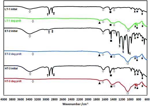 | ||
| Fig. 8 FTIR spectra of the initial TMA-functionalised membranes and the degradation products (deg prdt) with different polymer backbones. | ||
Fig. 8 clearly shows that the spectra of the degradation products for all the different base polymers are identical. This indicates that same degradation products were recovered after the stability test regardless of the type of polymer backbone used. The precipitate contains VBC groups evinced by bands observed at 840 ( ) and 700 (
 ) cm−1 which are consistent with the meta and/or para benzene ring substitution.98 The presence of TMA is attributed to the C–N stretch at 880 cm−1 (
 ) and the N–CH3 symmetric bending deformation at 1393 cm−1 (
 )99 while the band at 1440 cm−1 (
 ) refers to the –CH2 scissoring vibrations.100 The peak at 1660 cm−1 (
 ) is due to the O–H bending of hydrogen bonded water associated with tetramethylammonium hydroxide (TMAH) hydrate.101 This is different with the weak signal observed between 3300 and 3400 cm−1 (
 ) region that is associated with O–H stretching due to possible presence of residual water and/or OH in the degradation product.
The possible presence of carbonyl-containing compounds in the degradation products is shown by the strong C–O and C![[double bond, length as m-dash]](https://www.rsc.org/images/entities/char_e001.gif) O stretching vibrations at 1057 (
O stretching vibrations at 1057 ( ) and 1730 (
 ) cm−1, respectively.102
The FTIR spectra of the degradation product from the LDPE-based membrane functionalised with DABCO (LD-1) is shown in Fig. 9. Similar to the TMA-functionalised membrane (Fig. 8), there is no detected presence of LDPE base polymer in the degradation products as there were no strong peaks observed between the 2800 and 3000 cm−1 region, which also confirms with the NMR analysis (Fig. 7). The peaks observed at 1700 ( ), 1057 (
 ) and 583 cm−1 (
 ) suggest existence of carbonyl-containing (aldehyde and/or ketone) by-products, while the bands at 848 (
 ) and 796 cm−1 (
 ) are attributed to the meta and/or para substitutions of the VBC98 indicating presence of aromatic compounds in the degradation product. The presence of DABCO in the degradation product was confirmed by the bending deformation at 1460 cm−1 (
 ) of the CH2 groups103 while the strong signal at 1030 cm−1 (
 ) is due to C–N stretching vibrations in the DABCO structure.104,105
4.9 Mechanism of AEM degradation
Studies on the mechanisms of degradation and measurements of the degradation rates of fabricated membranes reported in the literature were all performed in media with high alkaline concentration and temperature. The degradation rates reported therein are driven predominantly by the loss of head group due to very high alkaline concentration (OH− ion attack) at elevated temperature (Scheme 1). However, such test conditions are actually very far from the real operating environments of low-temperature fuel cells and electrolysers (i.e. close to neutral medium). As previously discussed, AEM degradation due to IEC loss was observed even at very low alkaline concentration (deionised water) at temperature of 60 °C. Results suggest that not only the loss of TMA head group and VBC monomer were responsible for the loss of IEC but also parallel oxidation processes are likely taking place that provide other routes to degradation. Therefore, in actual fuel cell and electrolyser systems that use water media with very low alkalinity and constantly exposed to oxygen gas, the investigation of membrane degradation should shift to the effect of varying the oxygen concentration rather than simply the OH− ion concentration on stability. Consequently, this suggests that the rate of membrane degradation due to auto-oxidation can have a significant impact aside from the established degradation mechanisms due to loss of head group.The decrease in ionic conductivity brought about by the decrease in IEC due to the degradation of the fabricated membrane is more pronounced under 100% humidified stream of oxygen than nitrogen at 80 °C as we have reported previously.41 The degradation rate in terms of ionic conductivity is 4 times faster in oxygen than in nitrogen which suggests that at very low alkaline concentration, such four-fold increase in degradation rate indicates another degradation mechanism taking place alongside (i.e. oxidation) or at very low alkaline concentration with negligible head group loss (Scheme 1) one mechanism that is accelerated by oxygen concentration.
The observed ca. 5.5% loss after 1 month in air-saturated deionised water at 60 °C (Fig. 1, LT-1) was compared with reported degradation rates in literature. Einsla et al.55 observed a 10% loss of benzyltrimethylammonium (BTMA) cation (compound) at 80 °C after 1 month under 1 M alkaline and nitrogen atmosphere. There was no change in degradation rate in the studied alkaline concentration range between 1–5 M. Using the reported activation energy (15.8 kcal mol−1), the degradation rate at 60 °C of the same BTMA cation was estimated to be 2.6% after 1 month in 1 M KOH. This is less than half of the % loss after 1 month in air-saturated deionised water we obtained of 5.5% with the highest radiation dose and an order of magnitude lower than the lowest dose rate (25%) indicating that the degradation of the fabricated membranes investigated is not only due to the removal of the head group but could also due to other mechanisms involving oxygen.
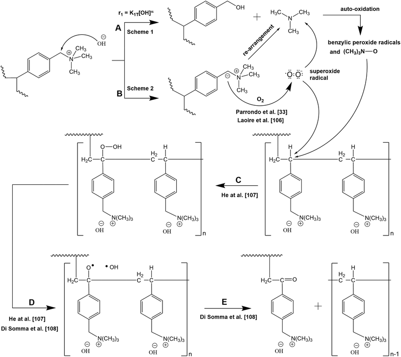
We therefore suggest an alternative degradation mechanism for AEMs immersed in close to neutral pH solutions (deionised water) that involves oxidation of the initial degradation products and the ylide intermediate (Scheme 6) which can explain the above observations. A parallel observation that suggests peroxide radicals could be generated from ylide (Scheme 2) was recently reported33 employing 31P NMR spectroscopy and using polyphenylene oxide (PPO) as base polymer for the TMA-based AEM. It was reported that auto-oxidation is favoured under alkaline conditions and the degradation of AEM was due to hydroxyl and superoxide anion radicals formation which were found to be responsible for the PPO backbone chain scission.
 | ||
| Scheme 6 Proposed degradation pathways for TMA-functionalised AEM in media with very low alkaline concentration. | ||
In the proposed mechanism (Scheme 6), the degradation of the membrane is governed by 2 reaction routes (A and B) which can proceed simultaneously. Initially, in alkaline environment, AEM degradation proceeds with the loss of the head group (Scheme 1) as widely reported, hereby indicated as Reaction A. The reaction rate (r1) in terms of loss of head group is a function of the OH− ion concentration and operating temperature, wherein subjecting the membrane to highly alkaline media and temperature expect a high degradation rate via head group loss. The initial degradation products of Reaction A could subsequently undergo auto-oxidation/oxidation to form benzylic peroxide radicals and TMA-oxide radicals. The reaction rate in terms of auto-oxidation reaction is dependent on temperature and on degradation products and oxygen concentrations, wherein as more oxygen is fed to the system at constant alkaline concentration and temperature, more N-oxide and peroxide radicals will be created. These benzylic peroxide radicals and TMA-oxide radicals could possibly attack the benzylic carbon liberating VBC–TMA causing further decrease in IEC of the AEM depending on the length of the VBC grafts, n. However, we observed 1![[thin space (1/6-em)]](https://www.rsc.org/images/entities/char_2009.gif) :
:![[thin space (1/6-em)]](https://www.rsc.org/images/entities/char_2009.gif) 1 ratio of VBC to TMA loss of prepared LT-4 AEM (Fig. 3), suggesting that at very low alkaline concentration, the loss of head group due to OH− ion attack (Reaction A) has minor contribution to membrane degradation and is rather mainly attributed to the loss of VBC–TMA group as a whole (Reaction B).
1 ratio of VBC to TMA loss of prepared LT-4 AEM (Fig. 3), suggesting that at very low alkaline concentration, the loss of head group due to OH− ion attack (Reaction A) has minor contribution to membrane degradation and is rather mainly attributed to the loss of VBC–TMA group as a whole (Reaction B).
The degradation route via Reaction A can be applicable to DABCO-based AEM (LD-1) where a 1![[thin space (1/6-em)]](https://www.rsc.org/images/entities/char_2009.gif) :
:![[thin space (1/6-em)]](https://www.rsc.org/images/entities/char_2009.gif) 2 ratio of VBC to DABCO loss was observed (Fig. 4) indicating better stability of TMA than DABCO even at same radiation dose rate due to more loss of DABCO head group than VBC. This suggests that the degradation of LD-1 membrane is not solely due to removal of the whole VBC–DABCO group but could also involve the auto-oxidation of the initial degradation products of the nucleophilic substitution reaction (i.e. membrane degradation proceeds through both Reaction A and B). Therefore, this indicates that at very low alkaline concentration, the ratio of VBC to head group loss dictates the relative yields of degradation routes and that different head group types could follow one or more degradation pathways depending on the applied radiation dose rate.
2 ratio of VBC to DABCO loss was observed (Fig. 4) indicating better stability of TMA than DABCO even at same radiation dose rate due to more loss of DABCO head group than VBC. This suggests that the degradation of LD-1 membrane is not solely due to removal of the whole VBC–DABCO group but could also involve the auto-oxidation of the initial degradation products of the nucleophilic substitution reaction (i.e. membrane degradation proceeds through both Reaction A and B). Therefore, this indicates that at very low alkaline concentration, the ratio of VBC to head group loss dictates the relative yields of degradation routes and that different head group types could follow one or more degradation pathways depending on the applied radiation dose rate.
Reaction B proceeds as proposed by Parrondo et al.33 wherein the carbanion reduces the dissolved oxygen present in the solution to produce superoxide radicals. Such process involves one-electron reduction of the dissolved oxygen leading to the formation of O2/O2− (superoxide) redox couple.106 The ylide formation and consequently the superoxide explain why degradation in terms of IEC loss is not due to direct oxygen reaction with VBC–TMA as IEC loss was only observed when the membranes were in the OH− form and was not observed in Cl− form (Table 1). The presence of carbonyl-containing compounds and N-oxide groups (Fig. 5) also support the hypothesis of the formation of these superoxides. Consequently, in the absence of high OH− ion concentration in the surrounding media, these superoxide radicals can attack the vulnerable benzylic carbon of the LDPE–VBC resulting in the release of VBC–TMA groups.
The attack of free radicals (benzylic peroxide, TMA-oxide, or superoxide radicals) on the vulnerable carbon (carbon in para position with respect to the trimethyl ammonium hydroxide group) gives rise to the formation of a hydroperoxide moiety (Reaction C) reported for cumene.107 The hydroperoxide group is expectedly unstable and is easily fragmented to hydroxyl and oxide radicals upon thermal decomposition (Reaction D),107,108 which subsequently rearranges to form ketone (C![[double bond, length as m-dash]](https://www.rsc.org/images/entities/char_e001.gif) O) by-product and cause the detachment of VBC–TMA chains.108
O) by-product and cause the detachment of VBC–TMA chains.108
The reaction rate in terms of free radical attack is influenced by the applied radiation dose rate. Therefore, at a fixed operating temperature with constant OH− ion and oxygen concentration, the degradation rate is solely dependent on the applied radiation dose rate during AEM synthesis. Membranes prepared under low radiation dose rate produce longer VBC–VBC chains (high value of n) resulting in higher IEC loss upon chain scission of the long VBC grafts. As observed in the SEM image (Fig. 2), the even distribution of bubbles (voids) suggests long VBC–VBC grafts as few active sites for LDPE–VBC were created due to low applied radiation dose rate. On the other hand, membranes prepared under high radiation dose rate will have more uniform VBC monomer distribution producing more LDPE–VBC grafts and shorter VBC–VBC links (low value of n), hence slower degradation due to lower IEC loss per attack.
5. Conclusion
The chemical and thermal stability of radiation-grafted anion-exchange membrane (AEM) are important properties that dictate its service life for fuel cell and electrolyser applications. This research has investigated the stability of fabricated AEMs in deionised water which is the usual medium for electrolyser and fuel cell operation. After the stability test, there was an observed decrease in IEC, hence a decrease in ionic conductivity, which is an indication of AEM degradation. The stability of the membrane was found to be influenced by the applied gamma radiation dose rate. The use of higher radiation dose rate produces membranes with enhanced stability due to the improved VBC monomer distribution throughout the grafted monomer, hence more LDPE–VBC grafts and shorter VBC–VBC links. The increase in applied radiation dose rate from 30 to 67 Gy h−1 (total radiation dose of 10 kGy) for the LDPE-based AEM significantly reduced the % IEC loss from 37 to 21%, respectively. The same was observed with HDPE-based AEM where the % IEC loss decreased from 50% to 28% with similar increase in radiation dose rate. The stability of the LDPE-based AEM even further improved when the applied radiation dose rate and total radiation dose were increased to 2000 Gy h−1 and 20 kGy, respectively, with only 11% IEC loss. The ETFE-based AEMs, on the other hand, were fabricated using an electron beam radiation source and at 400 Gy h−1 radiation dose rate demonstrated comparable stability to that of the LDPE based AEM (2000 Gy h−1) having 13–15% IEC loss.The use of different base polymer types among those investigated revealed minimal effect on the stability of the resulting AEM, which is mainly influenced by the structural changes (e.g. cross-linking, chain graft lengths, DOG) during radiation grafting. In terms of functional groups, there was limited effect of the studied head group on IEC% loss, the TMA has emerged to offer slightly better stability than DABCO (under the same radiation dose rate).
NMR (solution and solid-state) and FTIR analyses of both the aged TMA- and DABCO-functionalised membranes and their degradation products confirmed loss of not only the functional group but also the VBC which is in contrast with typically reported degradation mechanisms of AEMs in high alkaline media where degradation is carried out under inert atmosphere using simple BTMA compound instead of polymer membrane. At very low alkaline concentration, the reaction rates of membrane degradation were dependent on both oxygen concentration present in the surrounding media and on the applied radiation dose rate. When the concentration of dissolved oxygen in the solution is increased, the rate of membrane degradation due to IEC loss is also increased, the most likely reason for this is formation of superoxide radicals that attack the vulnerable benzylic carbon and cause the release of VBC–TMA. Moreover, 17O NMR analysis of the aged membrane and the degradation products suggest the presence of carbonyl-containing compounds and N–O compounds indicating that oxidative processes could possibly take place. Either the benzylic alcohol and TMA by-products are not the terminal form of the degradation products and could undergo further auto-oxidation leading to further loss of VBC through benzylic peroxide radicals attack and TMA-oxide radicals attack, or another more probable explanation is that peroxide radicals generated from dissolved oxygen through the ylide formation are responsible for these oxidations and for VBC–TMA loss. This explains the faster degradation rate under oxygen gas feed compared to nitrogen under fuel cell operation reported previously.41
This study therefore recommends that future research on AEM materials and degradation study should be conducted at pH closer to neutral and in oxygen saturated environment. The effort should be on improving AEM stability towards oxidation instead of testing head group stability for E2 or SN2 attack in nitrogen saturated high alkaline environment. Lastly, polymer grafting performed under low radiation dose rate produces long chain grafts that leave large void spaces upon chain scission. Preparation of AEMs with high radiation dose rate resulted in a lower % IEC loss and improved stability explained by shorter grafts length, which the established degradation mechanisms reported in literature have not taken into account.
Acknowledgements
The authors acknowledge the support of the Engineering and Physical Sciences Research Council (EPSRC) for funding under Grant Number EP/M005895/1 and the Philippine Department of Science and Technology through the Engineering Research and Development for Technology Program (ERDT-DOST) for funding Richard Espiritu's PhD fellowship. In compliance with EPSRC rules, data supporting this publication is openly available under an ‘Open Data Commons Open Database License’. The additional metadata are available at http://dx.doi.org/10.17634/138124-1. Please contact Newcastle University Research Data Service at rdm@ncl.ac.uk for access instructions. The authors further express their gratitude to the EPSRC National Solid-state NMR Service at Durham University for the solid-state NMR spectra.References
- L. Carrette, K. A. Friedrich and U. Stimming, ChemPhysChem, 2000, 1, 162–193 CrossRef CAS PubMed.
- M. Mamlouk, K. Scott, J. A. Horsfall and C. Williams, Int. J. Hydrogen Energy, 2011, 36, 7191–7198 CrossRef CAS.
- M. Mamlouk, S. M. S. Kumar, P. Gouerec and K. Scott, J. Power Sources, 2011, 196, 7594–7600 CrossRef CAS.
- M. Mamlouk, X. Wang, K. Scott, J. A. Horsfall and C. Williams, Proc. Inst. Mech. Eng., Part A, 2011, 225, 152–160 CrossRef CAS.
- C. C. Pavel, F. Cecconi, C. Emiliani, S. Santiccioli, A. Scaffidi, S. Catanorchi and M. Comotti, Angew. Chem., Int. Ed., 2014, 53, 1378–1381 CrossRef CAS PubMed.
- J. R. Varcoe and R. C. T. Slade, Fuel Cells, 2005, 5, 187–200 CrossRef CAS.
- Y.-C. Cao, X. Wang and K. Scott, J. Power Sources, 2012, 201, 226–230 CrossRef CAS.
- E. Antolini and E. R. Gonzalez, J. Power Sources, 2010, 195, 3431–3450 CrossRef CAS.
- J. R. Varcoe, M. Beillard, D. M. Halepoto, J. P. Kizewski, S. Poynton and R. C. T. Slade, ECS Trans., 2008, 16, 1819–1834 CAS.
- M. Mamlouk and K. Scott, J. Power Sources, 2012, 211, 140–146 CrossRef CAS.
- T. Zhou, R. Shao, S. Chen, X. He, J. Qiao and J. Zhang, J. Power Sources, 2015, 293, 946–975 CrossRef CAS.
- S. Gu, J. Wang, B. Zhang, R. B. Kaspar and Y. Yan, in Materials for Low-Temperature Fuel Cells, Wiley-VCH Verlag GmbH & Co. KGaA, 2014, pp. 125–144, DOI:10.1002/9783527644308.ch06.
- O. I. Deavin, S. Murphy, A. L. Ong, S. D. Poynton, R. Zeng, H. Herman and J. R. Varcoe, Energy Environ. Sci., 2012, 5, 8584–8597 CAS.
- T. Sata, M. Tsujimoto, T. Yamaguchi and K. Matsusaki, J. Membr. Sci., 1996, 112, 161–170 CrossRef CAS.
- K. Scott, M. Mamlouk, R. Espiritu and X. Wu, ECS Trans., 2013, 58, 1903–1906 CrossRef.
- M. Mamlouk, J. A. Horsfall, C. Williams and K. Scott, Int. J. Hydrogen Energy, 2012, 37, 11912–11920 CrossRef CAS.
- S. Chempath, J. M. Boncella, L. R. Pratt, N. Henson and B. S. Pivovar, J. Phys. Chem. C, 2010, 114, 11977–11983 CAS.
- A. C. Cope and A. S. Mehta, J. Am. Chem. Soc., 1963, 85, 1949–1952 CrossRef CAS.
- J. R. Varcoe, P. Atanassov, D. R. Dekel, A. M. Herring, M. A. Hickner, P. A. Kohl, A. R. Kucernak, W. E. Mustain, K. Nijmeijer, K. Scott, T. Xu and L. Zhuang, Energy Environ. Sci., 2014, 7, 3135–3191 CAS.
- G. Merle, M. Wessling and K. Nijmeijer, J. Membr. Sci., 2011, 377, 1–35 CrossRef CAS.
- J. Cheng, G. He and F. Zhang, Int. J. Hydrogen Energy, 2015, 40, 7348–7360 CrossRef CAS.
- C. Fujimoto, D.-S. Kim, M. Hibbs, D. Wrobleski and Y. S. Kim, J. Membr. Sci., 2012, 423–424, 438–449 CrossRef CAS.
- Y. Yuesheng and A. E. Yossef, in Polymers for Energy Storage and Delivery: Polyelectrolytes for Batteries and Fuel Cells, American Chemical Society, 2012, vol. 1096, ch. 14, pp. 233–251 Search PubMed.
- C. Vogel and J. Meier-Haack, Desalination, 2014, 342, 156–174 CrossRef CAS.
- S. Chempath, B. R. Einsla, L. R. Pratt, C. S. Macomber, J. M. Boncella, J. A. Rau and B. S. Pivovar, J. Phys. Chem. C, 2008, 112, 3179–3182 CAS.
- H. Long, K. Kim and B. S. Pivovar, J. Phys. Chem. C, 2012, 116, 9419–9426 CAS.
- C. G. Arges and V. K. Ramani, ECS Trans., 2013, 50, 2183–2197 CrossRef.
- G. Ghigo, S. Cagnina, A. Maranzana and G. Tonachini, J. Org. Chem., 2010, 75, 3608–3617 CrossRef CAS PubMed.
- Z. Wang, in Comprehensive Organic Name Reactions and Reagents, John Wiley & Sons, Inc., 2010, DOI:10.1002/9780470638859.conrr591.
- G. Couture, A. Alaaeddine, F. Boschet and B. Ameduri, Prog. Polym. Sci., 2011, 36, 1521–1557 CrossRef CAS.
- S. J. Peighambardoust, S. Rowshanzamir and M. Amjadi, Int. J. Hydrogen Energy, 2010, 35, 9349–9384 CrossRef CAS.
- S. A. Nuñez and M. A. Hickner, ACS Macro Lett., 2012, 2, 49–52 CrossRef.
- J. Parrondo, Z. Wang, M.-S. J. Jung and V. Ramani, Phys. Chem. Chem. Phys., 2016, 18, 19705–19712 RSC.
- C. G. Arges and V. Ramani, Proc. Natl. Acad. Sci. U. S. A., 2013, 110, 2490–2495 CrossRef CAS PubMed.
- K. S. Ngai, S. Ramesh, K. Ramesh and J. C. Juan, Ionics, 2016, 22, 1259–1279 CrossRef CAS.
- T. N. Danks, R. C. T. Slade and J. R. Varcoe, J. Mater. Chem., 2002, 12, 3371–3373 RSC.
- Q. Zhang, Q. Zhang, J. Wang, S. Zhang and S. Li, Polymer, 2010, 51, 5407–5416 CrossRef CAS.
- K. Matsui, E. Tobita, K. Sugimoto, K. Kondo, T. Seita and A. Akimoto, J. Appl. Polym. Sci., 1986, 32, 4137–4143 CrossRef CAS.
- S. Gu, R. Cai, T. Luo, Z. Chen, M. Sun, Y. Liu, G. He and Y. Yan, Angew. Chem., Int. Ed., 2009, 48, 6499–6502 CrossRef CAS PubMed.
- B. Bauer, H. Strathmann and F. Effenberger, Desalination, 1990, 79, 125–144 CrossRef CAS.
- R. Espiritu, M. Mamlouk and K. Scott, Int. J. Hydrogen Energy, 2016, 41, 1120–1133 CrossRef CAS.
- Y. Zhang, J. Fang, Y. Wu, H. Xu, X. Chi, W. Li, Y. Yang, G. Yan and Y. Zhuang, J. Colloid Interface Sci., 2012, 381, 59–66 CrossRef CAS PubMed.
- T. A. Sherazi, J. Yong Sohn, Y. Moo Lee and M. D. Guiver, J. Membr. Sci., 2013, 441, 148–157 CrossRef CAS.
- H. Zarrin, J. Wu, M. Fowler and Z. Chen, J. Membr. Sci., 2012, 394–395, 193–201 CrossRef CAS.
- N. Li, M. D. Guiver and W. H. Binder, ChemSusChem, 2013, 6, 1376–1383 CrossRef CAS PubMed.
- K. J. T. Noonan, K. M. Hugar, H. A. Kostalik, E. B. Lobkovsky, H. D. Abruña and G. W. Coates, J. Am. Chem. Soc., 2012, 134, 18161–18164 CrossRef CAS PubMed.
- E. N. Komkova, D. F. Stamatialis, H. Strathmann and M. Wessling, J. Membr. Sci., 2004, 244, 25–34 CrossRef CAS.
- H. Xu, J. Fang, M. Guo, X. Lu, X. Wei and S. Tu, J. Membr. Sci., 2010, 354, 206–211 CrossRef CAS.
- S. Maurya, S.-H. Shin, M.-K. Kim, S.-H. Yun and S.-H. Moon, J. Membr. Sci., 2013, 443, 28–35 CrossRef CAS.
- A. D. Mohanty and C. Bae, J. Mater. Chem. A, 2014, 2, 17314–17320 CAS.
- C. G. Arges and V. Ramani, J. Electrochem. Soc., 2013, 160, F1006–F1021 CrossRef CAS.
- H. W. Zhang, D. Z. Chen, Y. Xianze and S. B. Yin, Fuel Cells, 2015, 15, 761–780 CrossRef CAS.
- J. B. Edson, C. S. Macomber, B. S. Pivovar and J. M. Boncella, J. Membr. Sci., 2012, 399–400, 49–59 CrossRef CAS.
- M. R. Sturgeon, C. S. Macomber, C. Engtrakul, H. Long and B. S. Pivovar, J. Electrochem. Soc., 2015, 162, F366–F372 CrossRef CAS.
- B. R. Einsla, S. Chempath, L. Pratt, J. Boncella, J. Rau, C. Macomber and B. Pivovar, ECS Trans., 2007, 11, 1173–1180 CAS.
- T. S. Stevens, E. M. Creighton, A. B. Gordon and M. MacNicol, J. Chem. Soc., 1928, 3193–3197, 10.1039/JR9280003193.
- W. K. Musker, J. Am. Chem. Soc., 1964, 86, 960–961 CrossRef CAS.
- Z. Yang, J. Ran, B. Wu, L. Wu and T. Xu, Curr. Opin. Chem. Eng., 2016, 12, 22–30 CrossRef.
- S. W. Kantor and C. R. Hauser, J. Am. Chem. Soc., 1951, 73, 4122–4131 CrossRef CAS.
- A. Singh, Radiat. Phys. Chem., 1999, 56, 375–380 CrossRef CAS.
- K. Wündrich, Radiat. Phys. Chem., 1984, 24, 503–510 CrossRef.
- S. S. Cota, V. Vasconcelos, M. Senne Jr, L. L. Carvalho, D. B. Rezende and R. F. Côrrea, Braz. J. Chem. Eng., 2007, 24, 259–265 CAS.
- D. Gheysari, A. Behjat and M. Haji-Saeid, Eur. Polym. J., 2001, 37, 295–302 CrossRef CAS.
- K. Yoko, in Irradiation of Food and Packaging, American Chemical Society, 2004, vol. 875, ch. 16, pp. 262–276 Search PubMed.
- V. J. Krasnansky, B. G. Achhammer and M. S. Parker, Polym. Eng. Sci., 1961, 1, 133–138 CAS.
- D. Plester, in Industrial Sterilization, ed. P. Briggs and W. Miller, Duke University Press, Durham, NC, 1973, pp. 141–152 Search PubMed.
- K. J. Hemmerich, Med. Device Diagn. Ind., 2000, 22, 78–89 Search PubMed.
- H. C. Sutton and J. Rotblat, Nature, 1957, 180, 1332–1333 CrossRef CAS PubMed.
- E. Moura, E. S. R. Somessari, C. G. Silveira, H. A. Paes, C. A. Souza, W. Fernandes, J. E. Manzoli and A. B. C. Geraldo, Radiat. Phys. Chem., 2011, 80, 175–181 CrossRef CAS.
- M. M. Nasef, H. Saidi, A. M. Dessouki and E. M. Ei-Nesr, Polym. Int., 2000, 49, 399–406 CrossRef CAS.
- S. M. Tamboli, S. T. Mhaske and D. D. Kale, Indian J. Chem. Technol., 2004, 11, 853–864 CAS.
- D. Gheysari and A. Behjat, Eur. Polym. J., 2001, 37, 2011–2016 CrossRef CAS.
- M. R. Hibbs, J. Polym. Sci., Part B: Polym. Phys., 2013, 51, 1736–1742 CrossRef CAS.
- B. Gupta, M. Staub, G. G. Scherer and D. Grman, J. Polym. Sci., Part A: Polym. Chem., 1995, 33, 1545–1549 CrossRef CAS.
- J. Mališ, P. Mazúr, M. Paidar, T. Bystron and K. Bouzek, Int. J. Hydrogen Energy, 2016, 41, 2177–2188 CrossRef.
- M. Faraj, M. Boccia, H. Miller, F. Martini, S. Borsacchi, M. Geppi and A. Pucci, Int. J. Hydrogen Energy, 2012, 37, 14992–15002 CrossRef CAS.
- C. Yang, S. Wang, W. Ma, L. Jiang and G. Sun, J. Membr. Sci., 2015, 487, 12–18 CrossRef CAS.
- R. V. Law, D. C. Sherrington, C. E. Snape, I. Ando and H. Korosu, Ind. Eng. Chem. Res., 1995, 34, 2740–2749 CrossRef CAS.
- G. H. Penner, R. Webber and L. A. O'Dell, Can. J. Chem., 2011, 89, 1036–1046 CrossRef CAS.
- T. Takewaki, L. W. Beck and M. E. Davis, Microporous Mesoporous Mater., 1999, 33, 197–207 CrossRef CAS.
- K. K. Laali, A. Jamalian and C. Zhao, Tetrahedron Lett., 2014, 55, 6643–6646 CrossRef CAS.
- L. Ghassemzadeh, M. Marrony, R. Barrera, K. D. Kreuer, J. Maier and K. Müller, J. Power Sources, 2009, 186, 334–338 CrossRef CAS.
- B. Wang, W. Sun, F. Bu, X. Li, H. Na and C. Zhao, Int. J. Hydrogen Energy, 2016, 41, 3102–3112 CrossRef CAS.
- T. M. Alam, M. Celina, R. A. Assink, R. L. Clough and K. T. Gillen, Radiat. Phys. Chem., 2001, 60, 121–127 CrossRef CAS.
- V. Maemets and I. Koppel, J. Chem. Soc., Faraday Trans., 1997, 93, 1539–1542 RSC.
- P. Balakrishnan, A. L. Baumstark and D. W. Boykin, Tetrahedron Lett., 1984, 25, 169–172 CrossRef CAS.
- D. Boykin, 17O NMR Spectroscopy in Organic Chemistry, CRC Press, USA, 1990 Search PubMed.
- I. P. Gerothanassis, Prog. Nucl. Magn. Reson. Spectrosc., 2010, 56, 95–197 CrossRef CAS PubMed.
- X. Wang and D. Z. Wang, Tetrahedron, 2011, 67, 3406–3411 CrossRef CAS.
- M. Sankar, E. Nowicka, E. Carter, D. M. Murphy, D. W. Knight, D. Bethell and G. J. Hutchings, Nat. Commun., 2014, 5, 1–6 Search PubMed.
- W. G. Klemperer, Angew. Chem., Int. Ed. Engl., 1978, 17, 246–254 CrossRef.
- J.-P. Kintzinger, in Oxygen-17 and Silicon-29, Springer Berlin Heidelberg, Berlin, Heidelberg, 1981, pp. 1–64, DOI:10.1007/978-3-642-87762-9_1.
- J. V. Gulmine, P. R. Janissek, H. M. Heise and L. Akcelrud, Polym. Test., 2002, 21, 557–563 CrossRef CAS.
- G. Socrates, Infrared Characteristic Group Frequencies: Tables and Charts, John Wiley & Sons, England, 2nd edn, 1994 Search PubMed.
- M. M. Nasef, H. Saidi and K. Z. M. Dahlan, Radiat. Phys. Chem., 2003, 68, 875–883 CrossRef CAS.
- Y. Zhao, H. Yu, D. Xing, W. Lu, Z. Shao and B. Yi, J. Membr. Sci., 2012, 421–422, 311–317 CrossRef CAS.
- J. Fang, Y. Yang, X. Lu, M. Ye, W. Li and Y. Zhang, Int. J. Hydrogen Energy, 2012, 37, 594–602 CrossRef CAS.
- H. Liu, S. Yang, S. Wang, J. Fang, L. Jiang and G. Sun, J. Membr. Sci., 2011, 369, 277–283 CrossRef CAS.
- R. B. Viana, A. B. F. da Silva and A. S. Pimentel, Adv. Phys. Chem., 2012, 2012, 14 Search PubMed.
- N. V. Venkataraman and S. Vasudevan, J. Phys. Chem. B, 2001, 105, 1805–1812 CrossRef CAS.
- K. M. Harmon and I. Gennick, Inorg. Chem., 1975, 14, 1840–1845 CrossRef CAS.
- N. G. Sahoo, H. Bao, Y. Pan, M. Pal, M. Kakran, H. K. F. Cheng, L. Li and L. P. Tan, Chem. Commun., 2011, 47, 5235–5237 RSC.
- A. Hasaninejad, M. Shekouhy, N. Golzar, A. Zare and M. M. Doroodmand, Appl. Catal., A, 2011, 402, 11–22 CrossRef CAS.
- A. Filpi, M. Boccia, A. Pucci and F. Ciardelli, e-Polym., 2013, 13, 1–14 CrossRef CAS.
- V. I. Kovalenko, A. A. Akhmadiyarov, A. E. Vandyukov and A. R. Khamatgalimov, J. Mol. Struct., 2012, 1028, 134–140 CrossRef CAS.
- C. O. Laoire, S. Mukerjee, K. M. Abraham, E. J. Plichta and M. A. Hendrickson, J. Phys. Chem. C, 2009, 113, 20127–20134 CAS.
- Y.-F. He, R.-M. Wang, Y.-Y. Liu, Y. Chang, Y.-P. Wang, C.-G. Xia and J.-S. Suo, J. Mol. Catal. A: Chem., 2000, 159, 109–113 CrossRef CAS.
- I. Di Somma, R. Andreozzi, M. Canterino, V. Caprio and R. Sanchirico, AIChE J., 2008, 54, 1579–1584 CrossRef CAS.
| This journal is © The Royal Society of Chemistry 2017 |

