3D graphene framework supported Li2S coated with ultra-thin Al2O3 films: binder-free cathodes for high-performance lithium sulfur batteries†
Yan
Chen‡
a,
Songtao
Lu‡
a,
Jia
Zhou
a,
Xiaohong
Wu
 *a,
Wei
Qin
 *b,
Ogechi
Ogoke
c and
Gang
Wu
*c
aSchool of Chemistry and Chemical Engineering, Harbin Institute of Technology, Harbin, 150001, PR China. E-mail: wuxiaohong@hit.edu.cn; Fax: +86 451 86402522; Tel: +86 451 86402522
bSchool of Materials Science and Engineering, Harbin Institute of Technique, Harbin 150001, China. E-mail: qinwei@hit.edu.cn
cDepartment of Chemical and Biological Engineering, University at Buffalo, The State University of New York, Buffalo, NY 14260, USA. E-mail: gangwu@buffalo.edu
First published on 11th October 2016
Abstract
Lithium sulfide (Li2S) has drawn special attention as a promising cathode material for emerging energy storage systems due to its high theoretical specific capacity and great compatibility with lithium metal-free anodes. However, Li2S cathodes urgently require a solution to increase their poor electrical conductivity and to suppress the dissolution of long-chain polysulfide (Li2Sn, 4 ≤ n ≤ 8) species into electrolyte. To this end, we report a free-standing Al2O3–Li2S–graphene oxide sponge (GS) composite cathode, in which ultrathin Al2O3 films are preferentially coated on Li2S by an atomic layer deposition (ALD) technique. As a result, a combination of high electron conductivity (from GS) and strong binding with Li2Sn (from ultrathin Al2O3 films) was designed for cathodes. The newly developed Al2O3–Li2S–GS cathodes are able to deliver a highly reversible capacity of 736 mA h gLi2S−1 (427 mA h gcathode−1) at 0.2C, which is much higher than that of corresponding cathodes without Al2O3 (59%). Also, the long-term cycling stability of Al2O3–Li2S–GS cathodes was demonstrated up to 300 cycles at 0.5C with an excellent capacity retention of 88%. In addition, combined with density functional theory calculations, the promotional mechanism of ultrathin Al2O3 films was elucidated using extensive characterization. The ultra-thin Al2O3 film with optimal thickness not only acts as a physical barrier to Li2S nanoparticles, but provides a strong binding interaction to suppress Li2Sn species dissolution.
Introduction
The rapid development of portable and flexible electronic devices creates an increasing demand for an energy storage system with larger energy density, improved safety and lighter weight.1,2 Rechargeable lithium/sulfur (Li/S) batteries are considered one of the most promising candidates due to their high theoretical energy density of 2580 W h kg−1 and specific capacity of 1672 mA h g−1, as well as the low cost and natural abundance of elemental sulfur.3–5 However, sulfur cathodes need to be paired with lithium metal anodes, which impose serious safety issues owing to the possible formation of lithium dendrites.6,7 To address this concern, many efforts have been made to search for alternative cathode materials.1,8 Among these efforts, the fully lithiated Li2S was selected because of its compatibility to pair with other attractive lithium metal-free anodes (such as silicon,9–11 tin,12,13 and graphite14,15) and its high theoretical specific capacity of 1166 mA h g−1.16 In addition, Li2S could significantly minimize the structural damage of the cathode caused by the volume expansion of sulfur during the lithiation process because it occupies the maximum volume possible compared to octatomic sulfur.17 The higher melting point of Li2S (∼938 °C) than sulfur also makes it possible to be modified by more treatments (such as chemical vapour deposition and atomic layer deposition (ALD)) without any loss of active materials.18,19 Nonetheless, like its sulfur counterparts, the Li2S cathode still suffers from poor electronic conductivity, the dissolution of Li2Sn (4 ≤ n ≤ 8) species and its shuttle effect during charge/discharge cycling, which lead to inferior active material utilization and low cycling performance and coulombic efficiency.20–23In many strategies developed to circumvent the above issues, scientists have introduced various conductive materials, such as carbon-based materials,24–33 polypyrrole34 and transition metal disulfides.35 Carbon-based materials with good electronic conductivity are commonly used to encapsulate and thus physically entrap Li2Sn species; however the non-polarity of carbon-based materials leads to weak interaction with Li2Sn species, reducing their ability to bind and confine these species during cycling. By contrast, polar Li2Sn species can strongly bind with polar inorganic materials, such as TiS2 and VS2, to effectively suppress their dissolution, but electronic conductivity is not improved as much as with carbon-based materials.35 Thus, there is an urgent need for a new class of encapsulation materials for the Li2S cathode that can provide a good electronic pathway and possess strong chemical interaction with Li2Sn species, which are the merits of carbon-based materials and polar inorganic materials.
The ALD technique is a promising approach for large-scale preparation of high-performance Li2S cathodes by combining carbon-based materials and inorganic species because of its intrinsic versatility to form exceptionally conformal coatings with atomic-scale precision. It could be more successful to modify the Li2S cathode owing to its high stability during the ALD process instead of volatilizing severely like sulfur.36–39 Furthermore, to our best knowledge, to date there aren't any studies about improving Li2S cathodes by using an ALD technique.
Herein, a free-standing Al2O3–Li2S–graphene oxide sponge (Al2O3–Li2S–GS) cathode with Al2O3 preferentially being coated on the Li2S particles was fabricated by thermal treatment and an ALD technique. Li2S–GS composites were in situ synthesized by the reaction of Li2SO4 and GS. During the ALD process, ultrathin Al2O3 films (∼1 nm) tend to grow on the surface of Li2S particles rather than graphene sheets, which was verified by first-principles calculations, which is never studied in previous reports for sulfur cathodes improved by using an ALD technique. The graphene sheets without an Al2O3 coating endow Al2O3–Li2S–GS composites with high electronic conductivity. In addition, the porous and flexible GS framework enables the composites to be used as cathodes directly without a binder and current collector, leading to easily prepared lightweight cathodes. To investigate the role of Al2O3 in cathodes, the discharge mechanism of Al2O3–Li2S–GS cathodes is studied. Besides acting as a physical barrier to entrap Li2Sn species, the Al2O3 coating on the surface of Li2S particles also exhibits a binding interaction with Li2Sn. The Li–O binding interaction will suppress the dissolution of long-chain polysulfide generated during the upper discharge plateau and promote the capacity release during the lower plateau, resulting in a well maintained capacity of the cathodes. Thus, the Al2O3–Li2S–GS cathodes are able to achieve a competitive capacity and an excellent cycling stability over Li2S–GS cathodes.
Experimental
Synthetic procedures
Materials characterization
The specific surface area and electronic conductivity of GS were measured using the TriStar II 3020 and HALL 8800 measurement system, respectively. The morphologies of the composites were characterized by field-emission scanning electron microscopy (FESEM, Quanta 200FEG) with elemental mapping using energy-dispersive X-ray spectroscopy (EDX) and transmission electron microscopy (TEM, Tecnai G2 F30) with elemental mapping using energy filtered TEM. X-ray photoelectron spectroscopy (XPS) was carried out by using an ESCALAB 250Xi with an Al Kα X-ray source. For SEM, TEM, and XPS, the samples were prepared and sealed in aluminum foil/poly-bags in an Ar-filled glovebox before being transferred into the chamber. X-ray diffraction (XRD) patterns were measured using a D/max-2000 with Cu Kα irradiation (λ = 1.54056 Å). Before testing, the samples were sealed using Kapton tape on a silicon wafer. Raman spectroscopy was performed with a DXRSMART Raman spectrometer using an excitation laser of 532 nm after the samples were sealed in a glass holder in an Ar-filled glovebox. UV-visible absorption spectroscopy was carried out by using a UV-8000 s with sealable quartz cuvettes (1400 μL, Hellma).Electrochemical characterization
The Al2O3–Li2S–GS and Li2S–GS composites can be used as cathodes directly, and the mass loading of Li2S in both cathodes was between 1.2 and 1.5 mg cm−2. The electrolyte was 1.0 M lithium bis(trifluoromethane) sulfonamide (LiTFSI) dissolved in a mixture of 1,3-dioxolane (DOL) and 1,2-dimethoxymethane (DME) (1![[thin space (1/6-em)]](https://www.rsc.org/images/entities/char_2009.gif) :
:![[thin space (1/6-em)]](https://www.rsc.org/images/entities/char_2009.gif) 1, v/v) and 1 wt% LiNO3 as an electrolyte additive. CR2032-type coin cells were assembled with lithium metal foil as the anode and a Celgard 2400 as the separator in an Ar-filled glovebox (<0.5 ppm H2O and O2). The volume of the electrolyte in cells is 1 mg
1, v/v) and 1 wt% LiNO3 as an electrolyte additive. CR2032-type coin cells were assembled with lithium metal foil as the anode and a Celgard 2400 as the separator in an Ar-filled glovebox (<0.5 ppm H2O and O2). The volume of the electrolyte in cells is 1 mg![[thin space (1/6-em)]](https://www.rsc.org/images/entities/char_2009.gif) :
:![[thin space (1/6-em)]](https://www.rsc.org/images/entities/char_2009.gif) 30 μL (mass of Li2S
30 μL (mass of Li2S![[thin space (1/6-em)]](https://www.rsc.org/images/entities/char_2009.gif) :
:![[thin space (1/6-em)]](https://www.rsc.org/images/entities/char_2009.gif) volume of the electrolyte). The electrochemical properties of the cathodes were investigated by galvanostatic measurement in a potential range of 1.8–2.6 V (vs. Li+/Li) with a Land CT2001A battery test system at RT, after being charged to 3.8 V at 0.05C (1C = 1166 mA g−1). Cyclic voltammetry (CV) was conducted from open-circuit voltage to 3.8 V (vs. Li+/Li) at a scanning rate of 0.05 mV s−1. Electrochemical impedance spectrum (EIS) measurements were measured on an electrochemical workstation (PARSTAT 4000) in a frequency range of 100 kHz to 0.01 Hz with a potentiostatic signal amplitude of 5 mV at room temperature.
volume of the electrolyte). The electrochemical properties of the cathodes were investigated by galvanostatic measurement in a potential range of 1.8–2.6 V (vs. Li+/Li) with a Land CT2001A battery test system at RT, after being charged to 3.8 V at 0.05C (1C = 1166 mA g−1). Cyclic voltammetry (CV) was conducted from open-circuit voltage to 3.8 V (vs. Li+/Li) at a scanning rate of 0.05 mV s−1. Electrochemical impedance spectrum (EIS) measurements were measured on an electrochemical workstation (PARSTAT 4000) in a frequency range of 100 kHz to 0.01 Hz with a potentiostatic signal amplitude of 5 mV at room temperature.
Results and discussion
Materials synthesis and characterization
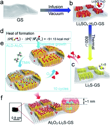
Unlike most of the Li2S cathodes employing commercial bulk Li2S,30,42 and organic lithium reagents43–46 as the starting materials, the lower cost, safer and more environmentally friendly GS and Li2SO4 were utilized as the raw materials to in situ form Li2S in this work. The Al2O3–Li2S–GS composites were synthesized as shown schematically in Fig. 1 (see the Experimental section for details). In brief, Li2SO4·H2O–GS composites were initially fabricated via the vacuum infusion of GS (Fig. 1a) circular pellets in Li2SO4 solution followed by rapid freezing and vacuum freeze-drying methods (Fig. 1b). The as-synthesized samples were heated at 800 °C in an argon atmosphere to allow the in situ formation of Li2S–GS (Fig. 1c).41,47–49 Afterwards, ultrathin Al2O3 films are grown by using the ALD technique because of its intrinsic versatility to form exceptionally conformal coatings with atomic-scale precision. To predict the growth location of Al2O3, the first-principles calculations were performed to evaluate the heat of formation of graphene–O and Li2S–O due to the growth mechanism of decomposition of O3 bond with the substrate first and then react with trimethyl aluminum to form Al2O3 (ref. 50). The heat of formation of Li2S–O was two times lower than that of graphene–O (ΔH = −51.13 kcal mol−1) (Fig. 1d), indicating the preferential adsorption of oxygen radicals on the surface of Li2S particles rather than graphene (Fig. 1e) leading to the preferential growth of Al2O3 on the surface of Li2S particles. Meanwhile, it is commonly accepted that the oxygen radicals can be more easily absorbed by the polar Li2S than the non-polar carbon of graphene.As a result, Li2S particles of Li2S–GS composites can be coated preferentially by Al2O3 (Fig. 1f). The thickness of Al2O3 films is able to be controlled facilely by the ALD–Al2O3 cycles. This simple and controllable method is a promising approach for large-scale preparation of high-performance Li2S cathodes. The GS framework with a well-defined and interconnected 3D porous network (Fig. S1†) is favorable for not only the infiltration of the electrolyte to accelerate the Li+ transport, but also the accommodation of the volume change of Li2S during charge/discharge cycling. Additionally, the superior robustness of the GS framework endows the composites with the ability to act as the free-standing cathode. The uniform dispersion of Li2SO4·H2O on the surface of graphene sheets (Fig. S2†), obtained by rapidly freezing the composite with liquid nitrogen and vacuum freeze drying, facilitates its complete reaction with carbon to generate Li2S.
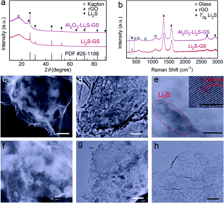
X-ray diffraction (XRD) pattern of Li2S–GS composites (Fig. 2a) shows the characteristic diffraction peaks of Li2S (JCPDS no. 26-1188). An XRD peak at 2θ = 25.7° is obviously detected, corresponding to the diffraction peak of the remaining reduced graphene oxide (rGO) sheets of the GS framework.40 A peak at 2θ = 22° arises from the Kapton tape, which is used to protect the samples from moisture during the testing procedure (Fig. S3a†). The Raman spectrum of Li2S–GS composites (Fig. 2b) presents the characteristic T2g peak of Li2S, the typical D-band and G-band peaks of rGO and the peaks of the glass holder (Fig. S3b†) used to protect Li2S from moisture during Raman characterization.34,35 The morphology analysis clearly shows that the Li2S–GS composites maintained the 3D structure of the GS framework (Fig. S4†). Compared to Li2SO4·H2O–GS composites, the distribution of Li2S particles on graphene sheets is uneven (Fig. 2c), owing to volume shrinking when Li2SO4·H2O converts into Li2S. Elemental mapping from energy-dispersive X-ray spectroscopy (EDX) of Li2S–GS composites (Fig. S5†) confirms the presence of carbon, sulfur and oxygen. The oxygen spectrum appears because of the oxygen of GS and the oxidation of Li2S during transferring samples from the poly/foil bags to the scanning electron microscope (SEM) chamber. Transmission electron microscopy (TEM) of Li2S–GS composites (Fig. 2d and e) and elemental mapping by TEM (Fig. S6†) are performed to verify the Li2S particle distribution on the surface of graphene sheets. The high resolution TEM (HRTEM) image of the Li2S in Li2S–GS composites (inset in Fig. 2e) shows the inter-planar spacing of 0.33 nm coinciding with that of the (111) plane of Li2S.
After ultrathin Al2O3 film coating, the phase composition of the as-prepared composites was characterized by XRD. As shown in Fig. 2a, the XRD peaks of Al2O3 are not observed due to the amorphous nature of Al2O3 by using an ALD technique.37 Furthermore, there are no redundant XRD peaks, revealing no side reaction during Al2O3 growth by ALD. The Li2S content of Al2O3–Li2S–GS composites showed little change (∼58 wt%), indicating a small percentage of Al2O3 in the composites. The SEM and TEM images of Al2O3–Li2S–GS composites (Fig. 2f and g) show the subtle structural alteration relative to Li2S–GS composites. From the elemental mapping of Al2O3–Li2S–GS composites (Fig. S7†), it is interesting to observe that Al2O3 exhibits a non-uniform distribution in composites. To clearly detect Al2O3, Al2O3–GS hybrids were obtained by the removal of Li2S from Al2O3–Li2S–GS composites. The ultrathin Al2O3 films are not visibly observed in the TEM image of Al2O3–GS hybrids (Fig. 2h) because of the ultrathin thickness (∼1 nm) and the amorphous nature. The robustness and elasticity of Al2O3–Li2S–GS cathodes are also investigated, which can be compressed-fit into a small enclosure and then recovers almost instantly to their original shape after release (Fig. S8a†). In addition, the thickness of the cathode film is 30–40 μm, which was directly prepared from the Al2O3–Li2S–GS cathode. The SEM images of the cross section of the Al2O3–Li2S–GS electrode were newly recorded, as shown in Fig. S8b.†
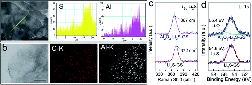
Aiming to investigate the distribution of Al2O3, the EDX line profiles (Fig. 3a) of Al2O3–Li2S–GS composites and elemental mapping (Fig. 3b) of Al2O3–GS hybrids strongly demonstrate that Al2O3 tends to grow on the surface of Li2S particles. The Al line profile and elemental mapping illustrate a regional distribution implying the preferential growth of Al2O3 on Li2S particles. This indicates that Al2O3–Li2S–GS composites possess a high electronic conductivity stemming from the graphene sheets without an Al2O3 coating. The remaining Al2O3–GS hybrids achieve a competitive conductivity of ∼160 S cm−1 compared to the remaining GS framework (∼162 S cm−1). The ultrathin Al2O3 film coating on Li2S–GS composites was also confirmed by Raman spectroscopy (Fig. 2b). For Al2O3–Li2S–GS composites, the peak for Al2O3 has not been detected due to its non-response to Raman spectroscopy51 The intensity of the Li2S T2g Raman peak is much weaker compared to that of the rGO peak, indicating that the Li2S particles are coated with Al2O3 films because of the surface-sensitive nature of Raman spectroscopy. By fitting Li2S T2g Raman peak (Fig. 3c), for Li2S–GS composites, the peak occurs at 372 cm−1, which agrees with the value in previous studies.34,35,52 However, the T2g peak position of Al2O3–Li2S–GS composites shifts towards a lower wave number to 367 cm−1. The decreasing frequency of the T2g peak hints a decrease in the force constant of Li–S bonds because of the T2g peak induced by the Li–S bond vibrations. To characterize the chemical interaction between Al2O3 and Li2S, X-ray photoelectron spectroscopy (XPS) measurement (Fig. 3d and S9†) was carried out. Compared to Li2S–GS composites, the Li 1 s spectrum of Al2O3–Li2S–GS composites shows slightly asymmetric broadening in the higher energy and an additive fitted peak with a higher binding energy of 55.4 eV arises (Fig. 3d), owing to Li–O interactions between Al2O3 and Li2S.34,53,54 The results of XPS and Raman analyses suggest that the strong polarity of oxygen radicals during ALD–Al2O3 cycles interacted with Li atoms in Li2S, verified by the first-principles calculations. Therefore, besides serving as a physical barrier to entrap Li2Sn, the ultrathin Al2O3 films preferentially coated on Li2S particles hold strong chemical interaction with Li2Sn to limit their dissolution as well. The preferential growth of ultrathin Al2O3 films and the binding interaction between Al2O3 and Li2S are favourable for improving the performance of cells since ultrathin Al2O3 films provide not only maintained conductivity which ensures the electron transfer pathway, but also a physical barrier and chemical interaction for suppressing the long-chain Li2Sn species dissolution, enabling excellent cycling stability.
Electrochemical performance
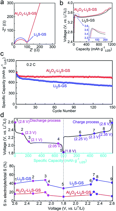
To determine the role of ultrathin Al2O3 films in promoting the electrochemical performance, both Li2S–GS and Al2O3–Li2S–GS electrodes were used as free-standing cathodes directly without a binder and collector to assemble cells with Li foil as the anode. The mass loading of Li2S is 1.2–1.5 mg cm−2. The cells were charged to 3.8 V at 0.05C (1C = 1166 mA g−1) in order to delithiate the Li2S, and then were cycled in the voltage range of 1.8–2.6 V. The discharge cutoff voltage was set to 1.8 V in order to avoid the irreversible capacity of the LiNO3 additive.55 The capacity derived from graphene and Al2O3 was negligible due to their inactive nature for the electrode in this voltage window.Electrochemical impedance spectroscopy (EIS) is employed to analyse the kinetics of the electrochemical reaction in our cell system. The semicircle in impedance spectra (Fig. 4a) of the as-assembled cells at the open-circuit potential corresponds to the charge transfer resistance (Rct), which is associated with the apparent energies (Ea) of the electrochemical reactions (Ea ∝ ln![[thin space (1/6-em)]](https://www.rsc.org/images/entities/char_2009.gif) Rct, details seen in the ESI†).19,56 The Rct value of Al2O3–Li2S–GS is 101.8 Ω, close to that of Li2S–GS (90.4 Ω), indicating that ultrathin Al2O3 films have little impact on the kinetics of the electrochemical reaction before cycling. The first charge voltage profiles of the as-assembled cells charged to 3.8 V at 0.05C to activate Li2S (Fig. 4b)16,57–59 exhibit the close potential barrier at 3.5–3.55 V (inset in Fig. 4b), and a long sloping plateau at 3.4–3.6 V corresponding to the anodic peak at ∼3.5 V in cyclic voltammetry (CV) tests (Fig. S10†). The EIS spectra, first charge voltage profiles and initial charge CV curves all demonstrate the negligible impact of ultrathin Al2O3 films on electron and Li+ ion transmission in electrochemical reactions in this work.
Rct, details seen in the ESI†).19,56 The Rct value of Al2O3–Li2S–GS is 101.8 Ω, close to that of Li2S–GS (90.4 Ω), indicating that ultrathin Al2O3 films have little impact on the kinetics of the electrochemical reaction before cycling. The first charge voltage profiles of the as-assembled cells charged to 3.8 V at 0.05C to activate Li2S (Fig. 4b)16,57–59 exhibit the close potential barrier at 3.5–3.55 V (inset in Fig. 4b), and a long sloping plateau at 3.4–3.6 V corresponding to the anodic peak at ∼3.5 V in cyclic voltammetry (CV) tests (Fig. S10†). The EIS spectra, first charge voltage profiles and initial charge CV curves all demonstrate the negligible impact of ultrathin Al2O3 films on electron and Li+ ion transmission in electrochemical reactions in this work.
After the initial charging, the as-assembled cells were cycled by galvanostatic measurement in the voltage window of 1.8–2.6 V at 0.2C. As shown in Fig. 4c, the Al2O3–Li2S–GS cathode exhibits a high initial specific capacity of 866 mA h gLi2S−1. The capacity at the 50th, 100th and 150th cycles can achieve 752, 762, and 736 mA h gLi2S−1 corresponding to the capacity retentions of 87%, 88% and 85%, respectively. By contrast, the Li2S–GS cathodes show a comparable initial specific capacity (824 mA h gLi2S−1), but much faster capacity decay at 0.2C (59% after 150 cycles). Thus, ultrathin Al2O3 films can suppress Li2Sn species dissolution, contributing to the superior cycling stability.
To prove the confining effect of ultrathin Al2O3 films, the sulfur content in the electrolyte was measured by using inductively coupled plasma-optical emission spectroscopy (ICP-OES, see the ESI† for details). The cells were cycled at 0.2C and disassembled at various charge/discharge states during the 20th cycle to measure the sulfur content in the electrolyte. As shown in Fig. 4d, points 1–9 represent the different discharge cutoff voltages (DCVs) and charge cutoff voltages (CCVs) during the 20th cycle. Points 2 and 4 refer to 2.30 V DCV and 2.05 V DCV, corresponding to the two potential plateaus. Points 5 and 9 refer to 1.8 V DCV and 2.6 V CCV, corresponding to the maximum discharge and charge capacity. From the ICP-OES results (Fig. 4d) of Al2O3–Li2S–GS cathodes, the sulfur percentages in the electrolyte are greatly decreased compared with Li2S–GS cathodes, corresponding to 17%, 13%, 14% and 14% at points 2, 4, 6 and 8, respectively. The dissolution of polysulfide in the electrolyte is markedly alleviated owing to the presence of ultrathin Al2O3 films. Therefore, Al2O3–Li2S–GS cells are able to achieve a more excellent stability.
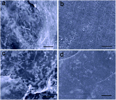
In addition, the structure of the electrode and the kinetics of electrochemical reactions are well maintained attributed to the restriction effect of ultrathin Al2O3 films on the dissolution of polysulfide. The morphology of the electrodes after the 150th discharge process was investigated, which were washed with dimethyl carbonate to remove the soluble species and dried naturally in an Ar-filled glovebox. In the case of Li2S–GS cathodes, a thick film of insoluble lithium sulfides is clearly observed on their surface, as well as the increasing size of active material particles (Fig. 5a). Compared with the original Li foil (Fig. S11†), the surface of Li anodes from Li2S–GS cells (Fig. 5b) exhibits a large number of lumps including the insoluble sulfur species and Li dendrites. The thick film and lumps, which are generated from the uncontrolled dissolution of polysulfide in the electrolyte, block the diffusivity of Li+ ions and passivate the surface of electrodes, leading to a large polarization and a low utilization of active materials.36,37 However, the Al2O3–Li2S–GS cathodes nearly preserve their original morphology without any obvious thick film on their surface (Fig. 5c). The surface of the Li anode is also smoother, which is ascribed to the effective confinement of polysulfide dissolution by ultrathin Al2O3 films (Fig. 5d), resulting in the high utilization of active materials. The morphology characterization of cathodes after repeated cycling strongly correlates with the results of EIS measurement (Fig. S12†). Compared with the results before cycling, Al2O3–Li2S–GS cells show a lower Rct value than that of Li2S–GS cells after the 150th discharge test at 0.2C indicating their better charge-transfer kinetics after 150 cycles. These results further confirm that the ultrathin Al2O3 films coated on Li2S particles are able to greatly suppress the dissolution of Li2Sn (4 ≤ n ≤ 8) species.
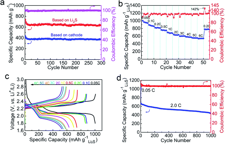
To further evaluate the electrochemical performance of Al2O3–Li2S–GS cathodes, their long-term cycling properties and rate capability were measured, as shown in Fig. 6. The Al2O3–Li2S–GS cathodes exhibited a stable cycling performance at 0.5C over 300 cycles (Fig. 6a), e.g. a high initial capacity of 728 mA h gLi2S−1 (∼1044 mA h gsulfur−1, 422 mA h gcathode−1), a reversible capacity of 643 mA h gLi2S−1 and a capacity retention of 88% after 300 cycles. The results are comparable to the work of Wang's group,19 which reported a capacity of 692 mA h gLi2S−1 after 145 cycles at 0.5C of nano-Li2S/rGO paper (652 mA h gLi2S−1 in our work) under the similar conditions of active material loading; however, we achieved a capacity retention of ∼90%, much higher than 77.1% of nano-Li2S/rGO paper. Due to their free-standing characteristics without a binder and collector, the Al2O3–Li2S–GS cathodes achieve a high capacity of 373 mA h gcathode−1 based on the mass of the cathode after 300 cycles at 0.5C. The average coulombic efficiency of Al2O3–Li2S–GS cathodes is ∼99% during cycling (Fig. 6a).
Importantly, for evaluating the rate capability and electrochemical kinetics of Al2O3–Li2S–GS cathodes, the cells were cycled at different C-rates from 0.05C to 6C and finally cycled at 0.2C (Fig. 6b). The Al2O3–Li2S–GS cathodes deliver stable capacities of 889, 810, 748, 703, 635, 589, 573 and 546 mA h gLi2S−1 as the C-rates increase from 0.1C to 5C, respectively. Even at a high C-rate of 6C, the Al2O3–Li2S–GS cathodes can attain a discharge specific capacity of ∼526 mA h gLi2S−1, delivering a competitive value compared with recently reported studies about Li2S cathodes (Fig. S13†). The stable coulombic efficiency is about ∼99.5% at various C-rates. After testing at a high C-rate, the Al2O3–Li2S–GS cathodes can still achieve a capacity of 778 mA h gLi2S−1 when the C-rate directly returns to 0.2C, demonstrating the excellent stability of cathodes. The discharge curve of Al2O3–Li2S–GS cathodes still shows two plateaus at 2.25 V and 1.85 V even at 6C (Fig. 6c).
We attribute the good rate performance of Al2O3–Li2S–GS cathodes to the following three reasons: first, the 3D interconnected porous structures of Al2O3–Li2S–GS cathodes provide a fast Li+ transport channel. Second, due to the preferential growth of Al2O3 ultrathin films on Li2S, rather than rGO, the high electrical conductivity of rGO sheets can be maintained, thereby facilitating electron transfer during the charging and discharging reactions. Third, the ultrathin Al2O3 films coated onto Li2S greatly limits the dissolution of polysulfide into the electrolyte, which is able to mitigate the possible loss of active materials, enhance the reversible capacity, and maintain the structural integrity of Al2O3–Li2S–GS cathodes. Therefore, considering the fast electron/ion transfer pathway, significantly suppressed polysulfide dissolution, and robust structural integrity of cathodes, the studied Al2O3–Li2S–GS cathodes are capable of providing excellent rate performance. The long-term cycling performance of Al2O3–Li2S–GS cathodes was tested at 2C after activating at 0.05C (Fig. 6d), it can exhibit a high initial capacity of 1028 mA h gLi2S−1 at 0.05C and 668 mA h gLi2S−1 at 2C. The reversible capacity at the end of the 100th, 500th and 1000th cycles delivers 600, 509, and 438 mA h gLi2S−1 with a low average capacity decay rate of 0.028% per cycle and a high average coulombic efficiency of ∼99%.
We have presented the electrochemical properties of free-standing Al2O3–Li2S–GS cathodes for Li/Li2S cells with 58 wt% Li2S and 10 ALD–Al2O3 cycles. For practical applications, the high loading of active materials with high electrochemical performance is desirable. Therefore, we altered the Li2S content and the thickness of Al2O3 films. Three different Li2S contents of Li2S–GS composites were synthesized and their morphology and cycling performance at 0.2C were investigated (Fig. S14†). Meanwhile, we investigated three different ALD–Al2O3 cycles: 5, 10 and 30 cycles; the morphology and cycling performance (at 0.2C) of the as-prepared composites are shown in Fig. S15.† Thus, these experiments illustrate our choice of 58 wt% Li2S and 10 ALD–Al2O3 cycles as the optimal composite structure.
Mechanism study
In order to understand the discharge mechanism of Al2O3–Li2S–GS cells and the role of Al2O3 during the charge/discharge process, we tracked the different states of the discharge process with the help of ex situ characterization. First of all, the charge/discharge voltage profiles (0.2C) of Al2O3–Li2S–GS and Li2S–GS cells were collected, as shown in Fig. S16.† The Li2S–GS cathodes exhibit two discharge plateaus corresponding to a two-step electrochemical process: ∼2.3 V and ∼2.05 V related to the formation of Li2Sn (4 ≤ n ≤ 8) and the conversion from Li2Sn to Li2S2 (or Li2S), respectively. However, for Al2O3–Li2S–GS cells, a supernumerary discharge plateau arises at ∼2.1 V, indicating a multistep sulfur reaction process. Aiming at a better understanding of the sulfur electrochemical reduction occurring in the Al2O3–Li2S–GS cells, the intermediate states of the electrolyte and Al2O3–Li2S–GS cathodes were investigated by ex situ measurements such as UV-vis spectroscopy,60–62 Raman spectroscopy,63–65 and XRD66–68 (see the ESI† for details).69 The corresponding results are shown in Fig. 7 and S17–S19.†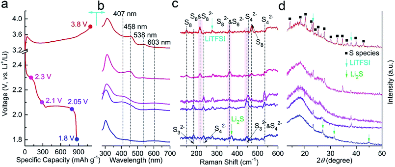 | ||
| Fig. 7 Ex situ measurements of Al2O3–Li2S–GS cathodes at (a) selected voltage states (3.8, 2.3, 2.1, 2.05 and 1.8 V); (b) UV-vis spectra, (c) Raman spectra and (d) XRD pattern. | ||
It is commonly accepted that the strong UV-Vis absorption bands at 603, 538, 458 and 407 nm correspond to S3˙−, S82−, S62− and S42−, respectively.59 It should be pointed out that S3˙− can be observed even at the end of discharge because of the disproportionation of polysulfide (Sn2− = [(2n − 2)/5]S3˙− + [(6 − n)/5]S2−). From the UV-Vis spectra (Fig. 7b), it is evident that the chain of polysulfide in the electrolyte shortens gradually along with the increasing discharge depth, which is observed at the Al2O3–Li2S–GS cathodes as well, according to the results of Raman (Fig. 7c) and XRD (Fig. 7d) measurements. Meanwhile, crystalline sulfur and Li2S in the cathodes are formed at the end states of the charge and discharge processes, respectively. According to the measurements above, the probable and compendious discharge reaction mechanism (Fig. S20†) for Al2O3–Li2S–GS cells was proposed as follows:
At the upper discharge plateau (2.3 V),
| S8 + 2Li+ + 2e− → Li2S8 |
| Li2S8 → Li2S6 + ¼S8 |
At the middle discharge plateau (2.1 V),
| 2Li2S6 + 2Li+ + 2e− → 3Li2S4 |
At the lower discharge plateau (1.8 V),
| 3Li2S4 + 2Li+ + 2e− → 4Li2S3 |
| 2Li2S3 + 2Li+ + 2e− → 3Li2S2 |
| Li2S2 + 2Li+ + 2e− → 2Li2S |
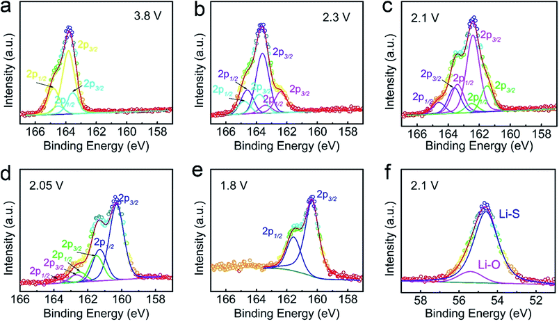
In terms of the additional discharge plateau, we propose that the primary reason for such a plateau stems from the interaction between Al2O3 and intermediate Li2Sn (4 ≤ n ≤ 8) species. For this purpose, XPS measurement was conducted to study the Al2O3–Li2S–GS cathodes at different charge/discharge states, as shown in Fig. 8 and S21–S23.† The fluorine and nitrogen elements stem from the electrolyte salt (LiTFSI) and additive (LiNO3), respectively. The XPS activity over 168 eV is detected, which is induced by the electrolyte (LiTFSI) because of no washing for the studied cathodes (Fig. S20 and S21†). It is interesting to note that the binding energy of S 2p peaks is decreasing with the increasing depth of the discharge process (from 3.8 to 1.8 V, as shown in Fig. 8a–e). The main reason for this phenomenon is the decreasing amount of the S–S component and the increasing Li–S component in polysulfide as the polysulfide chain shortens with continuous discharge. Additionally, the S 2p XPS peaks of pristine sulfur and Li2S are detected at 3.8 V and 1.8 V, respectively, revealing the formation of sulfur and Li2S at the end of the charge and discharge processes and agreeing well with the results of ex situ measurements in the former text. In order to investigate the interactions between Li2Sn species and Al2O3, the Li 1s XPS peaks of cathodes at different intermediate states are fitted (Fig. 8f and S23†). It is unsurprising that the Li–O binding stably exists throughout the charge/discharge process, indicating the persistent effect of Al2O3 on suppressing Li2Sn species dissolution. The similar argument is demonstrated in a previous study that anchoring materials (Al2O3 in our work) could induce strong binding interactions with intermediate Li2Sn species, and thus overcome their dissolution into the electrolyte, achieving long-term cycling stability and high-rate performance.70
As is well known, the Li2Sn (4 ≤ n ≤ 8) species under the upper plateaus (the plateau at ∼2.3 and 2.1 V) are highly unstable and soluble in the electrolyte, and they cause the shuttle effect and with the electrolyte solvent, resulting in the loss of active materials and gradual capacity degradation. On the other hand, the capacity of the lower plateau (at ∼2.05 V), dominated by the capacity of electrode, is deeply dependent on the upper plateau. Therefore, stabilizing Li2Sn (4 ≤ n ≤ 8) species and suppressing their dissolution are crucial for improving the performance of the electrode. Compared to Li2S–GS cells, for which the upper plateau as well as the lower plateau shrink severely with prolonged cycling (Fig. S16†), the capacity of Al2O3–Li2S–GS cells can be mainly attributed to the confinement effect of ultrathin Al2O3 films on long-chain polysulfides.
Conclusions
In summary, we have demonstrated the preferential growth of Al2O3 on the surface of Li2S particles in free-standing Li2S–GS composites by using an ALD technique. The porous GS framework without an Al2O3 coating provides excellent electronic and ionic conductivity. Besides acting as a physical barrier to entrap Li2Sn, ultrathin Al2O3 films coated on the surface of Li2S particles also exhibit strong binding interaction with polysulfides to effectively suppress their dissolution. Therefore, for Al2O3–Li2S–GS cells, the capacity is maintained, resulting in an excellent stability. The free-standing Al2O3–Li2S–GS cathodes are able to achieve a high capacity of 736 mA h gLi2S−1 with a high capacity retention of 85%, much higher than that of Li2S–GS cathodes (59%). In addition, Al2O3–Li2S–GS cathodes can deliver a capacity of 643 mA h gLi2S−1 (373 mA h gcathode−1) with a high capacity retention of 88% after 300 cycles at 0.5C and a low capacity decay rate of 0.028% per cycle during 1000 cycles at 2C. This work provides a new approach for coating Li2S particles to obtain high-performance Li2S cathodes.Acknowledgements
This work was supported by the National Natural Science Foundation of China (No. 51572060 and 51502062), China Postdoctoral Science Foundation Funded Project (No. 2016M590279), the Fundamental Research Funds for the Central Universities (No. HIT.BRETIII.201224 and 201312) and Program for Innovation Research of Science in Harbin Institute of Technique (PIRS of HIT-No. 201506). Excellent Youth Foundation of Heilongjiang Scientific Committee (No. JC2015010). G. Wu acknowledges the start-up funding from the University at Buffalo (SUNY) along with the National Science Foundation (CBET-1604392).References
- B. Scrosati, J. Hassoun and Y. K. Sun, Energy Environ. Sci., 2011, 4, 3287–3295 CAS.
- L. B. Hu, J. W. Choi, Y. Yang, S. Jeong, F. La Mantia, L. F. Cui and Y. Cui, Proc. Natl. Acad. Sci. U. S. A., 2009, 106, 21490–21494 CrossRef CAS PubMed.
- X. L. Ji and L. F. Nazar, J. Mater. Chem., 2010, 20, 9821–9826 RSC.
- A. Manthiram, Y. Z. Fu, S. H. Chung, C. X. Zu and Y. S. Su, Chem. Rev., 2014, 114, 11751–11787 CrossRef CAS PubMed.
- Z. Li, H. B. Wu and X. W. Lou, Energy Environ. Sci., 2016, 9, 3061–3070 CAS.
- R. Cao, W. Xu, D. Lv, J. Xiao and J.-G. Zhang, Adv. Energy Mater., 2015, 5, 1402273–1402295 CrossRef.
- S. Urbonaite, T. Poux and P. Novák, Adv. Energy Mater., 2015, 5, 1500118–1500123 CrossRef.
- M. S. Whittingham, Chem. Rev., 2004, 104, 4271–4301 CrossRef CAS PubMed.
- H. Jha, I. Buchberger, X. Y. Cui, S. Meini and H. A. Gasteiger, J. Electrochem. Soc., 2015, 162, A1829–A1835 CrossRef CAS.
- N. A. Liu, L. B. Hu, M. T. McDowell, A. Jackson and Y. Cui, ACS Nano, 2011, 5, 6487–6493 CrossRef CAS PubMed.
- M. Agostini, J. Hassoun, J. Liu, M. Jeong, H. Nara, T. Momma, T. Osaka, Y. K. Sun and B. Scrosati, ACS Appl. Mater. Interfaces, 2014, 6, 10924–10928 CAS.
- J. Hassoun and B. Scrosati, Angew. Chem., Int. Ed., 2010, 49, 2371–2374 CrossRef CAS PubMed.
- J. Hassoun, Y. K. Sun and B. Scrosati, J. Power Sources, 2011, 196, 343–348 CrossRef CAS.
- G. Q. Ma, Z. Y. Wen, M. F. Wu, C. Shen, Q. S. Wang, J. Jin and X. W. Wu, Chem. Commun., 2014, 50, 14209–14212 RSC.
- J. Bruckner, S. Thieme, F. Bottger-Hiller, I. Bauer, H. T. Grossmann, P. Strubel, H. Althues, S. Spange and S. Kaskel, Adv. Funct. Mater., 2014, 24, 1284–1289 CrossRef.
- Y. Son, J. S. Lee, Y. Son, J. H. Jang and J. Cho, Adv. Energy Mater., 2015, 5, 1500110–1500123 CrossRef.
- S. Jeong, D. Bresser, D. Buchholz, M. Winter and S. Passerini, J. Power Sources, 2013, 235, 220–225 CrossRef CAS.
- J. C. Guo, Z. C. Yang, Y. C. Yu, H. D. Abruna and L. A. Archer, J. Am. Chem. Soc., 2013, 135, 763–767 CrossRef CAS PubMed.
- C. Wang, X. S. Wang, Y. Yang, A. Kushima, J. T. Chen, Y. H. Huang and J. Li, Nano Lett., 2015, 15, 1796–1802 CrossRef CAS PubMed.
- S. Meini, R. Elazari, A. Rosenman, A. Garsuch and D. Aurbach, J. Phys. Chem. Lett., 2014, 5, 915–918 CrossRef CAS PubMed.
- R. Xu, X. F. Zhang, C. Yu, Y. Ren, J. C. M. Li and I. Belharouak, ChemSusChem, 2014, 7, 2457–2460 CrossRef CAS PubMed.
- J. T. Zhang, H. Hu, Z. Li and X. W. Lou, Angew. Chem., Int. Ed., 2016, 55, 3982–3986 CrossRef CAS PubMed.
- Z. Li, J. T. Zhang, Y. M. Chen, J. Li and X. W. Lou, Nat. Commun., 2015, 6, 8850–8857 CrossRef CAS PubMed.
- K. P. Cai, M. K. Song, E. J. Cairns and Y. G. Zhang, Nano Lett., 2012, 12, 6474–6479 CrossRef CAS PubMed.
- L. M. Suo, Y. J. Zhu, F. D. Han, T. Gao, C. Luo, X. L. Fan, Y. S. Hu and C. S. Wang, Nano Energy, 2015, 13, 467–473 CrossRef CAS.
- C. Y. Nan, Z. Lin, H. G. Liao, M. K. Song, Y. D. Li and E. J. Cairns, J. Am. Chem. Soc., 2014, 136, 4659–4663 CrossRef CAS PubMed.
- Y. Z. Fu, C. X. Zu and A. Manthiram, J. Am. Chem. Soc., 2013, 135, 18044–18047 CrossRef CAS PubMed.
- L. Chen, Y. Z. Liu, M. Ashuri, C. H. Liu and L. L. Shaw, J. Mater. Chem. A, 2014, 2, 18026–18032 CAS.
- F. X. Wu, J. T. Lee, F. F. Fan, N. Nitta, H. Kim, T. Zhu and G. Yushin, Adv. Mater., 2015, 27, 5579–5586 CrossRef CAS PubMed.
- F. X. Wu, J. T. Lee, E. B. Zhao, B. Zhang and G. Yushin, ACS Nano, 2016, 10, 1333–1340 CrossRef CAS PubMed.
- M. Wu, Y. Cui and Y. Z. Fu, ACS Appl. Mater. Interfaces, 2015, 7, 21479–21486 CAS.
- G. M. Zhou, E. Paek, G. S. Hwang and A. Manthiram, Adv. Energy Mater., 2016, 6, 1501355–1501363 CrossRef.
- D. Sun, Y. Hwa, Y. Shen, Y. Huang and E. J. Cairns, Nano Energy, 2016, 26, 524–532 CrossRef CAS.
- Z. W. Seh, H. T. Wang, P. C. Hsu, Q. F. Zhang, W. Y. Li, G. Y. Zheng, H. B. Yao and Y. Cui, Energy Environ. Sci., 2014, 7, 672–676 CAS.
- Z. W. Seh, J. H. Yu, W. Y. Li, P. C. Hsu, H. T. Wang, Y. M. Sun, H. B. Yao, Q. F. Zhang and Y. Cui, Nat. Commun., 2014, 5, 5017–5024 CrossRef CAS PubMed.
- H. Kim, J. T. Lee, D. C. Lee, A. Magasinski, W. I. Cho and G. Yushin, Adv. Energy Mater., 2013, 3, 1308–1315 CrossRef CAS.
- M. P. Yu, W. J. Yuan, C. Li, J. D. Hong and G. Q. Shi, J. Mater. Chem. A, 2014, 2, 7360–7366 CAS.
- X. G. Han, Y. H. Xu, X. Y. Chen, Y. C. Chen, N. Weadock, J. Y. Wan, H. L. Zhu, Y. L. Liu, H. Q. Li, G. Rubloff, C. S. Wang and L. B. Hu, Nano Energy, 2013, 2, 1197–1206 CrossRef CAS.
- M. P. Yu, A. J. Wang, F. Y. Tian, H. Q. Song, Y. S. Wang, C. Li, J. D. Hong and G. Q. Shi, Nanoscale, 2015, 7, 5292–5298 RSC.
- S. Lu, Y. Chen, X. Wu, Z. Wang and Y. Li, Sci. Rep., 2014, 4, 4629–4633 Search PubMed.
- Z. Li, S. G. Zhang, C. Zhang, K. Ueno, T. Yasuda, R. Tatara, K. Dokko and M. Watanabe, Nanoscale, 2015, 7, 14385–14392 RSC.
- F. M. Ye, Y. Hou, M. N. Liu, W. F. Li, X. W. Yang, Y. C. Qiu, L. S. Zhou, H. F. Li, Y. J. Xua and Y. G. Zhang, Nanoscale, 2015, 7, 9472–9476 RSC.
- Z. Lin, C. Y. Nan, Y. F. Ye, J. H. Guo, J. F. Zhu and E. J. Cairns, Nano Energy, 2014, 9, 408–416 CrossRef CAS.
- Y. Hwa, J. Zhao and E. J. Cairns, Nano Lett., 2015, 15, 3479–3486 CrossRef CAS PubMed.
- Y. Yang, M. T. McDowell, A. Jackson, J. J. Cha, S. S. Hong and Y. Cui, Nano Lett., 2010, 10, 1486–1491 CrossRef CAS PubMed.
- X. B. Meng, D. J. Comstock, T. T. Fister and J. W. Elam, ACS Nano, 2014, 8, 10963–10972 CrossRef CAS PubMed.
- Z. C. Yang, J. C. Guo, S. K. Das, Y. C. Yu, Z. H. Zhou, H. D. Abruna and L. A. Archer, J. Mater. Chem. A, 2013, 1, 1433–1440 CAS.
- M. Kohl, J. Bruckner, I. Bauer, H. Althues and S. Kaskel, J. Mater. Chem. A, 2015, 3, 16307–16312 CAS.
- S. Zhang, M. N. Liu, F. Ma, F. M. Ye, H. F. Li, X. Y. Zhang, Y. Hou, Y. C. Qiu, W. F. Li, J. Wang, J. Wang and Y. G. Zhang, J. Mater. Chem. A, 2015, 3, 18913–18919 CAS.
- M. B. M. Mousa, C. J. Oldham and G. N. Parsons, Langmuir, 2014, 30, 3741–3748 CrossRef CAS PubMed.
- A. Mortensen, D. H. Christensen, O. F. Nielsen and E. Pedersen, J. Raman Spectrosc., 1991, 22, 47–49 CrossRef CAS.
- Z. W. Seh, H. T. Wang, N. Liu, G. Y. Zheng, W. Y. Li, H. B. Yao and Y. Cui, Chem. Sci., 2014, 5, 1396–1400 RSC.
- J. F. Moulder, W. F. Stickle, P. E. Sobol and K. D. Bomben, Physical Electronics Division, Perkin-Elmer Corp., 1995, pp. 33–34 Search PubMed.
- F. X. Wu, J. T. Lee, N. Nitta, H. Kim, O. Borodin and G. Yushin, Adv. Mater., 2015, 27, 101–108 CrossRef CAS PubMed.
- S. S. Zhang, Electrochim. Acta, 2012, 70, 344–348 CrossRef CAS.
- K. Zhang, L. J. Wang, Z. Hu, F. Y. Cheng and J. Chen, Sci. Rep., 2014, 4, 6467–6473 CrossRef CAS PubMed.
- Y. Yang, G. Y. Zheng, S. Misra, J. Nelson, M. F. Toney and Y. Gui, J. Am. Chem. Soc., 2012, 134, 15387–15394 CrossRef CAS PubMed.
- L. Wang, Y. G. Wang and Y. Y. Xia, Energy Environ. Sci., 2015, 8, 1551–1558 CAS.
- S. Walus, C. Barchasz, R. Bouchet, J. F. Martin, J. C. Lepretre and F. Alloin, Electrochim. Acta, 2015, 180, 178–186 CrossRef CAS.
- C. Barchasz, F. Molton, C. Duboc, J. C. Lepretre, S. Patoux and F. Alloin, Anal. Chem., 2012, 84, 3973–3980 CrossRef CAS PubMed.
- R. Dominko, M. U. M. Patel, V. Lapornik, A. Vizintin, M. Kozelj, N. N. Tusar, I. Arcon, L. Stievano and G. Aquilanti, J. Phys. Chem. C, 2015, 119, 19001–19010 CAS.
- N. A. Canas, D. N. Fronczek, N. Wagner, A. Latz and K. A. Friedrich, J. Phys. Chem. C, 2014, 118, 12106–12114 CAS.
- M. Hagen, P. Schiffels, M. Hammer, S. Dorfler, J. Tubke, M. J. Hoffmann, H. Althues and S. Kaskel, J. Electrochem. Soc., 2013, 160, A1205–A1214 CrossRef CAS.
- H. L. Wu, L. A. Huff and A. A. Gewirth, ACS Appl. Mater. Interfaces, 2015, 7, 1709–1719 CAS.
- J. T. Yeon, J. Y. Jang, J. G. Han, J. Cho, K. T. Lee and N. S. Choi, J. Electrochem. Soc., 2012, 159, A1308–A1314 CrossRef CAS.
- S. Walus, C. Barchasz, J. F. Colin, J. F. Martin, E. Elkaim, J. C. Lepretre and F. Alloin, Chem. Commun., 2013, 49, 7899–7901 RSC.
- N. A. Canas, S. Wolf, N. Wagner and K. A. Friedrich, J. Power Sources, 2013, 226, 313–319 CrossRef CAS.
- J. Nelson, S. Misra, Y. Yang, A. Jackson, Y. J. Liu, H. L. Wang, H. J. Dai, J. C. Andrews, Y. Cui and M. F. Toney, J. Am. Chem. Soc., 2012, 134, 6337–6343 CrossRef CAS PubMed.
- M. Wild, L. O'Neill, T. Zhang, R. Purkayastha, G. Minton, M. Marinescu and G. J. Offer, Energy Environ. Sci., 2015, 8, 3477–3494 CAS.
- Q. F. Zhang, Y. P. Wang, Z. W. Seh, Z. H. Fu, R. F. Zhang and Y. Cui, Nano Lett., 2015, 15, 3780–3786 CrossRef CAS PubMed.
Footnotes |
| † Electronic supplementary information (ESI) available. See DOI: 10.1039/c6ta08039a |
| ‡ These two authors contributed equally to this work. |
| This journal is © The Royal Society of Chemistry 2017 |

