
 Open Access Article
 This Open Access Article is licensed under a
 Creative Commons Attribution 3.0 Unported Licence
Optimising low molecular weight hydrogels for automated 3D printing†
Michael C.
Nolan
 ab,
Ana M.
Fuentes Caparrós
ac,
Bart
Dietrich
a,
Michael
Barrow
b,
Emily R.
Cross
a,
Markus
Bleuel
de,
Stephen M.
King
f and
Dave J.
Adams
*a
ab,
Ana M.
Fuentes Caparrós
ac,
Bart
Dietrich
a,
Michael
Barrow
b,
Emily R.
Cross
a,
Markus
Bleuel
de,
Stephen M.
King
f and
Dave J.
Adams
*a
aSchool of Chemistry, University of Glasgow, Glasgow, G12 8QQ, UK. E-mail: dave.adams@glasgow.ac.uk
bDepartment of Chemistry, University of Liverpool, Liverpool L69 7ZD, UK
cDepartment of Chemical Engineering, Faculty of Sciences, 18071 Granada, Spain
dNIST Center for Neutron Research, National Institute of Science and Technology, Gaithersburg, MD 20988-8562, USA
eDepartment of Materials Science and Engineering, University of Maryland, College Park, MD 20742-2115, USA
fSTFC Pulsed Neutron and Muon Source, Science and Technology Facilities Council, Rutherford Appleton Laboratory, Harwell Campus, Didcot, OX11 0QX, UK
First published on 26th October 2017
Abstract
Hydrogels prepared from low molecular weight gelators (LMWGs) are formed as a result of hierarchical intermolecular interactions between gelators to form fibres, and then further interactions between the self-assembled fibres via physical entanglements, as well as potential branching points. These interactions can allow hydrogels to recover quickly after a high shear rate has been applied. There are currently limited design rules describing which types of morphology or rheological properties are required for a LMWG hydrogel to be used as an effective, printable gel. By preparing hydrogels with different types of fibrous network structures, we have been able to understand in more detail the morphological type which gives rise to a 3D-printable hydrogel using a range of techniques, including rheology, small angle scattering and microscopy.
Introduction
The controlled shaping and delivery of hydrogels has many potential applications such as tissue engineering,1 drug delivery,2–6 and optoelectronics.7,8 3D printers can allow for the reproducible, controlled and automatic delivery of materials within a 3D space without the need for moulds.9 3D printing technology has improved dramatically over recent years with the development of high resolution techniques using a range of materials and delivery mechanisms.10–12 Extrusion-based 3D printers are now cheap and readily accessible to small scale laboratories and can be adapted for specific needs.13 This has led to a vast increase in investigations into printing new materials with interesting applications. Extrusion printing is generally used for viscous materials and can result in a continuous 3D network if the material and printing parameters are optimised.14 There has been extensive research in the extrusion of peptides and polymer blends using precursor solutions which form hydrogels after extrusion via processes such as UV curing,15–18 addition of crosslinking salts,17 the submersion into a gel or solution,19 and changing the temperature.20 However, 3D printing of hydrogels prepared from low molecular weight gelators (LMWGs) is far less common, and understanding and developing the processing techniques for these materials can have significant potential applications in forming complex hierarchical structures for tissue engineering.21,22A supramolecular gel network formed via non-covalent interactions would allow for the reversible breaking and recovery of the network.23 When a gel is pre-formed inside a syringe and then extruded, the printing process relies on both thixotropy and the recovery of the mechanical properties of the gel which, in turn, greatly relies on the microstructure of the gel network.24,25 Huang et al. have shown that the recovery after shear in organogel systems can depend on the gel microstructure, which in turn depends on the conditions under which gelation is carried out.26 Similarly, Pochan and co-workers studied hydrogel behaviour during and after flow and showed that planar domains of the gel network break apart to allow the gel to flow.24 Using a preformed gel that recovers quickly reduces the need for the additional treatment of the extruded precursor solution to form a gel. This approach opens up opportunities to encapsulate drugs, catalysts and other materials inside the gel which will not leak from the network if the network recovers quickly after extrusion.24,27 Using hydrogels as cell carriers has also been shown to improve cell viability during bio-printing.28
Most reported examples of hydrogels suitable for printing have been discovered through serendipity. In general, why some gels are thixotropic and others are not is not well understood. There is a need to understand the link between the microstructure of the gel network and its printability, where the ability to print the gel is considered as the ability to recover a continuous gel network with a reasonable resolution after extrusion. The challenge is to be able to develop design rules to guide the selection of the correct LMWG and network type to attain the desired printed gel properties.
Hydrogels formed from LMWGs can be prepared under different conditions to give different mechanical properties.29–33 To improve the recovery of hydrogels after extrusion, it is common to increase the gelator concentration to increase the concentration of fibres and crosslinking.9 However, it is also understood that using different gelation triggers, such as a pH change or the addition of an anti-solvent, leads to different mechanical properties due to the formation of different gel microstructures.29,34 In this study, the recoverability and printability of different gel microstructures are compared. Our aim is to form an understanding as to which gel microstructures are desirable when developing printable low molecular weight hydrogels.
Results and discussion
In order to create a comprehensive study on LMWG hydrogel recoverability, four carefully selected gels were studied. As previously mentioned, LMWG which form printable hydrogels are usually found by trial and error. Therefore, initially, we carried out a broad study on the recovery of mechanical properties within our library of gelators. Over ten different gelators were tested along with the three different gelation triggers using solvent, salt and pH switches. The recovery properties were measured using rheometry with a vane and cup geometry in which a high shear rate was applied and the recovery of the storage modulus, G′, was monitored. This revealed several gelators which formed gels that could be printed. From these, we chose two gelators for this study, 3-phenyl-2-[3-phenyl-2-[2-(5,6,7,8-tetrahydronaphthalen-1-yloxy)acetamido]propanamido]propanoic acid (1) and Fmoc-diphenylalanine (2), Scheme 1.35 The synthesis of these gelators and the materials used are described in the ESI.† | ||
| Scheme 1 The structures of the two LMWG used here. | ||
Two different methods were used to form hydrogels from these LMWGs. In the first method, the LMWG was dissolved in DMSO to a concentration of 16.7 mg mL−1. Water was then added to provide a final concentration of the LMWG of 5 mg mL−1, a volume percentage of DMSO of 30 vol% and a final pH of 5.9. This solvent-triggered approach33,36,37 provided gels 1a and 2a respectively from the two LMWG. Alternatively, solutions of the LMWGs at pH 11.8 for 1 and pH 9.9 for 2 were prepared by the careful addition of sodium hydroxide solution to a dispersion of the LMWGs in water (here, it is necessary to carefully control the pH as deprotection of the Fmoc group occurs at high pH). The pH of these solutions was then lowered by the addition of glucono-δ-lactone (GdL). GdL hydrolyses slowly in solution which results in a slow homogeneous acidification of the solution to form the gel at pH 3.6.38,39 This pH-triggered approach afforded gels 1b and 2b from the two LMWGs respectively. The different gelation triggers are expected to result in the formation of different microstructures of the gel network which we expected to show different recovery properties when extruded from a syringe.14,25,33 All gels were formed directly inside 10 mL polypropylene syringes.
When gels are extruded from a syringe, a range of properties need to be considered and evaluated. First, the rheological properties of the gels should be tested in order to see if the gel is able to recover after it is exposed to a high shear rate. Oscillatory rheology can be used as a tool for understanding if gels are able to recover upon an oscillatory shear, however this may not be fully representative of the type of shear found inside a syringe during extrusion.24 Other structural characterisation techniques such as microscopy and small angle neutron scattering (SANS) have proven useful in observing the structure of gels and can be used in conjunction with rheology to gain a thorough understanding of the materials before and after extrusion.24,40 Here, we have characterised the gels using rheological, microscopy, and scattering techniques, to understand the effect of extrusion on the gels.
The 3D printer used here is described in detail in the ESI.† The shear rate the gel encounters as it is extruded from the syringe can be calculated using eqn (1),24,41 where 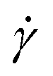 is the shear rate (in s−1), V is the volume of extruded gel (in m3), r is the radius of the nozzle (in m) and t is the time taken to extrude the volume of gel (in s).
 | (1) |
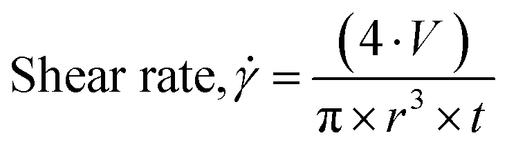
A typical extrusion rate using the 3D printer in this configuration is 835 μL s−1 through the nozzle of a syringe with an internal diameter of 0.8 mm, which results in a shear rate of ca. 16![[thin space (1/6-em)]](https://www.rsc.org/images/entities/char_2009.gif) 000 s−1. The automation of the 3D printer allowed for accurate control over the flow rate of the gel during extrusion and eqn (1) was used to relate all prints to a known shear rate. The gelator solutions were added to a syringe, allowed to gel for 18 hours and then extruded automatically using a 3D printer (Fig. S8 ESI,†Fig. 1). A stronger or more viscous material will require a higher shear rate to extrude from the syringe and the stress applied to the gel will have an impact on the resulting structure. Lines of 6 cm length were printed of gels 1a, 1b and 2a, 2b by extruding 200 μL of gel (Fig. S8, ESI†). It quickly became clear that the pH-triggered gels (1b and 2b) needed a higher shear rate to be successfully extruded from the syringe, which was achieved by extruding 400 μL of gel instead of 200 μL. The printing of a 6 cm line took 0.24 seconds and at lower shear rates only solution is extruded from the gel. This observation is in agreement with compression tests on Fmoc-dipeptide hydrogels, which showed that solution is expelled from the gel when a slowly increasing force is applied, however the gel undergoes a brittle break when compressed quickly which could allow the gel to flow.42 As the solvent-triggered gels 1a and 2a could be extruded using lower shear rates this resulted in more continuous and reproducible lines of prints (Table S1, ESI†). Different concentrations of gels of 2a were also prepared and their prints optimised (Fig. S9, ESI†).
000 s−1. The automation of the 3D printer allowed for accurate control over the flow rate of the gel during extrusion and eqn (1) was used to relate all prints to a known shear rate. The gelator solutions were added to a syringe, allowed to gel for 18 hours and then extruded automatically using a 3D printer (Fig. S8 ESI,†Fig. 1). A stronger or more viscous material will require a higher shear rate to extrude from the syringe and the stress applied to the gel will have an impact on the resulting structure. Lines of 6 cm length were printed of gels 1a, 1b and 2a, 2b by extruding 200 μL of gel (Fig. S8, ESI†). It quickly became clear that the pH-triggered gels (1b and 2b) needed a higher shear rate to be successfully extruded from the syringe, which was achieved by extruding 400 μL of gel instead of 200 μL. The printing of a 6 cm line took 0.24 seconds and at lower shear rates only solution is extruded from the gel. This observation is in agreement with compression tests on Fmoc-dipeptide hydrogels, which showed that solution is expelled from the gel when a slowly increasing force is applied, however the gel undergoes a brittle break when compressed quickly which could allow the gel to flow.42 As the solvent-triggered gels 1a and 2a could be extruded using lower shear rates this resulted in more continuous and reproducible lines of prints (Table S1, ESI†). Different concentrations of gels of 2a were also prepared and their prints optimised (Fig. S9, ESI†).
 | ||
| Fig. 1 Photographs of optimised 3D printed gels of (a) 1a, (b) 1b, (c) 2a, and (d) 2b. 3D printed gels of 2a mixed with dyes Nile Blue (0.5 mg mL−1) or methyl orange (0.25 mg mL−1) and printed side by side (e and f) and one on top of the other (g and h). The scale bar represents 1 cm in all cases. | ||
The 3D printer has several parameters which can be optimised for printing the gels (the volume of the gel to extrude, the speed of the extrusion, the height of the accessory from the printing bed and the speed the printing accessory moves along the axes during printing).43 Each parameter was systematically changed and optimised for each gel. The printing parameters were optimised by extruding a constant volume of 4 μL mm−1 at speeds of 5, 10, 15, 20 and 25k mm min−1. The optimal speed was defined as the line of the thinnest continuous gel. Then, lines were printed using a constant optimal speed and volumes of 1–10 μL mm−1 and the thinnest continuous line chosen. A line of each gel was printed using the optimal conditions for each gel and photographed (Fig. 1a–d). The optimal resolution for the printed gels was 4 × 4 × 1 mm in the x, y and z axes.
When comparing lines printed using the optimised parameters, more continuous gel structures were observed using the solvent-triggered gels 1a and 2a compared to the pH-triggered gels 1b and 2b. Gel 2a was then mixed with dyes and printed side by side to show the versatility of the printing method in printing pre-programmed structures (Fig. 1e–h). We were able to print gels of 3–6 layers, which could be removed from the plate and manipulated (Fig. 2a–f). Here, the layers acted as if they were fused together and the colours stayed in well-defined regions. Only the colour on the bottom layer became less defined due to the weight of the structure on top.
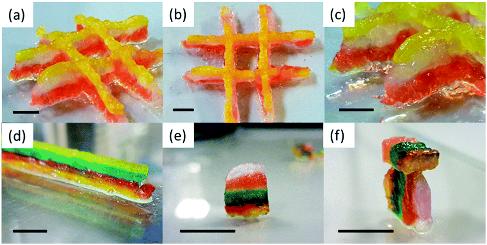 | ||
| Fig. 2 Photographs of 3D printed gels of 2a with dyes mixed in to show the different layers. (a–c) A three-layered structure; (d–f) a six-layered structure. Sections were removed using a scalpel and oriented in different ways (e–f). Scale bar represents 1 cm in all cases. | ||
A key question is why gels formed by the different triggers can be printed with different success. To explain this, we first turned to confocal microscopy (Fig. 3). Although the resolution of this technique is not suitable for examining the individual fibres that lead to gelation, it is possible to probe the gel microstructure.30 We examine the differences before and after extrusion. Before extrusion, the solvent-triggered gels show the presence of spherulitic domains, in keeping with our previous reports.33,44 The domains were much smaller for 1a as compared to 2a. After extrusion, similar domains were observed, although in both cases there was an increase in domain size. Pochan and co-workers reported that bundles of fibres, described as fibrils, have a random orientation during gel flow.24 Similarly, Huang et al. have shown that spherulitic structures result in thixotropic gels.26 Tomasini and co-workers also commented that hydrogels with denser fibrous networks are affected to a greater extent by the application of high shear.25 Therefore, we suggest that the spherical-like domains of 1a and 2a formed from the solvent-triggered gelation method can greatly reduce the effect of the random orientations during flow and hence allow these gels to be effectively printed. The pH-triggered gels before extrusion have greater uniformity than the solvent-triggered gels, which again is consistent with our data elsewhere.31 After extrusion however, there is a significant decrease in homogeneity. The data for 1b especially shows a significant change in the apparent ordering of the underlying fibres and changes in the gel microstructure. Similar effects are observed for 2b. These changes can be linked to the loss of homogeneity of the gel after extrusion in the microscopy.
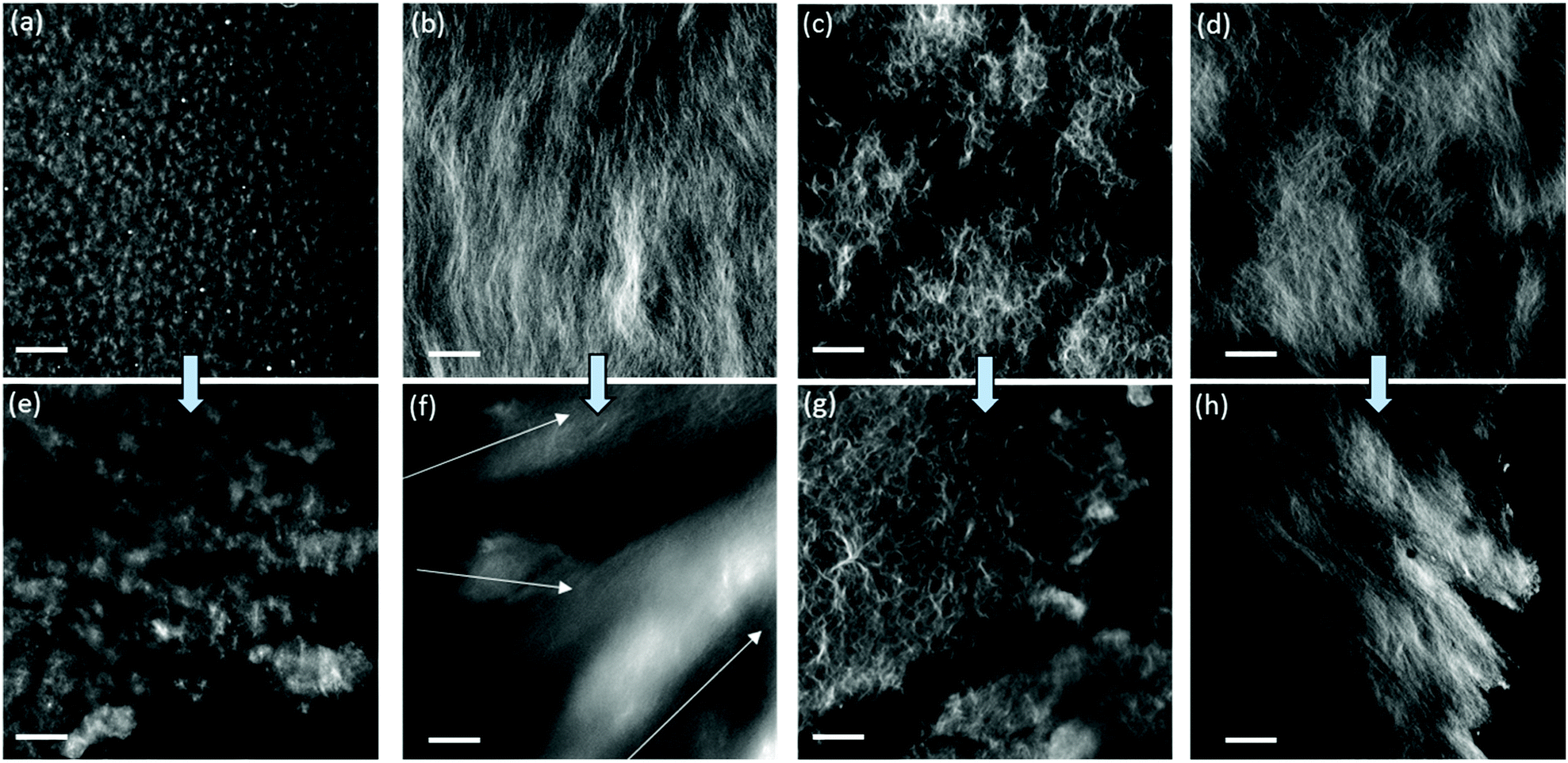 | ||
| Fig. 3 Confocal microscope images of (a) 1a; (b) 1b; (c) 2a; (d) 2b. (e–h) are images of the gels after extrusion from a syringe. Gelator solutions were stained with Nile Blue before gels were formed. The arrows in (f) are a suggestion of different orientations of structures inside the gel. The scale bars represent 20 μm. | ||
The confocal microscopy data were supported with small-angle neutron scattering (SANS) and ultra small-angle neutron scattering (USANS) data (Fig. 4). The data was fitted using the SasView software using the power law and the Kratky-Porod flexible cylinder models (Fig. S10, ESI†) which have been used in the past to fit the scattering data for similar hydrogels.30,31,45–47 For the gels here, the scattering in the SANS regime at Q = 4 nm−1 to 0.06 nm−1 suggest cylinder-like structures on the nanoscale, such as fibres and fibrils, which are unchanged after extrusion. The survival of the primary fibre structure is also inferred by the confocal microscopy where similar sizes of fibres are observed across all samples when comparing them before and after extrusion (see Fig. 3). For gels 2a and 2b, a larger radius was used for fitting the flexible cylinder model (Table S2, ESI†). We hypothesise that it is the bundles of fibres that are responsible for the larger radius (and less pronounced oscillations in the SANS). Consequently, a radius polydispersity factor (= standard deviation/mean) of 0.2 was needed to fit the feature in the scattering at 0.6 nm−1, suggesting a range of radii are present from various fibril sizes. The fits using polydispersity are displayed in Fig. S11 (ESI†).
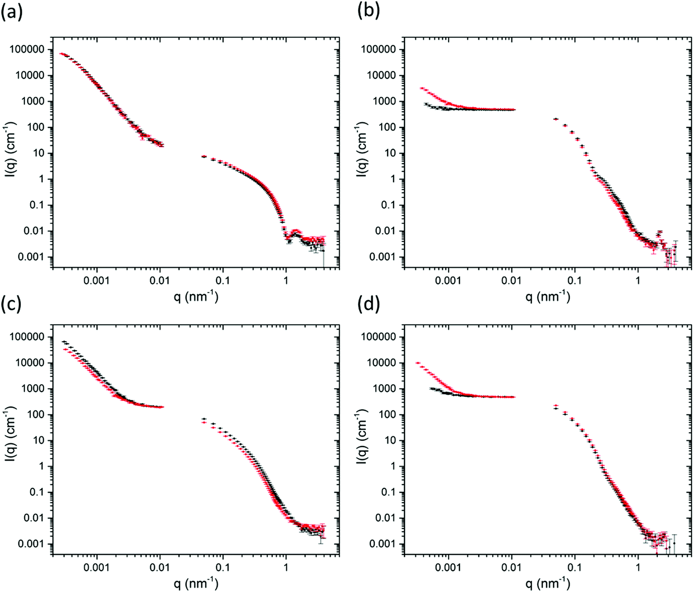 | ||
| Fig. 4 Ultra-small angle neutron scattering and small angle neutron scattering data of gels (a) 1a; (b) 1b; (c) 2a; (d) 2b. Black data are for the gels before extrusion and the red data are for the gels after extrusion. | ||
The more significant differences in this study are observed in the USANS regime at lower Q which provides details about the microstructure of the gels on the micron scale.23,24,48,49 For the solvent-triggered gels 1a and 2a, the features in the scattering in the USANS regime (100 nm–10 μm) for 2 × 10⁻⁴ nm−1 < q < 0.001 nm−1 remain largely unchanged after extrusion. These data agree with the microscopy, where 1a and 2a both show spherical-type domains containing localised networks of the primary fibres before extrusion, with 2a exhibiting a network of larger spherical domains. The rising inflection of the scattering at low Q for 2a compared to 1a is representative of the larger scattering domains and pores as observed in the microscopy.48 The power law exponent for 1a is 3.9 in the USANS, consistent with spherical structures. In contrast the power exponent for 2a is 3.57, but here the flexible cylinder model contributes more to the fit (Table S2, ESI†). The power law contribution to the scattering intensity from 2a after extrusion decreases at low Q which suggests that there is a reduction in the number of scattering domains. The power law exponent also decreases from 3.57 to 3.44 which suggests a move from the spherical-type morphology towards a more typical network-like structure. It seems that the extrusion process pushes the larger domains in 2a together into a more continuous network. Again, these data agree with the microscopy, which shows that the spherical domains seem to become more tightly packed after extrusion. Although the same process seems to be happening with gel 1a, this gel has much smaller spherical domains initially, so we suggest that the changes are more indistinguishable on the USANS scale compared to those of 2a.
The pH-triggered gels 1b and 2b, however, show significant changes in scattering upon extrusion. Initially, the power law exponent is 2.7 and 2.8 for 1b and 2b respectively which increases to 3.1 and 3.5 after extrusion. As described above, the microscopy images show a continuous, dense fibrous network initially which breaks down into randomly oriented domains after extrusion. Before extrusion, the gels show weak USANS scattering, which is almost indistinguishable from the empty cell. This agrees with the observation that the gels are more homogeneous than the solvent-triggered gels. After extrusion, however the intensity, I(q), of the USANS scatter increases by an order of magnitude suggestive of the formation of larger scale inhomogeneities. For these gels, the microscopy shows randomly orientated domains which would be the likely cause of this increase in scattering.
Hence, from these data, it appears that gels with different microstructures can be printed with differing degrees of efficiency. Whilst it is clearly of interest to be able to print such gels, an important question is how are the rheological properties of the gels affected by the printing process.
Strain and frequency sweeps of the original gels were collected using a parallel plate geometry (Fig. S12, ESI†) and compared to the gels after extrusion (Fig. S13 and S14, ESI†). Importantly, gels with similar initial rheological properties (storage and loss moduli, G′ and G′′ respectively) were chosen for the study so as to make a fair comparison between the different microstructures present. The original gels all break at a strain of around 10–20%, shown by where G′ falls below G′′ in the strain sweep. The shear rates the gels are exposed to during extrusion are much higher than the strains measured during rheology and it is fair to assume therefore that the gels are fully broken during extrusion. Fig. 1, 2 and Fig. S8, S9 (ESI†) show gels which have apparently recovered after being exposed to very high shear rates during extrusion (1000–33000 s−1).
The absolute G′ value in the linear viscoelastic region (LVR) was similar before and after extrusion for all gels showing that the absolute moduli of the networks have not changed. Wall slippage was an issue when measuring the extruded gels and can be observed in the strain sweep of 1a where G′ does not drop below G′′ (Fig. S13a, ESI†). The breaking of the gel network is measured by the point where G′ falls below G′′. All gels break at a higher strain after extrusion. G′ initially begins to drop at the same strain for all gels however as the extruded gels break at a higher strain this results in a longer flow region before breaking, this could be a result of the extruded gels having breaks on the macro scale (the inner diameter of the syringe tip is 0.8 mm).
Pre-compression of the gel inside the syringe also leads to a strengthening of the network with an increase in G′ and the breaking point (Fig. S15, ESI†). This observation is consistent with our previous data on pH-triggered gels which show that a compression of the gel results in a non-reversible strengthening of the network.42 A compression sweep was also carried out on the rheometer where the gap distance of the measuring system was lowered by 10 μm s−1 while a frequency of 10 rad s−1 was applied and the G′ and G′′ were measured. This is shown as a function of normal force, N, in Fig. S16 (ESI†). This showed in real time that compression of the gel resulted in a strengthening of the network and may have a gradient effect on the printing results if one is printing large volumes of gel from a single syringe.
The presence of DMSO may be a limitation for some applications. However, we note that we have previously shown that the DMSO can be removed by iterative washing (although this is clearly not always possible or appropriate).30 It is also possible in some cases to use other solvents such as ethanol which can be removed by evaporation.30
Published data shows that gel fibrils have a random orientation during flow and that gel structures with a rough orientation show better thixotropic properties than smooth gels with dense fibrous networks.24,25 Indeed, it can be assumed that solvent-triggered gels containing localised spherical domains of fibres and fibrils allow the gel to flow more freely without destroying the microstructure of the network (see Scheme 2).
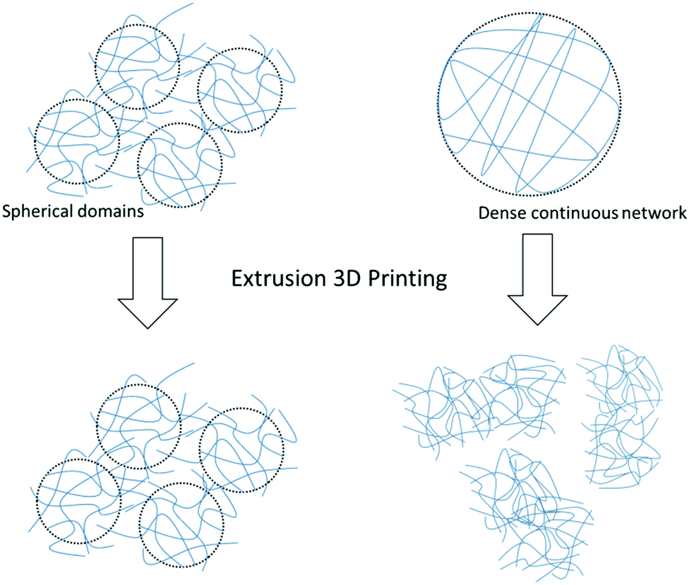 | ||
| Scheme 2 Schematic showing the recovery of spherical gel domains compared to a dense continuous network of fibres after extrusion. | ||
Conclusions
We have shown that solvent-triggered gels which form spherical domains composed of tightly packed primary fibres and fibrils can be printed effectively from a syringe. The gels can be 3D printed into an array of layered designs depending on the desired application. The quality of the prints of the solvent-triggered gels surpasses those made via a pH trigger, which instead contain a continuous smooth fibrous network before extrusion. We think these are substantial and transferable observations which have already been demonstrated across a range of gelators including several Fmoc derivatives gelled using different triggers. We have previously shown in detail how the microstructure can be strongly affected by the method of gel formation. The spherulitic microstructure needed can be achieved using a solvent-trigger to form the hydrogels. We have shown that this microstructure can be achieved for a range of LMWGs, and from a range of initial solvents including DMSO (as used here), ethanol, and hexafluoroisopropanol.30 It is also possible to vary the ratio of organic solvent to water in the final gel, and so we anticipate that it should be possible to prepare gels that can be printed with a range of properties. Importantly, the solvent-triggered gels with spherical domains were able to be 3D printed with good resolution to form a continuous fibrous network which showed superior recovery properties to those gels with different microstructures. We hope that these observations will be taken into consideration in the future when developing hydrogels for 3D printing and extrusion applications.Conflicts of interest
There are no conflicts to declare.Acknowledgements
We thank the EPSRC and the University of Liverpool for funding a DTA (MCN). DJA thanks the EPSRC for a Fellowship (EP/L021978/1). AMFC acknowledges an Erasmus traineeship. MB thanks UKRMP for funding (MR/K026739/1). BD thanks the EPSRC for funding (EP/L021978/1). The EPSRC are thanked for funding the confocal microscope used in this project (EP/J004790/1 and EP/N007417/1). ERC thanks the University of Glasgow for funding. MCN would also like to thank Emily Draper for helpful comments throughout the project. We thank Finlay Walton (University of Glagsow) for help setting up the confocal microscopy. We thank the STFC for funding our time at the ISIS facility (Experiment Number RB1710066). This work also utilized the BT-5 USANS instrument and facilities of the Center for High Resolution Neutron Scattering, supported in part by the National Science Foundation under Agreement No. DMR-1508249.50 This work benefitted from SasView software, originally developed by the DANSE project under NSF award DMR-0520547.51 SasView also contains code developed with funding from the EU Horizon 2020 programme under the SINE2020 project Grant No. 654000. Certain commercial equipment, instruments, or materials are identified in this paper to foster understanding. Such identification does not imply recommendation or endorsement by the National Institute of Standards and Technology, nor does it imply that the materials or equipment identified are necessarily the best available for the purpose.Notes and references
- J. L. Drury and D. J. Mooney, Biomaterials, 2003, 24, 4337–4351 CrossRef CAS PubMed.
- M. Rodrigues, A. C. Calpena, D. B. Amabilino, M. L. Garduño-Ramírez and L. Pérez-García, J. Mater. Chem. B, 2014, 2, 5419 RSC.
- S. Gupta, M. Singh, M. Amarendar Reddy, P. S. Yavvari, A. Srivastava and A. Bajaj, RSC Adv., 2016, 6, 19751–19757 RSC.
- K. J. Skilling, F. Citossi, T. D. Bradshaw, M. Ashford, B. Kellam and M. Marlow, Soft Matter, 2014, 10, 237–256 RSC.
- X. Li, Y. Wang, C. Yang, S. Shi, L. Jin, Z. Luo, J. Yu, Z. Zhang, Z. Yang and H. Chen, Nanoscale, 2014, 6, 14488–14494 RSC.
- Y. Zhou and X. Li, Chin. Chem. Lett., 2017, 28, 1835–1840 CrossRef CAS.
- T. Billiet, M. Vandenhaute, J. Schelfhout, S. Van Vlierberghe and P. Dubruel, Biomaterials, 2012, 33, 6020–6041 CrossRef CAS PubMed.
- S. V. Murphy, A. Skardal and A. Atala, J. Biomed. Mater. Res., 2013, 101 A, 272–284 CrossRef PubMed.
- T. Jungst, W. Smolan, K. Schacht, T. Scheibel and J. Groll, Chem. Rev., 2016, 116, 1496–1539 CrossRef CAS PubMed.
- A. Carlson, A. M. Bowen, Y. Huang, R. G. Nuzzo and J. A. Rogers, Adv. Mater., 2012, 24, 5284–5318 CrossRef CAS PubMed.
- S. Ji and M. Guvendiren, Front. Bioeng. Biotechnol., 2017, 5, 1–8 Search PubMed.
- T. J. Hinton, Q. Jallerat, R. N. Palchesko, J. H. Park, M. S. Grodzicki, H.-J. Shue, M. H. Ramadan, A. R. Hudson and A. W. Feinberg, Sci. Adv., 2015, 1, 1–10 Search PubMed.
- J. A. Reid, P. A. Mollica, G. D. Johnson, R. C. Ogle, R. D. Bruno and P. C. Sachs, Biofabrication, 2016, 8, 25017 CrossRef PubMed.
- K. Hölzl, S. Lin, L. Tytgat, S. Van Vlierberghe, L. Gu and A. Ovsianikov, Biofabrication, 2016, 8, 32002 CrossRef PubMed.
- L. Ouyang, C. B. Highley, C. B. Rodell, W. Sun and J. A. Burdick, ACS Biomater. Sci. Eng., 2016, 2, 1743–1751 CrossRef CAS.
- L. Ouyang, C. B. Highley, W. Sun and J. A. Burdick, Adv. Mater., 2017, 29, 1604983 CrossRef PubMed.
- L. Shi, H. Carstensen, K. Hölzl, M. Lunzer, H. Li, J. Hilborn, A. Ovsianikov and D. A. Ossipov, Chem. Mater., 2017, 29, 5816–5823 CrossRef CAS.
- L. C. Hsiao, A. Z. M. Badruddoza, L.-C. Cheng and P. S. Doyle, Soft Matter, 2017, 13, 921–929 RSC.
- C. B. Highley, C. B. Rodell and J. A. Burdick, Adv. Mater., 2015, 27, 5075–5079 CrossRef CAS PubMed.
- R. Suntornnond, J. An and C. K. Chua, Macromol. Mater. Eng., 2017, 302, 1600266 CrossRef.
- A. M. Pekkanen, R. J. Mondschein, C. B. Williams and T. E. Long, Biomacromolecules, 2017, 18, 2669–2687 CrossRef CAS PubMed.
- I. Donderwinkel, J. C. M. van Hest, N. R. Cameron, M. Duocastella, B. Pippenger, S. Bellance, R. Bareille, M. Remy, L. Bordenave, J. Amedee, F. Guillemot, P. Strippoli, S. Canaider, A. Tamayol, A. Khademhosseini, M. R. Dokmeci, A. Atala, A. Khademhosseini, G. H. Zhu, X. Y. Jin, S. R. Shin, M. R. Dokmeci and A. Khademhosseini, Polym. Chem., 2017, 31, 7250–7256 Search PubMed.
- J. P. Schneider, D. J. Pochan, B. Ozbas, K. Rajagopal, L. Pakstis and J. Kretsinger, J. Am. Chem. Soc., 2002, 124, 15030–15037 CrossRef CAS PubMed.
- C. Yan, A. Altunbas, T. Yucel, R. P. Nagarkar, J. P. Schneider and D. J. Pochan, Soft Matter, 2010, 6, 5143–5156 RSC.
- N. Zanna, S. Focaroli, A. Merlettini, L. Gentilucci, G. Teti, M. Falconi and C. Tomasini, ACS Omega, 2017, 2, 2374–2381 CrossRef CAS.
- X. Huang, S. R. Raghavan, P. Terech and R. G. Weiss, J. Am. Chem. Soc., 2006, 128, 15341–15352 CrossRef CAS PubMed.
- B. Raphael, T. Khalil, V. L. Workman, A. Smith, C. P. Brown, C. Streuli, A. Saiani and M. Domingos, Mater. Lett., 2017, 190, 103–106 CrossRef CAS.
- B. A. Aguado, W. Mulyasasmita, J. Su, K. J. Lampe and S. C. Heilshorn, Tissue Eng., Part A, 2012, 18, 806–815 CrossRef CAS PubMed.
- J. Raeburn, A. Zamith Cardoso and D. J. Adams, Chem. Soc. Rev., 2013, 42, 5143–5156 RSC.
- J. Raeburn, C. Mendoza-Cuenca, B. N. Cattoz, M. A. Little, A. E. Terry, A. Zamith Cardoso, P. C. Griffiths and D. J. Adams, Soft Matter, 2015, 11, 927–935 RSC.
- C. Colquhoun, E. R. Draper, R. Schweins, M. Marcello, D. Vadukul, L. C. Serpell and D. J. Adams, Soft Matter, 2017, 13, 1914–1919 RSC.
- F. Tantakitti, J. Boekhoven, X. Wang, R. V. Kazantsev, T. Yu, J. Li, E. Zhuang, R. Zandi, J. H. Ortony, C. J. Newcomb, L. C. Palmer, G. S. Shekhawat, M. O. de la Cruz, G. C. Schatz and S. I. Stupp, Nat. Mater., 2016, 15, 469–476 CrossRef CAS PubMed.
- J. Raeburn, G. Pont, L. Chen, Y. Cesbron, R. Lévy and D. J. Adams, Soft Matter, 2012, 8, 1168–1174 RSC.
- M. D. Segarra-Maset, V. J. Nebot, J. F. Miravet and B. Escuder, Chem. Soc. Rev., 2013, 42, 7086–7098 RSC.
- L. Chen, S. Revel, K. Morris, L. C. Serpell and D. J. Adams, Langmuir, 2010, 26, 13466–13471 CrossRef CAS PubMed.
- A. Mahler, M. Reches, M. Rechter, S. Cohen and E. Gazit, Adv. Mater., 2006, 18, 1365–1370 CrossRef CAS.
- N. A. Dudukovic and C. F. Zukoski, Langmuir, 2014, 30, 4493–4500 CrossRef CAS PubMed.
- D. J. Adams, M. F. Butler, W. J. Frith, M. Kirkland, L. Mullen and P. Sanderson, Soft Matter, 2009, 5, 1856–1862 RSC.
- Y. Pocker and E. Green, J. Am. Chem. Soc., 1973, 95, 113–119 CrossRef CAS PubMed.
- J. Gao, C. Tang, M. A. Elsawy, A. M. Smith, A. F. Miller and A. Saiani, Biomacromolecules, 2017, 18, 826–834 CrossRef CAS PubMed.
- R. Darby, Chemical Engineering and Fluid Mechanics, Marcel Dekker Inc., 1996 Search PubMed.
- D. J. Adams, L. M. Mullen, M. Berta, L. Chen and W. J. Frith, Soft Matter, 2010, 6, 1971–1980 RSC.
- S. Kyle, Z. M. Jessop, A. Al-Sabah and I. S. Whitaker, Adv. Healthcare Mater., 2017, 6, 1700264 CrossRef PubMed.
- L. Chen, J. Raeburn, S. Sutton, D. G. Spiller, J. Williams, J. S. Sharp, P. C. Griffiths, R. K. Heenan, S. M. King, A. Paul, S. Furzeland, D. Atkins and D. J. Adams, Soft Matter, 2011, 7, 9721–9727 RSC.
- K. L. Morris, L. Chen, J. Raeburn, O. R. Sellick, P. Cotanda, A. Paul, P. C. Griffiths, S. M. King, R. K. O’Reilly, L. C. Serpell and D. J. Adams, Nat. Commun., 2013, 4, 1480 CrossRef PubMed.
- A. Z. Cardoso, L. L. E. Mears, B. N. Cattoz, P. C. Griffiths, R. Schweins and D. J. Adams, Soft Matter, 2016, 12, 3612–3621 RSC.
- M. C. Nolan, J. J. Walsh, L. L. E. Mears, E. R. Draper, M. Wallace, M. Barrow, B. Dietrich, S. M. King, A. J. Cowan and D. J. Adams, J. Mater. Chem. A, 2017, 5, 7555–7563 CAS.
- M. A. Iannuzzi, R. Reber, D. M. Lentz, J. Zhao, L. Ma and R. C. Hedden, Polymer, 2010, 51, 2049–2056 CrossRef CAS.
- H. R. Ramay, M. C. Branco, P. Schneider and D. J. Pochan, Faraday Discuss., 2008, 139, 251–264 RSC.
- A. R. Drews, J. A. Barker, C. J. Glinka and M. Agamalian, Phys. B, 1998, 241–243, 189–191 Search PubMed.
- http://www.sasview.org .
Footnote |
| † Electronic supplementary information (ESI) available: Fig. S1–S16 and Tables S1, S2. Modification and configuration of the 3D printer; preparation of LMWG solutions and gels; experimental techniques; printing with shear rate dependence; fits of small angle neutron scattering data and ultra small angle neutron scattering data. Rheological strain and frequency sweeps; rheological compression sweeps. See DOI: 10.1039/c7sm01694h |
| This journal is © The Royal Society of Chemistry 2017 |