
 Open Access Article
 This Open Access Article is licensed under a
 Creative Commons Attribution 3.0 Unported Licence
Stratification in binary colloidal polymer films: experiment and simulations†
D. K.
Makepeace
a,
A.
Fortini
a,
A.
Markov
a,
P.
Locatelli
b,
C.
Lindsay
b,
S.
Moorhouse
b,
R.
Lind
b,
R. P.
Sear
 a and
J. L.
Keddie
*a
a and
J. L.
Keddie
*a
aDepartment of Physics, University of Surrey, Guildford, Surrey GU2 7XH, UK. E-mail: j.keddie@surrey.ac.uk
bSyngenta, Jealott's Hill International Research Centre, Bracknell, Berkshire RG42 6EY, UK
First published on 18th September 2017
Abstract
When films are deposited from mixtures of colloidal particles of two different sizes, a diverse range of functional structures can result. One structure of particular interest is a stratified film in which the top surface layer has a composition different than in the interior. Here, we explore the conditions under which a stratified layer of small particles develops spontaneously in a colloidal film that is cast from a binary mixture of small and large polymer particles that are suspended in water. A recent model, which considers the cross-interaction between the large and small particles (Zhou et al., Phys. Rev. Lett., 2017, 118, 108002), predicts that stratification will develop from dilute binary mixtures when the particle size ratio (α), initial volume fraction of small particles (ϕS), and Péclet number are high. In experiments and Langevin dynamics simulations, we systematically vary α and ϕS in both dilute and concentrated suspensions. We find that stratified films develop when ϕS is increased, which is in agreement with the model. In dilute suspensions, there is reasonable agreement between the experiments and the Zhou et al. model. In concentrated suspensions, stratification occurs in experiments only for the higher size ratio α = 7. Simulations using a high Péclet number, additionally find stratification with α = 2, when ϕS is high enough. Our results provide a quantitative understanding of the conditions under which stratified colloidal films assemble. Our research has relevance for the design of coatings with targeted optical and mechanical properties at their surface.
Colloidal particles can be cast from suspensions to make a coating or film on a substrate. Colloidal films have a wide variety of applications, including inks,1 cosmetics,2 pharmaceutical encapsulation,3,4 active ingredient binders,5,6 adhesives,7,8 and paints.9,10 Waterborne colloidal polymer particles, commonly known as latex, are attractive because they form dry films with only a small (or no) release of volatile organic compounds (VOCs) into the environment,11 whereas their solvent-cast analogues are polluting to the atmosphere.
Mixtures of more than one type of colloidal particle are of interest because they hold the potential to control and alter the properties of a final composite film. For example, the addition of hard polymer particles to soft polymer particles (with a glass transition temperature, Tg, below the temperature of use) decreases the tack of film surfaces, even when present at relatively low concentrations,12 increases the dynamic storage modulus significantly,13–15 but decreases the strain at failure.16
Binary colloidal suspensions in which the number ratio of large![[thin space (1/6-em)]](https://www.rsc.org/images/entities/char_2009.gif) :small particles is 1:1 or 2:1 etc. have been shown to create close-packed arrays, known as binary colloidal crystals (bCCs), which have structural similarities to the NaCl crystal structure.17 Depending on the size ratio and relative numbers of spherical polymer particles, a variety of crystal structures can be deposited.18,19 Computer simulations predict a huge variety of possible structures in these systems, some of which have been experimentally verified.20 There has been previous work using dilute binary colloidal polymer suspensions to deposit dried particle monolayers or multi-layers via dipping,18 horizontal deposition,21 and lifting from the air–water interface.22 However, there have been fewer systematic studies of particle ordering in structures deposited by horizontal drying from concentrated binary colloidal suspensions of similarly charged (nano)particles.
:small particles is 1:1 or 2:1 etc. have been shown to create close-packed arrays, known as binary colloidal crystals (bCCs), which have structural similarities to the NaCl crystal structure.17 Depending on the size ratio and relative numbers of spherical polymer particles, a variety of crystal structures can be deposited.18,19 Computer simulations predict a huge variety of possible structures in these systems, some of which have been experimentally verified.20 There has been previous work using dilute binary colloidal polymer suspensions to deposit dried particle monolayers or multi-layers via dipping,18 horizontal deposition,21 and lifting from the air–water interface.22 However, there have been fewer systematic studies of particle ordering in structures deposited by horizontal drying from concentrated binary colloidal suspensions of similarly charged (nano)particles.
Excellent progress has been made in understanding the phase equilibria of binary colloidal suspensions. However, when depositing films by the evaporation of the continuous phase, the colloidal suspension is not at equilibrium. Non-equilibrium behaviour is much less well understood but can be richer. In most film applications, the colloidal system is not at equilibrium. In this work, we consider the distribution of the two populations of particles in a binary colloidal film in which the particles are stratified in layers of particles with different size during the non-equilibrium process of drying.
Stratified films are desirable for many applications23–26 because they allow the top, bottom or bulk interior regions to have differing properties. Stratification of particles during drying will occur in a mixture of two (or more) types of particle when there are differences in their diffusivity. When the top surface of a wet film descends during evaporation, colloidal particles will accumulate near the liquid/air interface if their rate of diffusion is slow relative to evaporation.27 The relative rate of evaporation over diffusion is measured using a Péclet number, Pe.
According to the Stokes–Einstein equation, the diffusion coefficient for a colloidal particle in a fluid is inversely related to its size. Trueman et al.28,29 showed with modelling and experiments of mixtures of particles with two sizes that stratification by size developed at intermediate evaporation rates. In this regime, slow-diffusing large particles accumulate at the top air/water interface, but the faster-diffusing small particles are more uniformly distributed. This mechanism applies when Pe for the large particles, PeL, is greater than unity, but Pe for small particles, PeS, is less than unity. The simulations of Trueman et al. showed that stratification by size is inhibited at higher volume fractions of particles. Interactions between the particles30,31 can also result in the motion of the particles in a mixture. This motion is caused by gradients in the concentration of the mixture components and is called diffusiophoresis or cross-diffusion.
Fortini et al.32 recently discovered a stratification mechanism that relies on particle interactions, and is applicable at higher Pe when both large and small particles have large values of Pe. During the drying process, a gradient of the small particles pushes large particles away from the descending air/water interface faster than the smaller particles are pushed away. Their work used both simulations and experiments to consider stratification in a mixture of particles with a large:small size ratio, α, of 7. They found that stratification occurred only when the concentration of small particles in relation to large particles was sufficiently high. More recently, Fortini and Sear33 presented simulations of polydisperse colloids in which stratification by size occurs.
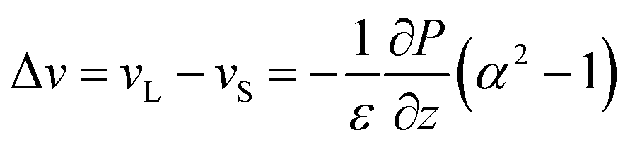
The simulations of Fortini et al.32 were consistent with a model in which the downward velocity of the large particles, vL, is greater than the velocity of the small particles, vS. According to their physical model, the difference in these velocities is related to the particle size ratio, α, as:
 | (1) |
Very recently, Zhou et al.35 presented a related model, which considers the interactions between the small and large particles. They used a second-virial coefficient theory that will be accurate in dilute suspensions. They derived an equation, applicable for a dilute binary mixture of particles, which defines the parameter space where stratification is expected. The boundary between stratified and non-stratified regimes was predicted to be:
| α2(1 + PeS)ϕS = 1 | (2) |
The computer simulations of Fortini et al.32 and Howard et al.34 employ very similar models. Howard et al. demonstrated that their results are consistent with the results of Fortini et al.32 Similarly, Zhou et al.35 specifically compared their predictions to the results of Fortini et al. and found general agreement. We note that Howard et al.34 found stratification in their simulations when PeS = 1.5, α = 8, and ϕS = 0.03, such that α2ϕS(1 + PeS) = 4.8 > 1, which predicts stratification according to the ZJD model (eqn (2)). Thus, there is some consistency between these two works.
This analysis suggests that although the ZJD model should only be valid for dilute suspensions, it at least predicts trends observed in simulations when the volume fractions are higher. The ZJD theory,35 our theory,32 the density functional theory of Howard et al.,34 and the simulation results agree that the interaction between the small and large particles drive the segregation by particle size. They also agree that stratification requires a gradient in the concentration of the small particles, which is only present for Péclet numbers greater than unity.
Martín-Fabiani et al.36 studied stratification in a binary system in which α had an initial value of 7. In their experiments, the radius of the small particles was increased, while the number of particles remained constant. Thus, α decreased at the same time that ϕS increased. They found no stratification when α was lower and ϕS was higher. They argued that with a higher ϕS there was less time available for stratification prior to reaching the point of particle jamming. Also, the differences in the velocity of the large and small particles was lower, according to eqn (1).
The ZJD model35 provides a useful framework to design colloidal systems to undergo stratification. However, their theory strictly applies to the dilute regime only. All three models (ZJD, Fortini et al.32 and Howard et al.34) use implicit solvents. To keep the computation fast and the theories simple, the solvent (water) is replaced by a uniform continuum, which exerts viscous drag and random Brownian forces on the colloidal particles in Langevin or Brownian dynamics simulations. There is a clear need to test these models, particularly when the initial particle concentration is high.
It has been shown previously via Monte Carlo simulations, in combination with experimental studies, that the disorder of particle packing increases with size polydispersity.37 It was also reported that increasing evaporation rate increases the disorder. Other experimental work has shown how small numbers of large particles can disrupt the local packing of small particles.38,39 In monosized latex films, hexagonal close-packing is commonly observed.40 It has been recognised in the literature that particles of a differing size disrupt the ordering, but a greater quantitative understanding of the phenomenon is needed.41
Randomly-packed colloidal structures have applications in disordered photonic materials to suppress the propagation of light.42 Random close-packed structures are also found in nature and give rise to structural colour.43 Disordered colloidal structures that scatter light at specific wavelengths and angular distributions hold potential to create colours in paints.44 Disordered structures of electron donor and acceptor particles have uses as bulk heterojunctions in photovoltaic applications.45 Despite this potential in applications and numerous advantages over ordered structures, disordered binary particle assemblies have been largely unexplored.41 There is a particular need to understand the relation between particle concentrations and particle ordering in binary colloidal films, and we address this topic here.
In this work, we examine whether stratification occurs in systems with one of two different size ratios: α = 2 and α = 7. We employ both experiments and Langevin dynamics simulations. First, we consider the dilute system and compare experimental results to the predictions of the ZJD diffusion model. Then, we examine stratification in a concentrated system in which the total initial volume fraction of particles is fixed at ϕtot = ϕS + ϕL = 0.4. Our experiments and simulations constitute the first systematic tests of the ZJD model. We provide a comprehensive set of data to build the understanding of stratification in colloidal films. We also examine quantitatively the development of disorder in binary colloidal films as the fraction of small particles is increased.
Experimental
Latex synthesis
Latices were prepared by emulsion polymerisation of methyl methacrylate (MMA), butyl acrylate (BA) and methacrylic acid (MAA) at Akzo Nobel Decorative R&D (Slough, UK). A monomer ratio of 18.3:13.3:1 of MMA:BA:MAA made a copolymer with a Tg of ca. 40 °C (determined by differential scanning calorimetry with a heating rate of 10 °C min−1 (TA Instruments, New Castle, DE, USA)). Two sizes of these ‘hard’ particles were synthesized (see Table 1). Through the same method, ‘soft’ particles were synthesised with a higher proportion of BA to yield a copolymer with a Tg of 12.9 °C. Synthesis of these particles is described in greater detail in a previous publication.46 The particle diameters and polydispersity index (PDI) were measured using dynamic light scattering (Malvern Zetasizer Nano Series, Malvern, UK).
| Particle name | Hydrodynamic diameter, dh (nm) | PDI | T g (°C) |
|---|---|---|---|
| LgSf | 378 | 0.069 | 12.9 |
| MedHd | 181 | 0.005 | 41.1 |
| SmHd | 54 | 0.242 | 33.6 |
Hard nanoparticles (with a hydrodynamic diameter of 54 nm) were prepared through emulsion polymerisation of MMA, BA and MAA. A description of the synthesis is provided elsewhere.8 For the purposes of this work, the particles will be named according to their relative diameter (large (Lg), medium (Med), small (Sm)) and type (hard (Hd) of soft (Sf)), i.e. ‘LgHd’ denotes ‘large hard’ particles. Table 1 summarises the types of particles.
Mixtures of soft and hard particles were made by mixing the dispersions of the particles listed in Table 1. They are named according to their nominal size ratio of large to small particles (α). Compositions with a range of volume fractions of small particles, ϕS, and large particles, ϕL, were made. Table 2 lists the initial volume fraction of the mixtures used in experiments. In the first series of experiments, the suspensions were dilute; ϕL was fixed at 0.05 and ϕS was always below 0.1. In the second series of experiments, the suspensions were concentrated with the total initial volume concentration, ϕtot, set to 0.4.
| α | Composition | ϕ S | ϕ L |
|---|---|---|---|
| 2 | LgSf + MedHd (dilute) | 0.004, 0.02, 0.05, 0.08 | 0.05 |
| 2 | LgSf + MedHd (concentrated) | 0.004, 0.01, 0.02, 0.04, 0.08, 0.12, 0.16, 0.2 | 0.4 − ϕS |
| 7 | LgSf + SmHd (dilute) | 0.004, 0.02, 0.05, 0.08 | 0.05 |
| 7 | LgSf + SmHd (concentrated) | 0.02, 0.04, 0.08, 0.12, 0.16, 0.2 | 0.4 − ϕS |
Film formation
Glass substrates (18 mm × 18 mm) were cleaned in acetone in a sonicating bath for 5 min. They were dried using nitrogen gas and placed in a UV ozone cleaner (Bioforce, Nanosciences) for 5 min to produce a hydrophilic surface. The volume fraction of particles in the initial dispersion was reduced, as needed, by dilution with deionised water. Films were cast by depositing 0.05 mL from a pipette onto the substrate and then spreading to coat the entire surface area. When ϕtot = 0.4, the initial thickness of the films was estimated to be H = 0.16 mm. Films were formed in static air at a room temperature of approximately 22 °C and relative humidity of 50%. Under these conditions, the evaporation rate, E, of water in a latex film has been reported to be 1.1 × 10⁻⁷ m s−1 (expressed as the velocity of the falling surface),47 and this is taken as the value in our calculations that follow.Image analysis
Images of the surface of each of the surfaces of each of the cast films were obtained using an atomic force microscope (NTEGRA, NT-MDT) and analysed using NT-MDT Nova software. An NT-MDT Au-coated cantilever with a nominal spring constant of 0.5 N m−1 was used. Images were obtained using intermittent contact over areas of 5 μm × 5 μm and 2.5 μm × 2.5 μm for qualitative analysis and over areas of 5 μm × 5 μm for quantitative analysis of the surface ordering.Order parameters
In the present work, the coordinates were determined for the LgSf particles (and LgHd) in 5 μm × 5 μm AFM images using ImageJ software (version 1.49), from the United States National Institute of Health (http://imagej.nih.gov). A custom macro script was used to generate the coordinates of the particles in the images. Any mistakes, such as missed particles or inaccurate selection of a particle, were corrected manually.The local symmetry of the particles was calculated using a two-dimensional version48 of the q6 orientation bond order parameter.49 The type of local symmetry of a particle is determined by looking at the distance between, and the orientations of, the neighbouring particles. More information is provided in the ESI.† Here, we distinguish between disordered particles and particles with hexagonal or square ordering. An example of the analysis is presented in Fig. 1.
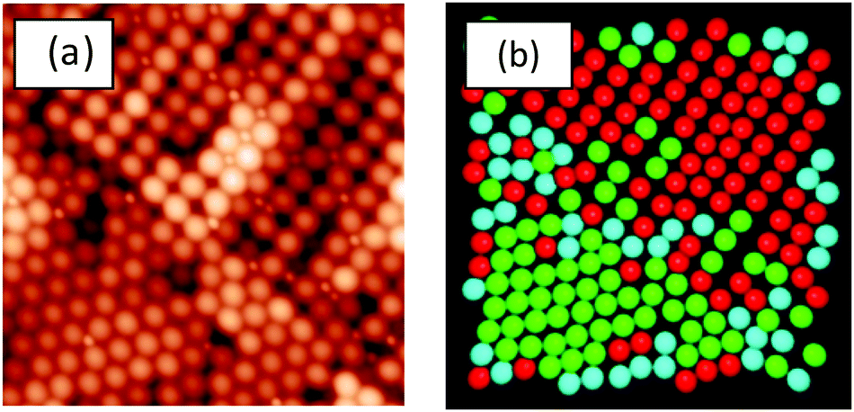 | ||
| Fig. 1 (a) AFM topographic image obtained from a binary film for which α = 2 and ϕS = 0.025. The image shows hexagonally-ordered, square-ordered, and disordered particles. Image area is 5 μm × 5 μm. (b) Image analysis highlights the different local ordering of individual particles in image (a). Green = hexagonal, red = square, and blue = disordered. | ||
Langevin dynamics simulations
We simulated a binary mixture of smaller and larger spherical purely repulsive particles with diameters of dS and dL, respectively. The simulation box has dimensions of Lx × Lv × H, where H is the height. We used periodic boundary conditions in the x- and y-directions, while in the z-direction the box is delimited at the bottom by a hard substrate, and at the top by a soft wall, which models the air–water interface. The particles are modelled as hydrophilic, with a contact angle with respect to the model interface equal to zero, which means that the particles are hydrophilic and not surface-active. We do not explicitly simulate the water molecules in which the particles are suspended, and describe the motion of the colloidal particles using an overdamped Langevin dynamics at constant temperature, T. The simulations were carried out using the LAMMPS package.50 Evaporation is modelled by the downward movement of the model air–water interface at constant velocity vev = 0.2dS/t0, with t0 being the unit of time used by LAMMPS.Our LAMMPS simulations use Langevin dynamics to model diffusing (i.e., Brownian) particles. In the simulations, we set the thermal velocities and drag coefficients of the particles to reproduce diffusive dynamics (on length scales of the particle diameters and above) with defined diffusion constants. These diffusion coefficients obey the Stokes–Einstein relation in the sense that they scale as one over the particle diameter. Details of the parameter values and how the diffusion constants are calculated have been reported previously.33 The initial volume fractions of our simulation runs are reported in Table S1 of the ESI.† We simulated two different size ratios: α = 2 and α = 7.
Data from the LAMMPS output file was analysed using a Python3 program. To compare with experiments on dried colloidal films, we used the configuration with a volume fraction nearest 0.64. The exact volume fractions are given in Table S1 in the ESI.† We choose the value of 0.64 because hard spheres jam at volume fractions around this value.51 It was observed that the pressure rose sharply at later times in the simulations, which reveals that the particles were being compressed. Concentration profiles were constructed in the top layer through a depth of 20dS with a bin width set to 1dS. It was found that bin widths of 0.5dS and 2dS gave similar profiles.
Scanning electron microscopy (SEM)
SEM images were obtained using a JEOL JSM-7100F electron microscope. Before imaging, samples were sputter coated with a 2 nm layer of Au. For cross-sectional imaging, films were submerged in liquid nitrogen until frozen then snapped using plastic tweezers. Images were obtained using an accelerating voltage of either 5 or 10 kV.Results and discussion
We will first review the experimental results for films made from suspensions that were initially dilute. We use AFM analysis to determine if a greater number of small particles is found at the top surface than is expected from a random mixture. An excess of small particles is taken as a signature of stratification. After exploring the dilute regime, we next present experimental results and simulations for films deposited from concentrated suspensions.Dilute regime
We start by presenting the surface structures of films in which ϕL was fixed at 0.05 and ϕS was varied. AFM images were obtained from the surfaces of films cast from mixtures with α = 2 and α = 7. The small, hard particles do not deform during film formation, and hence they protrude from the film surface, making them apparent in the AFM topographic images. Representative images obtained with both size ratios, with ϕS increasing from 0.004 to 0.08, are presented in Fig. 2.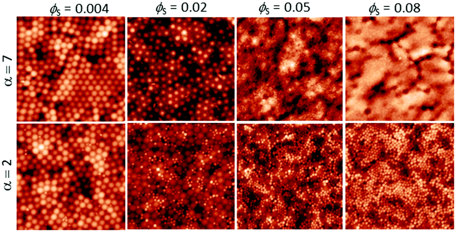 | ||
| Fig. 2 AFM height images obtained from binary blend films for which ϕL = 0.05 (dilute regime). α is shown before each row. ϕS is varied (as stated for each column). All image sizes are 5 μm × 5 μm. | ||
When the initial volume fraction of small particles is low (ϕS = 0.004) there are ordered regions of large particles at the film surface, in experiments with both size ratios. Only a few small particles can be seen. In contrast, when ϕS = 0.08 the surfaces are nearly fully covered with small particles. It is apparent that an increase in the number of small particles has a pronounced effect on the surface structure.
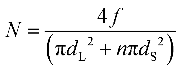
To test whether there is an excess of small particles at the interface we compared the surface compositions with a model that assumes that the particles are randomly mixed. For the situation in which there are n small particles (with a diameter of dS) per every large particle (diameter of dL), the number of large particles per unit area, N, is given via a simple geometric model as:
 | (3) |
Particles were counted in AFM images manually. Particles with their areas being 50% or more visible contributed to the count total; those less than 50% visible by eye were not counted. An experimental result in which the number of large particles per unit area is lower than the simple theoretical prediction indicates that stratification of small particles has occurred at the top of a film.
Fig. 3 shows the number density of large particles at the film surfaces determined experimentally compared with the geometric model assuming random mixing (given by eqn (3)) for both size ratios as ϕS is increased. The figure shows for the lowest value of ϕS (0.004) that the number of large particles at the film surface is consistent with the predictions of the model. However, for the highest ϕS (0.05 and 0.08), the number of large particles falls toward zero and is much lower than predicted by the model. This analysis indicates that stratification of the small particles in a layer at the top of the film has occurred. For the intermediate concentration, ϕS = 0.02, the number density of large particles is approximately one-half what is expected from the model, which we consider to be partial stratification.
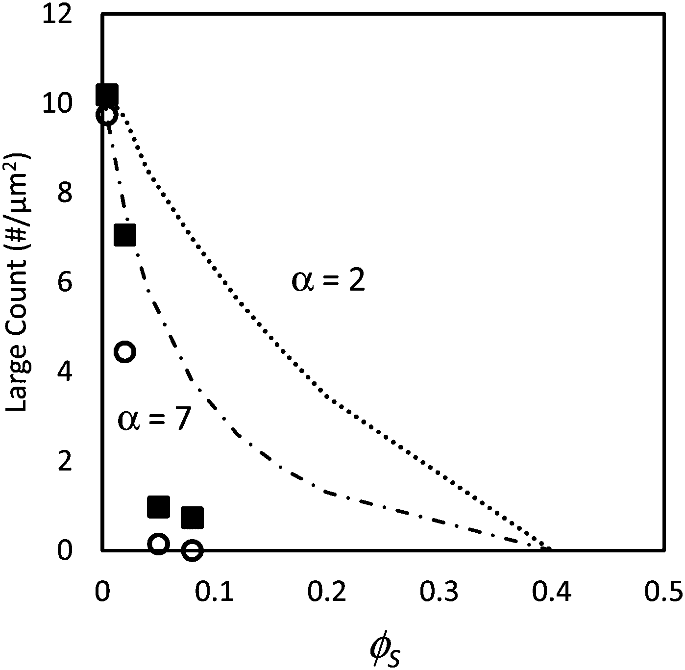 | ||
| Fig. 3 Counts of large particles per unit area, N, in experiments using particle mixtures with α = 2 (filled squares) and α = 7 (open circles) as a function of the volume fraction of small particles, ϕS. In all experiments, ϕL = 0.05 (dilute regime). Dotted line (α = 2) and dashed line (α = 7) show results from the simple geometric model given in eqn (3). | ||
Next, these experimental results are compared to the predictions of the ZJD model. For each experiment, α and ϕS are known. For the small particles, PeS is defined as:
 | (4) |
Following on from the simple analysis present in Fig. 3, each of the surface structures of the samples was classified as being either (1) stratified, (2) non-stratified, or (3) intermediate. The stratification of the binary colloidal films are represented in relation to the ZJD model by the symbols in Fig. 4. The region above and to the right of the solid line presenting eqn (2) is where stratification is predicted. At ϕS = 0.004, the films are not stratified in experiments, as is expected from the theory. At ϕS = 0.05 and ϕS = 0.08, the films are stratified, which is also consistent with the theory. At the intermediate composition of ϕS = 0.02, there is an intermediate amount of stratification, and the two data points straddle the line separating the stratified and non-stratified regions.
 | ||
| Fig. 4 Experimental data points (obtained using AFM analysis) in comparison to the prediction of eqn (2) (solid line). In all experiments, ϕL = 0.05 (dilute regime). Red open symbols designate stratified films according to analysis of the film surface, and filled blue symbols designate non-stratified. The two-colour symbol represents the intermediate situation. Results are presented for blends with two different size ratios: α = 2 (squares) and α = 7 (circles). According to ZJD model, the parameters above the line should be stratified. | ||
A clear weakness in our experimental AFM analysis is that we only consider the surface structure here, and we do not obtain depth profiles of particle concentrations. The theory defines the stratified state as having a decreasing concentration of large particles going toward the surface (a negative concentration gradient). Without sub-surface information, the stratification cannot be fully characterised.
Concentrated regime: low ϕS
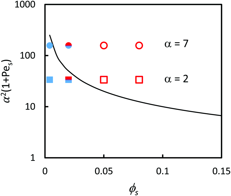
Colloidal films used in a variety of applications are often deposited from a concentrated dispersion, rather a dilute system.7–16 Therefore, stratification in concentrated dispersions is of great practical interest, and hence we consider it next. We present experiments and simulations in which ϕtot is fixed at 0.4, as ϕS and ϕL are varied.Fig. 5 and 6 presents a series of AFM images of the surfaces of colloidal films as ϕS was increased with α = 2 and α = 7, respectively. In conjunction with the experimental results, Langevin dynamics simulations were also conducted. From these simulations, the final snapshot of the top surface of the film was captured. The surfaces are shown and compared to their respective experimental results for α = 2 (Fig. 5) and α = 7 (Fig. 6).
 | ||
| Fig. 5 Images of the top surfaces of films obtained from Langevin dynamics simulations (upper row) and AFM topography (bottom row). For all images, α = 2 and the initial volume fraction of particles, ϕtot, is 0.4. The initial volume fraction of small particles, ϕS is shown in the label for each image. The area of each image is 5 μm × 5 μm. Particle colours in the simulations indicate a particular particle's ordering parameter: hexagonal (green), square (red), or disordered (blue). The order parameters for small particles (in yellow) were not found. | ||
 | ||
| Fig. 6 Images of the top surfaces of films obtained from Langevin dynamics simulations (upper row) and AFM topography (bottom row). For all image, α = 7 and the initial volume fraction of particles, ϕtot, is 0.4. The volume fraction of small particles, ϕS, is shown in the box for each image. The area of each image is 2.5 μm × 2.5 μm. Particle colours in the simulations indicate each particle's order parameter: hexagonal (green), square (red), disordered (blue). The ordering parameter for small particles (in yellow) was not calculated. | ||
When α = 2, as ϕS is increased, both experiments and simulations show less hexagonal ordering of particles. This can be seen qualitatively through a visual comparison of simulation snapshots and experimental AFM images in Fig. 5. This general agreement illustrates that the structure formation in the colloidal films observed experimentally can be adequately described by simulations of repulsive Brownian particles without any trapping of particles at the air/water interface.
Quantitative analysis of ordering also shows very similar trends in the hexagonal ordering up to ϕS = 0.04. Comparisons of the experiments and simulations are shown in the ESI† in Fig. S1. Both the experimental and simulation data indicate a decrease in the hexagonal fraction by ca. 0.6 over this range. Above ϕS = 0.04, the simulations show a greater decrease in hexagonal ordering relative to the experimental results. The disorder in simulations also correlates with the experimental results up to ϕS = 0.002; both sets of data show an increase of ca. 0.30. Above ϕS = 0.002, the quantitative disorder shows a significant increase relative to the experimental results, as is discussed in the ESI.†
When α = 7 (Fig. 6), both the experiments and the simulations show the same trends of increasing disorder and a reduction in hexagonal order as ϕS is increased. Despite showing the same general trends, the values of ϕS at which hexagonal ordering is low (i.e. disorder is increased) are significantly lower for the simulation results. Simulations show a rapid decrease in hexagonal ordering, dropping to 0.00 at ϕS = 0.04 and a corresponding disorder of 1, whereas experimental results show significant hexagonal ordering of 0.83 at ϕS = 0.04. In this system, the presence of small particles stratified at the surface has an even greater impact on ordering results as significant stratification occurs in simulations at values as low as ϕS = 0.04.
Concentrated regime: high ϕS
We next consider films cast from suspensions that start with a total volume fraction of 0.4. A series of AFM images of the top surface of films with ϕS ranging from 0.12 to 0.2 is shown in Fig. 7 for both size ratios. We can see that stratification occurs for α = 7 when ϕS > 0.12, where there are very few large particles at the surface; it is nearly saturated with small particles. For α = 2, it is not clear from a simple visual observation whether stratification has occurred.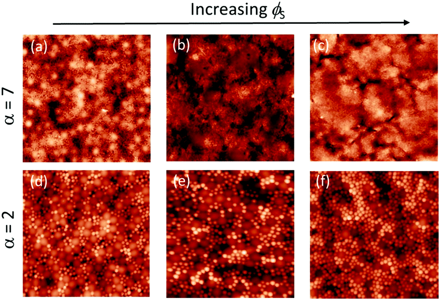 | ||
| Fig. 7 AFM height images of binary blend films for which α = 7 (a–c), and α = 2 (d–f). The initial volume fraction of particles, ϕtot = 0.4 (concentrated regime). Three volume fractions of small particles, ϕS were used: (a), (d) ϕS = 0.12; (b), (e) ϕS = 0.16; and (c), (f) ϕS = 0.2. All images are 5 μm × 5 μm in area. | ||
When α = 7, the quantitative measurements of large number density, presented in Fig. 8, also show that stratification occurs when ϕS ≥ 0.12. It is seen that the number of particles per unit area is significantly lower than in the theoretical model that assumes random mixing. When α = 2, the experimental results shown in Fig. 8 are very similar to the geometric model predictions, indicating that stratification has not occurred.
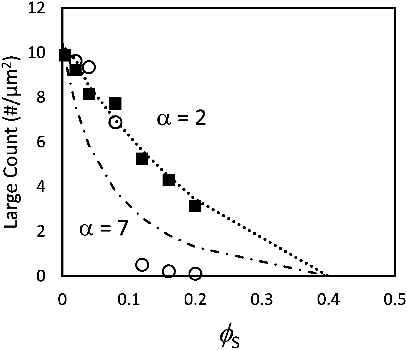 | ||
| Fig. 8 Counts of large particles per unit area in experiments using particle blends with α = 2 (filled squares) and α = 7 (open circles). The dotted line (α = 2) and dashed line (α = 7) show results from the simple geometric model given in eqn (3). In these experiments, the initial total volume fraction of particles, ϕtot, was 0.4. | ||
Both the ZJD model35 and the model of Fortini et al.32 predict that at a fixed initial volume fraction of the small particles, stratification is stronger for larger values of α. We observe that the trend in our experiments matches the model's predicted trend. The ZJD prediction in eqn (2) defines a threshold, above which the gradient in the concentration of small particles becomes large enough to push the large particles away from the top surface. It appears that for α = 2, and with a high initial volume fraction, the gradients of the small particles during drying never become large enough to deplete the large particles from the top surface. Note that our particle concentrations start at a volume fraction of 0.40 but presumably jam as the volume fractions approach random packing51 at 0.64. Thus, the film height reduces by only about one third before particle mobility and hence stratification ceases.
The experimental results are compared to the predictions of the ZJD model (eqn (2)) in Fig. 9. The theory predicts that all samples should show stratification at α = 7, whereas only three samples with the highest ϕS exhibit stratification in the experiments. At α = 2, the theory predicts stratification when ϕS is high, but there is no stratification in the experiments. The diffusion model was derived for dilute concentrations, and hence it is not surprising that it over-estimates stratification when compared with experiments on concentrated suspensions.
 | ||
| Fig. 9 (a) Experimental data points (obtained using AFM analysis) in comparison to the prediction of eqn (3) (solid line) in the concentrated regime where ϕtot = 0.4 (concentrated regime). The red open symbols designate stratified films according to analysis of the film surface, and filled blue symbols designate non-stratified films. Results are presented for blends with two different size ratios: α = 2 (squares) and α = 7 (circles). According to the predictions of the ZJD model, the parameters above the line should be stratified. | ||
We performed a similar analysis of the results of the simulations, such as those shown in Fig. 5 and 6, by counting the numbers of large particles per unit area at the film surfaces. The results are presented in Fig. S2 (ESI†). The simulated surfaces were analysed when the particles had reached the point of close packing. The specific arrangement of particles of the surface depends strongly on the applied pressure at the time when the simulation is analysed. The results in Fig. S2 (ESI†) show that there are fewer numbers of large particles being counted at the surface (with less than one-half their area being covered by small particles) than are predicted from random mixing. However, the Langevin dynamics simulations contain information on the positions of the particles throughout the film thickness during the drying process. Hence, they can be used to determine stratification through measurements of particle concentration gradients in the z direction, normal to the substrate. This method to analyse the stratification in the simulations is more reliable than counting large particles at the surface and hence is used hereafter.
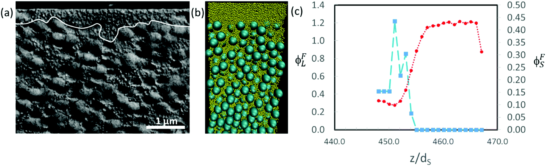
Fig. 10c presents a plot of how the final concentrations of small and large particles, ϕFS and ϕFL, respectively, vary at and just below the top surface. The final concentration was obtained from the data set in which the total volume fraction of particles was approximately 0.64, which corresponds to the point of random packing.51Fig. 10b shows a cross-sectional view of a simulation for α = 2 and ϕS = 0.19.
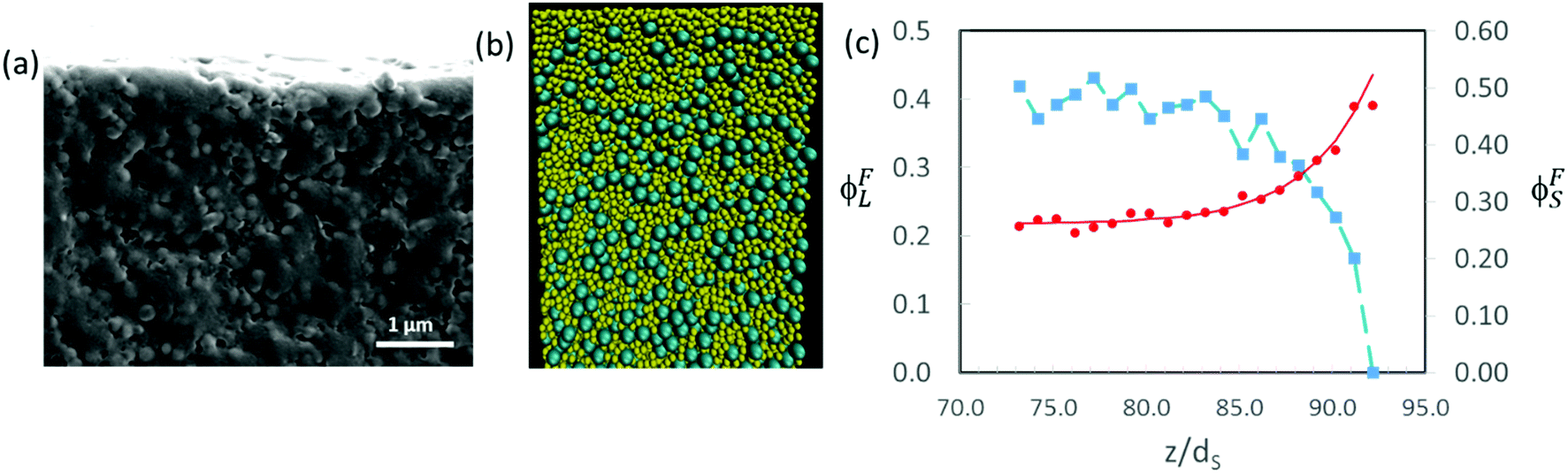 | ||
| Fig. 10 (a) SEM image of cryo-fractured cross-sections of dried films for which α = 2, ϕS = 0.2 and ϕtot = 0.4. Scale bar is 1 μm. There is no apparent stratification of the film. (b) Cross-sectional visualisation of the results of a Langevin dynamics simulations for which α = 2, ϕS = 0.16 and ϕtot = 0.4. The small particles are shown in yellow. (c) Particle concentration profiles near the top surface for the simulation in (b). The distance in the vertical direction, z, is expressed in units of the small particle diameter, dS. The red circles show ϕFS for the small particles, and the blue squares show ϕFL for the large particles. The characteristic width of the profile is w = 4.2dS. | ||
The concentration profiles in Fig. 10c show almost complete depletion of large particles at the top surface and an excess of small particles there. The negative concentration gradient of large particles indicates stratification according to the definition of Zhou et al.35 Note however that the depletion is only over a few particle diameters at the surface. This is different from the thick layers of solely small particles observed by Fortini et al.32 in their simulation studies, which all started at the lower volume fraction of 0.1. We estimate the width of the stratified layer, w, by fitting an equation of the form:
 | (5) |
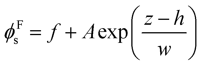
In experiments, the extent of stratification can be investigated qualitatively in SEM images of cryo-fractured cross-sections. When α = 2 and ϕS = 0.2, there is no clear evidence for stratification (Fig. 10a). The cross-sectional structure appears similar near the top and bottom of the film. Quantitative analysis of the cross-sections is not reliable because of difficulty in distinguishing large and small particles in the SEM images. Pull-out and fracture of particles creates additional uncertainty, making the method unreliable.
In Fig. 11, we show similar analysis for colloidal mixtures with a higher size ratio of α = 7. For experiments with ϕS = 0.2, a distinct layer of small particles is seen to lie above a layer containing large particles (Fig. 11a). The thickness of the stratified layer is not uniform, but in some regions it is approximately the thickness of two large particles (ca. 700 nm). As was also concluded when observing the top surface of the film, there is stratification. In the Langevin dynamics simulation for this same size ratio, but with ϕS = 0.044, there is a similar distinct layer of small particles at the top of the film, with a thickness on the order of two large particle diameters (Fig. 11b and c). Similar layers can be seen in simulation and experiment, although at a lower ϕS in the simulation. The computer simulations use a simple approximate model that appears to over-predict stratification.
 | ||
| Fig. 11 (a) SEM image of cryo-fractured cross-sections of dried films for which α = 7, ϕS = 0.2 and ϕtot = 0.4. Scale bar is 1 μm. The white line demarcates the boundary of the stratified layer of small particles. (b) Cross-sectional visualisation of the results of a Langevin dynamics simulations for which α = 7, ϕS = 0.044 and ϕtot = 0.4. The small particles are shown in yellow. (c) Particle concentration profiles near the top surface for the simulation in (b). The distance in the vertical direction, z, is expressed in units of the small particle diameter, dS. The red circles show ϕFS for the small particles, and the blue squares show ϕFL for the large particles. | ||
Other simulation results in Fig. 12 show a variety in the extent of stratification. For mixtures with α = 2, Fig. 12a presents the profiles when ϕS = 0.02, whereas Fig. 12b presents the profiles for a higher ϕS of 0.12. At the lower ϕS, there is no enrichment below the surface, and no depletion of the large particles, but when ϕS is increased, an enriched layer of small particles develops. As we expect, upon increasing ϕS, there is a transition from no stratification (Fig. 12a), to a weak stratification (Fig. 12b), and finally to a thick stratified layer of the small particles (Fig. 10c).
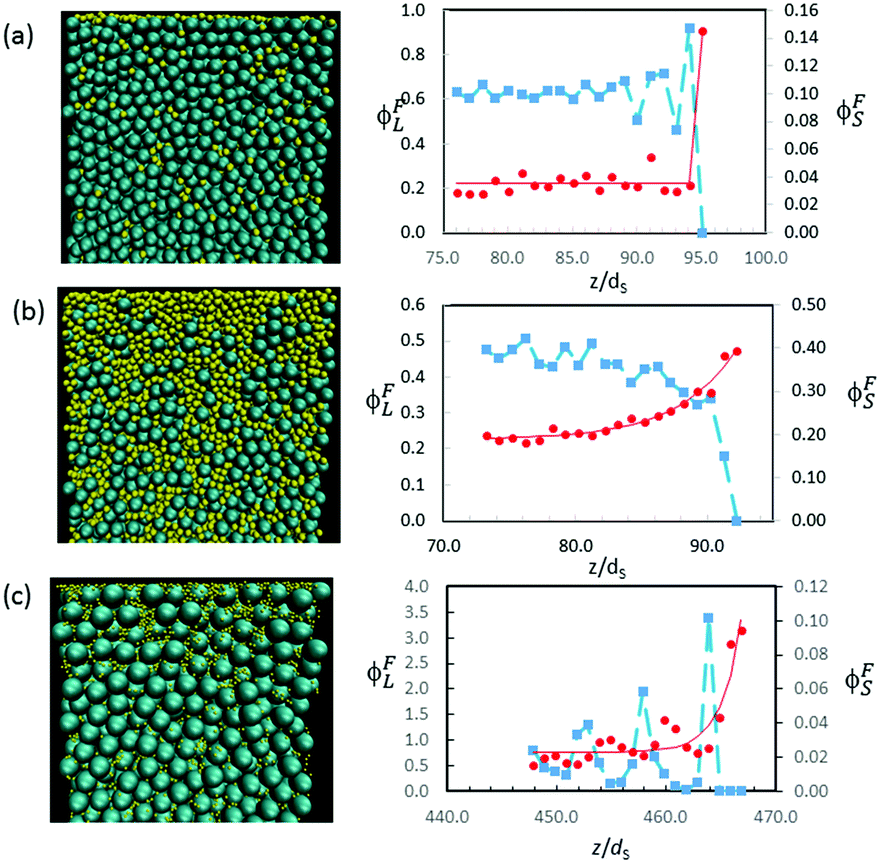 | ||
| Fig. 12 Cross-sectional visualisations (left column) and concentration profiles (right column) obtained from Langevin dynamics simulations of three different colloidal films, all with ϕtot = 0.4. The red circles show ϕFS, and the blue squares show ϕFL. (a) α = 2 and ϕS = 0.02. There is no evidence for stratification. (b) α = 2 and ϕS = 0.12. The characteristic width of the ϕFS profile (red line) is 4.5dS. (c) α = 7 and ϕS = 0.005. The characteristic width of the ϕFS profile (red line) is 1.9dS. | ||
Similarly, with α = 7, small particles partially decorate the film surface when ϕS is low (0.005), but there is no depletion of large particles near the surface (Fig. 12c). The width of the surface layer of small particles is only w = 1.9dS, which is less than one large particle diameter.
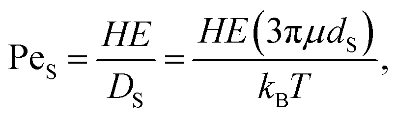
We compared the results of the simulations at high initial particle concentrations (ϕtot = 0.4) to the predictions of the ZJD model. To be consistent with the theory, we define stratification as having a negative concentration gradient of large particles at the film surface. We consider only concentration gradients extending over distances greater than at least one large particle diameter. We present the results of the comparison in Fig. 13.
 | ||
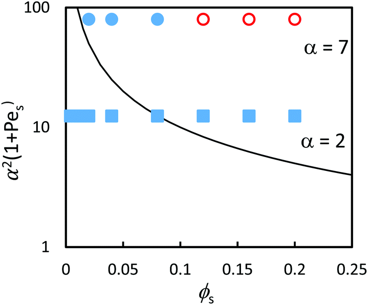
| Fig. 13 Data points obtained through analysis of the Langevin dynamics simulations and experiments in comparison to the prediction of eqn (3) (solid line) in the concentrated regime where ϕtot = 0.4. The red/pink open symbols designate stratified films according to the analysis, and filled blue symbols designate non-stratified films. Results are presented for blends with two different size ratios: α = 2 (squares) and α = 7 (circles). Experimental results presented previously in Fig. 9 are shown as pink and light blue; simulations results are in red and dark blue. According to the ZJD model, the systems with parameter values above the solid line are expected to be stratified. The dashed grey line represents the approximate boundary that is observed between the stratified and non-stratified regions in experiments and simulations. | ||
The simulations find that stratification occurs in concentrated suspensions for the highest concentrations of small particles, as is expected from the theory. However, the boundary between the stratified and non-stratified regions is found at a higher ϕS than expected from the theory. Experimental results (presented previously in Fig. 9) are overlaid for comparison. The experiments and simulations used different values for PeS. Nevertheless, Fig. 13 reveals that stratification is observed for both simulations and experiment when α2(1 + PeS) has a value on the order of 100 and when ϕS is greater than 0.1. The dashed line in Fig. 13 represents an approximate boundary between the stratified and non-stratified regions. The boundary predicted by the ZJD model appears at lower values of the parameters, and hence the model appears to over-predict stratification in concentrated suspensions.
Conclusions
We have completed the first experimental test of the stratification theory of Zhou et al.35 We have found quantitatively the range of parameters for which stratification is (and is not) obtained. Our experiments and our simulations both find stratification of small particles in a surface layer during film formation. In dilute suspensions, with ϕL = 0.05, the stratification observed in experiments is broadly consistent with the predictions of the ZJD model. In concentrated suspensions, however, stratification is observed in both experiments and in simulations only when α = 7 and when ϕS is sufficiently high.We found that the parameters that are predicted by the ZJD model to lead to stratification do not always have this effect in the experiments and simulations for concentrated systems. However, the ZJD model makes several approximations, one of which is only valid at low particle concentrations. Hence, the model is not strictly applicable to concentrated systems. The comparison between the results of experiments and simulations for concentrated systems in Fig. 13 shows good agreement between the two where there is overlap in the parameter space. The simulations considered values of PeS that are higher than used in the experiments. As such, the simulation results can be compared to the predictions of the theory in parameter space that was not accessed experimentally. The simulations find stratification for α = 7 when PeS and ϕS are large. Looking at Fig. 13, the boundary between the stratified and non-stratified regions for both the experiments and simulations appears at values of α2ϕS(1 + PeS) higher than what is predicted by the ZJD theory.
The simulations for α = 2 show stratification when ϕS is greater than 0.1. However, stratification is not observed for α = 2 in any of the experiments. Thus, it appears that the model employed in our computer simulations has some limitations. The assumption of an implicit solvent and the consequent neglect of water flow during drying may be causing the simulations to over-predict stratification. We hope that our experiments will inspire future modelling work to overcome these limitations.
We can confirm that the ZJD model, as supported with our data, enables the prediction of how to make either thick or thin stratified surface layers or vertically uniform coatings from dilute suspensions. For example, using Fig. 4, and taking α = 3.5 as an example, we predict that there will be weak stratification in a suspension with approximately 2 vol% small particles. When there is 5 vol% small particles, we predict that a distinct layer of mainly small particles will be found at the surface. If stratification is undesirable, then it can be avoided with a low particle size ratio (such as α = 2) and with relatively low volume fractions of small particles (ϕS < 0.1). Furthermore, to suppress stratification, the Péclet number could be reduced by reducing the evaporation rate or the initial film thickness.
This work highlights the need to control the size ratio and volume concentration of particles when making films from colloidal suspensions, using the horizontal deposition method. We have identified the importance of the particle size ratio and the concentration of small particles when aiming to create or to avoid stratified layers. Our data will allow other researchers to engineer stratified coatings in a quantitative way, such as in the manufacture of scratch-resistant coatings from binary blends of hard and soft particles.52 Additionally, the results highlight the effects of stratification in disrupting the formation of binary colloidal crystals at film surfaces in a horizontal drying process, which has relevance to optical properties.43,44
Conflicts of interest
There are no conflicts to declare.Acknowledgements
We gratefully acknowledge support with AFM analysis from Dr I. Martín-Fabiani (now at Loughborough University) and general laboratory support from Violeta Doukova (University of Surrey). Funding for DKM's studentship was provided by Syngenta. Funding for AF was provided by the European Union Seventh Framework Programme BARRIER-PLUS project (FP7-SME-2012-2, No. 304758). Funding for AM was provided by the EPSRC Impact Acceleration Account at the University of Surrey (Reference: EP/K503939/1).References
- E. Tekin, P. J. Smith and U. S. Schubert, Soft Matter, 2008, 4, 703 RSC.
- S. A. Wissing and R. H. Müller, Int. J. Cosmet. Sci., 2001, 23, 233 CrossRef CAS PubMed.
- S. Obara and J. W. McGinity, Int. J. Pharm., 1995, 1, 126 Search PubMed.
- F. Lecomte, J. Siepmann, M. Walther, R. J. MacRae and R. Bodmeier, Pharm. Res., 2004, 21, 882 CrossRef CAS.
- P. Mulqueen, Adv. Colloid Interface Sci., 2003, 106, 83 CrossRef CAS PubMed.
- M. A. Faers and R. Pontzen, Pest Manage. Sci., 2008, 64, 820 CrossRef CAS PubMed.
- F. Deplace, C. Carelli, S. Mariot, H. Retzos, A. Chateauminois, K. Ouzineb and C. Creton, J. Adhes., 2009, 85, 18 CrossRef CAS.
- R. S. Gurney, D. Dupin, E. Siband, K. Ouzineb and J. L. Keddie, ACS Appl. Mater. Interfaces, 2013, 5, 2137 CAS.
- H. M. van der Kooij and J. Sprakel, Soft Matter, 2015, 11, 6353 RSC.
- S. Deniz, M. Arca, M. S. Eroglu and E. Arca, Prog. Org. Coat., 2016, 98, 14 CrossRef CAS.
- J. C. S. Chang, B. A. Tichenor, Z. Guo and A. Krebs, Indoor Air, 1997, 7, 241 CAS.
- S. T. Eckersley and B. J. Helmer, J. Coat. Technol., 1997, 69, 97 CrossRef CAS.
- J. Feng, M. A. Winnik, R. R. Shivers and B. Clubb, Macromolecules, 1995, 28, 7671 CrossRef CAS.
- J. Feng and M. A. Winnik, Macromolecules, 1997, 30, 4324 CrossRef CAS.
- J. Feng, E. Odrobina and M. A. Winnik, Macromolecules, 1998, 31, 5290 CrossRef CAS.
- J. Tang, E. S. Daniels, V. L. Dimonie, M. S. Vratsanos, A. Klein and M. S. El-Aasser, J. Appl. Polym. Sci., 2002, 86, 2788 CrossRef CAS.
- E. C. M. Vermolen, A. Kujik, L. C. Filion, M. Herme, J. H. J. Thijssen, M. Dijkstra and A. van Blaaderen, Proc. Natl. Acad. Sci. U. S. A., 2009, 106, 16063 CrossRef CAS PubMed.
- Z. Zhou, Q. Yan, Q. Li and X. S. Zhao, Langmuir, 2007, 22, 1473 CrossRef PubMed.
- H. Cong and W. Cao, J. Phys. Chem. B, 2005, 109, 1695 CrossRef CAS PubMed.
- A. P. Hynninen, C. G. Christova, R. van Roij, A. van Blaaderen and M. Dijkstra, Phys. Rev. Lett., 2006, 96, 138308 CrossRef PubMed.
- L. Wang, Y. Wan, Y. Li, Z. Cai, H. Li and X. S. Zhao, Langmuir, 2009, 25, 6753 CrossRef CAS PubMed.
- Z. Dai, Y. Li, G. Duan, L. Jia and W. Cai, ACS Nano, 2012, 6, 6706 CrossRef CAS PubMed.
- Q. Xu, Y. Lv, C. Dong, T. S. Sreeprased, A. Tian, H. Zhang, Y. Tang, Z. Yu and N. Li, Nanoscale, 2015, 7, 10883 RSC.
- I. Lee, J. Y. Park, S. Gim, K. Kim, S. H. Cho, C. S. Choi, S. Y. Song and J. L. Lee, ACS Appl. Mater. Interfaces, 2016, 8, 3326 CAS.
- I. K. Zervantonakis and C. D. Arvanitis, Small, 2016, 12, 2616 CrossRef CAS PubMed.
- B. Xu, Z. Zheng, K. Zhao and J. A. Hou, Adv. Mater., 2016, 28, 434 CrossRef CAS PubMed.
- A. F. Routh and W. B. Zimmerman, Chem. Eng. Sci., 2004, 59, 2961 CrossRef CAS.
- R. E. Trueman, E. Lago Domingues, S. N. Emmett, M. W. Murray, J. L. Keddie and A. F. Routh, Langmuir, 2012, 28(7), 3420 CrossRef CAS PubMed.
- R. E. Trueman, E. Lago Domingues, S. N. Emmett, M. W. Murray and A. F. Routh, J. Colloid Interface Sci., 2012, 377, 207 CrossRef CAS PubMed.
- A. K. Atmuri, S. R. Bhatia and A. F. Routh, Langmuir, 2012, 28, 2652 CrossRef CAS PubMed.
- I. Nikiforow, J. Adams, A. M. König, A. Langhoff, K. Pohl, A. Turshatov and D. Johannsmann, Langmuir, 2010, 26, 13162 CrossRef CAS PubMed.
- A. Fortini, I. Martín-Fabiani, J. Lesage De La Haye, P.-Y. Dugas, M. Lansalot, F. D’Agosto, E. Bourgeat-Lami and J. L. Keddie, Phys. Rev. Lett., 2016, 116, 118301 CrossRef PubMed.
- A. Fortini and R. P. Sear, Langmuir, 2017, 33, 4796 CrossRef CAS PubMed.
- M. P. Howard, A. Nikoubashman and A. Z. Panagiotopoulos, Langmuir, 2017, 33, 3685 CrossRef CAS PubMed.
- J. Zhou, Y. Jiang and M. Doi, Phys. Rev. Lett., 2017, 118, 108002 CrossRef PubMed.
- I. Martín-Fabiani, A. Fortini, J. Lesage de la Haye, M. L. Koh, S. E. Taylor, E. Bourgeat-Lami, M. Lansalot, M. D’Agosto, R. P. Sear and J. L. Keddie, ACS Appl. Mater. Interfaces, 2016, 8, 34755 Search PubMed.
- Y. Reyes, J. Campos-Terán, F. Vázquez and Y. Duda, Modell. Simul. Mater. Sci. Eng., 2007, 15, 355 CrossRef CAS.
- N. Ghofraniha, E. Tamborini, J. Oberdisse, L. Cipelletti and L. Ramos, Soft Matter, 2012, 8, 6214 RSC.
- V. W. A. de Villeneuve, et al. , Science, 2005, 309, 1231 CrossRef CAS PubMed.
- Y. Wang, D. Juhue, M. A. Winnik, O. M. Leung and M. C. Goh, Langmuir, 1992, 8, 1990 Search PubMed.
- L. A. Renna, C. J. Boyle, T. S. Gehan and D. Venkataraman, Macromolecules, 2015, 48, 6353 CrossRef CAS.
- C. Rockstuhl and F. Lederer, Opt. Express, 2010, 18, A335 CrossRef CAS PubMed.
- B. Q. Dong, X. H. Liu, T. R. Zhan, L. P. Jiang, H. W. Yin, F. Liu and J. Zi, Opt. Express, 2010, 18, 14430 CrossRef CAS PubMed.
- D. S. Wiersma, Nat. Photonics, 2013, 7, 188 CrossRef CAS.
- T. S. Gehan, M. Bag, L. A. Renna, X. Shen, D. D. Algaier, P. M. Lahti, T. P. Russell and D. Venkataraman, Nano Lett., 2014, 14, 5238 CrossRef CAS PubMed.
- A. Georgiadis, P. A. Bryant, M. Murray, P. Beharrell and J. L. Keddie, Langmuir, 2011, 27, 2176 CrossRef CAS PubMed.
- A. Utgenannt, R. Maspero, A. Fortini, R. Turner, M. Florescu, C. Jeynes, A. G. Kanaras, O. L. Muskens, R. P. Sear and J. L. Keddie, ACS Nano, 2016, 10, 2232 CrossRef CAS PubMed.
- P. Krinninger, A. Fischer and A. Fortini, Phys. Rev. E: Stat., Nonlinear, Soft Matter Phys., 2014, 90, 12201 CrossRef PubMed.
- P. Steinhardt, D. Nelson and M. Ronchetti, Phys. Rev. B: Condens. Matter Mater. Phys., 1983, 28, 784 CrossRef CAS.
- S. Plimpton, J. Comput. Phys., 1995, 117, 1 CrossRef CAS.
- S. Torquato and F. H. Stillinger, Rev. Mod. Phys., 2010, 82, 2633 CrossRef.
- J. S. Nunes, S. J. Bohórquez, M. Meeuwisse, D. Mestach and J. M. Asua, Prog. Org. Coat., 2014, 77, 1523 CrossRef CAS.
Footnote |
| † Electronic supplementary information (ESI) available. See DOI: 10.1039/c7sm01267e |
| This journal is © The Royal Society of Chemistry 2017 |