
 Open Access Article
 This Open Access Article is licensed under a
 Creative Commons Attribution 3.0 Unported Licence
Reactive oligo(dimethylsiloxane) mesogens and their nanostructured thin films†
K.
Nickmans
a,
Ph.
Leclère
b,
J.
Lub
ac,
D. J.
Broer
ad and
A. P. H. J.
Schenning
 *ad
*ad
aLaboratory of Functional Organic Materials and Devices, Department of Chemical Engineering and Chemistry, Eindhoven University of Technology, P.O. Box 513, 5600 MB, Eindhoven, The Netherlands. E-mail: a.p.h.j.schenning@tue.nl
bLaboratory for Chemistry of Novel Materials, Center for Innovation and Research in Materials and Polymers (CIRMAP), University of Mons (UMONS), Place du Parc 20, B 7000 Mons, Belgium
cPhilips Research Laboratories, Prof. Holstlaan 4, 5656 AA Eindhoven, The Netherlands
dInstitute for Complex Molecular Systems, Eindhoven University of Technology, 5600 MB, Eindhoven, The Netherlands
First published on 9th May 2017
Abstract
Oligo(dimethylsiloxane)-based reactive mesogens were prepared and shown to form room-temperature smectic phases which were ‘frozen-in’ by photopolymerization. Homeotropically aligned, nanostructured thin films were obtained by spincoating, and micropatterning was demonstrated. These hybrid reactive mesogens are suitable for the preparation of aligned nanostructured polymer thin films with potential applications ranging from stimuli responsive coatings to nanoporous membranes.
While flat panel displays were the initial driving force behind the development of reactive mesogens (RMs), these materials are currently finding applications as functional nanostructured materials,1–3 for lab-on-a-chip systems,4 responsive coatings,5 actuators,6 membranes,7–9 and biosensors.10 In general, these applications rely on the self-assembly of reactive mesogenic precursors into an ordered LC state, their alignment into macroscopically oriented nanostructures, and the ‘freezing-in’ of the ordered state through polymerization to form temperature stable nanostructured polymers.11–14 In principle, the properties and functionality of the polymers can be tuned by the modification of the structures of the reactive mesogens.
Hybrid reactive mesogens containing organic and inorganic segments such as oligo(dimethylsiloxane) (ODMS) are of interest for various reasons.15 For example, due to the incompatibility and large surface tension mismatch of ODMS with most organic materials, nanophase segregation is promoted16–18 which leads to gel formation,19 and highly ordered nanostructured morphologies.20–23 Since ODMS can act as a precursor to inorganic silicon oxides through plasma oxidation, these materials could act as templates in porous membranes or nanolithography.20,24 Furthermore, the low glass transition temperature leads to self-healing properties,25 and advantageous thermoplastic behavior for polymeric actuator materials requiring a large response.26–29 While these materials are typically prepared in cells using alignment layers,6 the alignment and polymerization in thin films is crucial for smart coating applications. ODMS has been incorporated into calamitic-,30–33 discotic-,34–36 and bent-core mesogens,21,37 but anisotropic thin film coatings consisting of ODMS RMs have not been reported.
In this work, we prepared a mono-reactive liquid crystal with an ODMS end group, and a di-reactive liquid crystal based on an ODMS bridge, RM-3Si and RM-4Si, respectively (Scheme 1). The synthesis and characterization of the novel liquid crystals is presented, as well as a characterization of the liquid crystalline behavior of the mesogens and their derived polymers. The reactive mesogens were aligned in thin films driven by the low surface energy of oligo(dimethylsiloxane), and photo-polymerized into nanostructured polymer films.
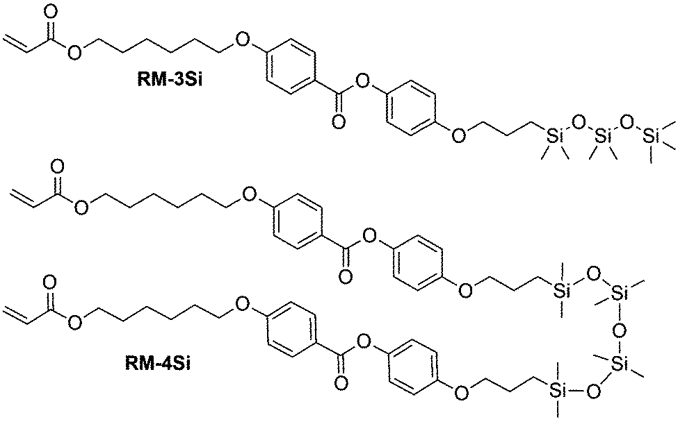 | ||
| Scheme 1 Molecular structures of the reactive ODMS mesogens RM-3Si and RM-4Si. | ||
Results and discussion
Reactive mesogens RM-3Si and RM-4Si (Scheme 1) were synthesized according to Scheme 2. 4-(Allyloxy)phenyl acetate 1 was prepared by acetylation of 4-(allyloxy)phenol.38 Protection of this phenol as an acetate was required for the subsequent catalytic hydrosilylation reaction with siloxane hydrides. To prepare RM-3Si, 1.1 eq. of 1 was reacted with 1.0 eq. of 1,1,1,3,3,5,5-heptamethyltrisiloxane in the presence of dichloro(1,5-cyclooctadiene)platinum(II) in toluene, overnight at 60 °C in a Schlenk setup, to give 2a (yield 50%). The acetate protecting group was removed with ammonium hydroxide in methanol to obtain 3a as a clear viscous fluid (yield 71%). Procedures described in the literature were used to obtain 4-(6-acryloyloxyhexyloxy)benzoic acid12 (6OBA), which was reacted with 1.0 eq. of 3a in an esterification reaction using dicyclohexylcarbodiimide (DCC) and 4-dimethylaminopyridine (DMAP) to obtain RM-3Si (yield 28%). For preparation of the RM-4Si, 2.2 eq. 1 was reacted with 1.0 eq. of 1,1,3,3,5,5,7,7-octamethyltetrasiloxane under identical conditions as the preparation of 2a to obtain 2b (yield 67%). After deprotection 3b was obtained (yield 87%) which was reacted with 2.0 eq. 6OBA to form the desired product RM-4Si (yield 89%). The ODMS RMs were purified by column chromatography and characterized by TLC, NMR, TGA, and MALDI-TOF MS (characterization data are gathered in the ESI†).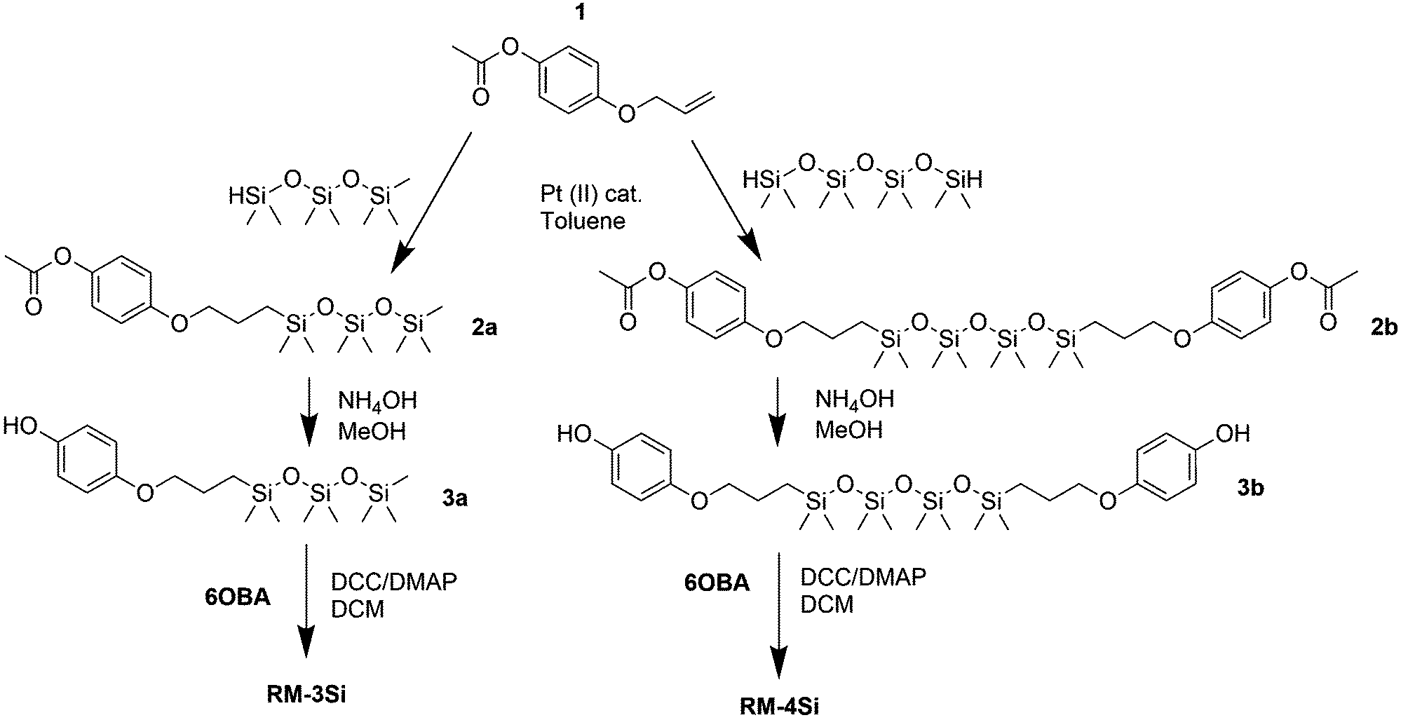 | ||
| Scheme 2 Synthetic routes for the preparation of reactive mesogens RM-3Si and RM-4Si. | ||
To investigate the LC phase behavior, the LCs were analyzed by differential scanning calorimetry (DSC), X-ray diffraction (XRD), and polarized optical microscopy (POM). Fig. 1a shows the DSC data obtained on second cooling of the two compounds. The phase transition temperatures of RM-3Si are I → 31.7 °C (7.93 J g−1) → SA → 0.39 C (36.79 J g−1) → K. Meanwhile, the phase transitions for RM-4Si are I → 58.4 °C (11.22 J g−1) → SA → −4.5 °C (13.93 J g−1) → K. Here, K, SA, and I denote the crystalline, smectic A, and isotropic phases, respectively, and the associated enthalpy changes are given in parentheses. In both cases, the compounds are liquid crystalline at room temperature. Compared to similar LCs without an ODMS segment, crystallization is suppressed,39 an effect likely due to the high flexibility of the siloxane oligomers.33,40 For the same reason, the isotropization temperature is suppressed.16Fig. 1b shows the room temperature X-ray diffraction (XRD) spectra measured in both wide-angle and medium-angle configurations on kapton tape (see methods). For RM-3Si, two sharp diffraction peaks are found at medium angles (q = 1.58 nm−1 and q = 3.15 nm−1), which corresponds to a periodic layered structure with an interlayer distance of d = 4.0 nm. Since this value is approximately equal to the molecular length (determined by MM2 molecular simulation), it follows that the LC phase of RM-3Si can be assigned as a smectic A phase. For RM-4Si, two sharp diffraction peaks are found at medium angles (q = 1.71 nm−1 and q = 3.42 nm−1), corresponding to a layered structure with an interlayer distance of d = 3.6 nm. Since the interlayer distance is approximately equal to half the length of the extended dimer, the LC phase of RM-4Si is assigned as a smectic A phase, in which the siloxane bridge and organic tail moieties are partially mixed.32,41,42 For both LCs, a broad peak is observed in the wide-angle region, signifying a combination of siloxane–siloxane interactions at 0.70 nm,37 organic-organic interactions at 0.45 nm, and intermediate organic–siloxane interactions at 0.55 nm. This indicates that there is partial nanophase segregation between siloxane and organic units, which is presumably the driving force behind the formation of the smectic layered morphologies,16 rather than the lower-order nematic ordering.39 Schematic representations of the liquid crystal phases are included in Fig. 1c, in which the mesogenic core (red) form layers with the partially phase separated siloxane (blue) and reactive aliphatic tails (black).
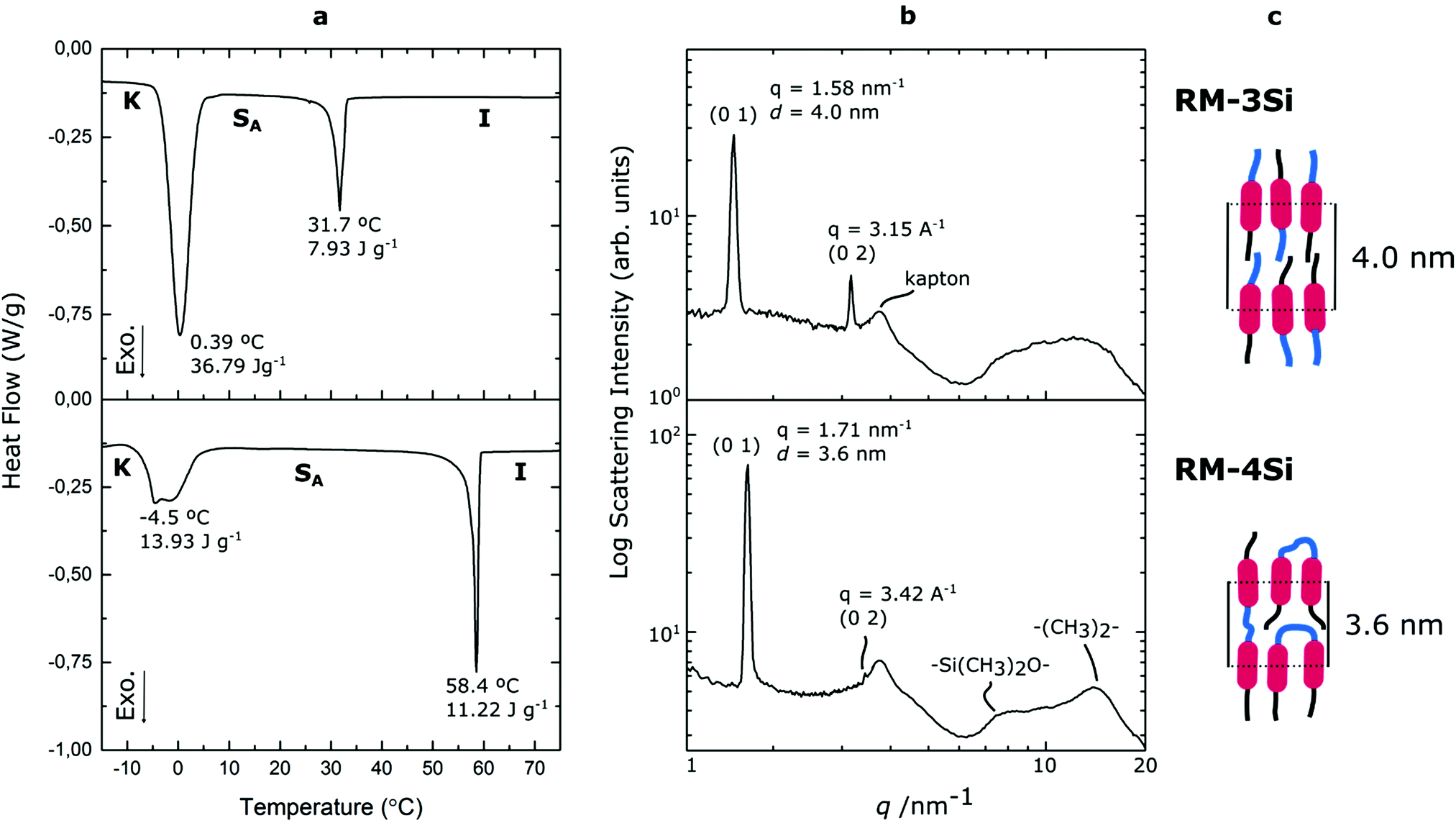 | ||
| Fig. 1 (a) DSC thermographs and (b) room-temperature X-ray diffraction spectra of the reactive siloxane liquid crystals. The assigned Miller indices and the respective intermolecular scatterings are indicated, as well as the assigned lattices. (c) Schematic representation of the room-temperature smectic phases formed by the liquid crystals; mesogenic core (red), ODMS (blue) and reactive aliphatic tails (black). | ||
To photopolymerize the reactive hybrid mesogenes, a cell (∼7 μm) was filled with the LCs containing a small amount of photoinitiator. When observed under crossed polarizers in a POM experiment (Fig. 2a), the LCs exhibit a fan-shape texture characteristic of the smectic A phase. The cell was subsequently exposed to UV for 20 min at room temperature. Under these conditions, Fourier Transform Infrared Spectroscopy (FTIR) indicated the complete conversion of reactive acrylate groups, by the disappearance of the peak at 1635 cm−1 that corresponds to the C![[double bond, length as m-dash]](https://www.rsc.org/images/entities/char_e001.gif) C bond of the acrylates (Fig. S1, ESI†). The birefringence is largely maintained in the polymerized samples (Fig. 2b), indicating the ‘freeze-in’ of the SmA phase in the polymeric material. The polymerized samples were further heated under the POM to explore the stability of the LC phase (Fig. 2c). In this case, the thermal transitions of the monomers were not observed. Instead, the linear RM-3Si polymer showed a reversible isotropic phase transition at 175 °C, which represents a significant increase compared to the corresponding monomer. The crosslinked liquid crystal network of RM-4Si did not become isotropic within the studied temperature range (<250 °C). However, it showed a reversible phase transition at 175 °C, accompanied by a lower birefringence. DSC performed on the polymeric material further confirm the stability of the polymerized films (Fig. S2, ESI†).
C bond of the acrylates (Fig. S1, ESI†). The birefringence is largely maintained in the polymerized samples (Fig. 2b), indicating the ‘freeze-in’ of the SmA phase in the polymeric material. The polymerized samples were further heated under the POM to explore the stability of the LC phase (Fig. 2c). In this case, the thermal transitions of the monomers were not observed. Instead, the linear RM-3Si polymer showed a reversible isotropic phase transition at 175 °C, which represents a significant increase compared to the corresponding monomer. The crosslinked liquid crystal network of RM-4Si did not become isotropic within the studied temperature range (<250 °C). However, it showed a reversible phase transition at 175 °C, accompanied by a lower birefringence. DSC performed on the polymeric material further confirm the stability of the polymerized films (Fig. S2, ESI†).
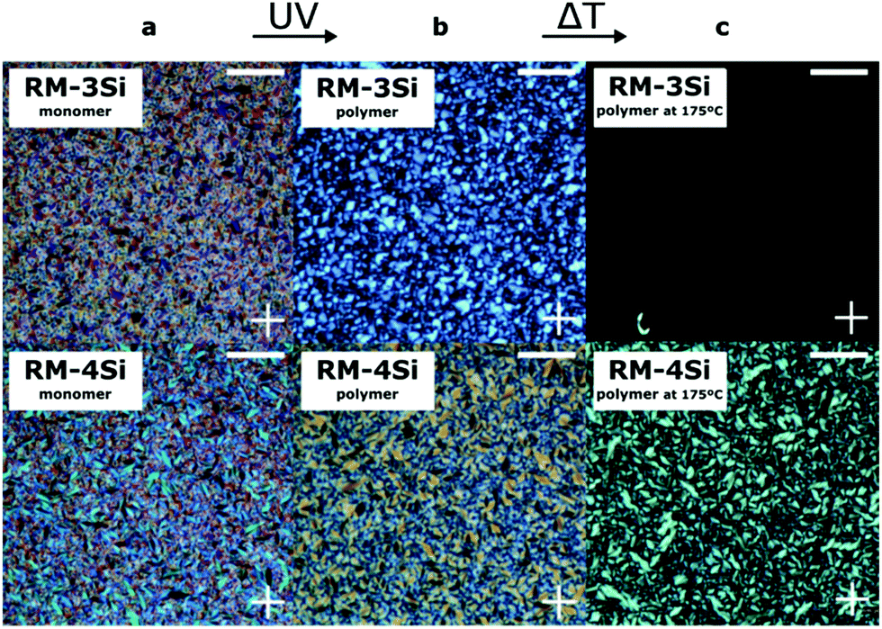 | ||
| Fig. 2 POM images obtained between crossed polarizers of the LCs in a cell (a) before photopolymerization, (b) after photopolymerization, and (c) after heating the samples. Crossed polarizer axes are indicated with a cross. All scale bars: 100 μm. | ||
In order to prepare nanostructured thin films, dilute solutions of RM-4Si were spin coated on a Si wafer containing an Anti-Reflective Coating (ARC), and subsequently polymerized (see Experimental). The solution concentration was varied between 0.25 wt% and 1 wt%, to yield film thicknesses after polymerization between 11 nm (∼3 smectic layers) and 60 nm (∼17 smectic layers) (Fig. S3, ESI†). Across the thickness range, the static contact angle (H2O) of the polymerized films was equal to 105° (Fig. S3, ESI†). Since this value is approximate to the contact angle for PDMS (∼107°),43 it suggests the predominant presence of siloxanes at the air interface.
The polymerized film of 60 nm thickness was studied with wide-angle grazing-incidence X-ray diffraction (GIWAXS) to determine the through-film morphology. In the small-angle region, scattering peaks are observed at q = 1.84 nm−1 and q = 3.66 nm−1, perpendicular to the substrate, corresponding to a layered structure with a periodicity of 3.4 nm. Hence, the smectic LC phase is maintained in the thin polymerized film, and organized preferentially in a homeotropic orientation. Likely, the homeotropic orientation is driven by the low surface energy of PDMS (γPDMS = 20.5 mN m−1),43 as previously reported for siloxane-based LC thin films.20 The broad reflections at 7 nm−1 < q < 14 nm−1 signify that the isotropic nature of the respective intermolecular interactions (siloxane–siloxane and organic–organic) is maintained upon photopolymerization. Comparison of the samples before and after photopolymerization (Fig. S4, ESI†), reveals that the smectic LC order is maintained upon photopolymerization.
Low-resolution AFM height images of the 60 nm thin film show a layered hole-island morphology (Fig. 3b) with a step-height of approximately 3.5 nm, confirming the presence of smectic layers at the film surface. While the films are generally smooth (RMS roughness ∼0.55 nm), holes of approximately 10–100 nm diameter are present on the film surface. High-resolution AFM images, obtained in peakForce tapping mode, further indicate the presence of small defects (5–20 nm diameter) on the film surface (Fig. S5, ESI†).
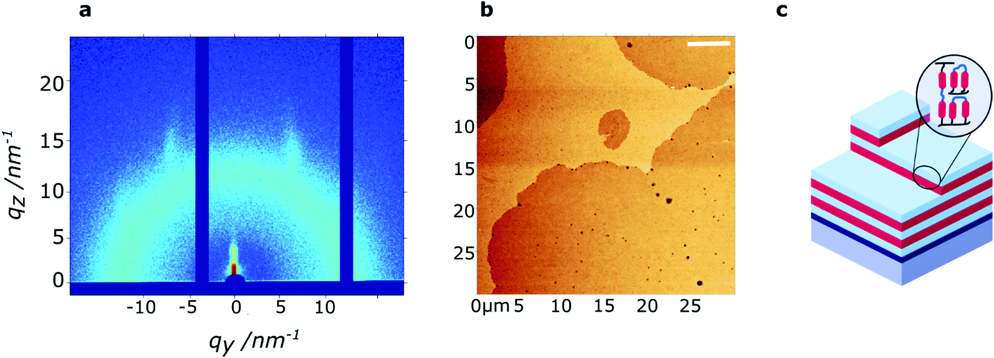 | ||
| Fig. 3 Characterization of a polymerized RM-4Si thin film of 60 nm thickness. (a) grazing-incidence X-ray diffraction data, measured around the critical angle, obtained at room temperature. (b) Low-resolution AFM height image, obtained at room temperature. Scale bar: 5 μm. (c) Schematic representation of the nanostructured thin film. | ||
Finally, micropatterning was achieved by exposing a 60 nm film of RM-4Si through a mask (25 μm diameter circular holes). After the mask exposure, the nonpolymerized material was removed by developing the film in the casting solvent. Optical microscopy revealed the presence of circular features corresponding to the dimensions of the mask (Fig. 4a). Interestingly, the features are surrounded by an additional structure at the edges, observable as a yellow ring. Since the optical contrast arises due to height differences in the film, the film was further characterized by optical profilometry (Fig. 4b). Here, the rings appear as protrusions which rise up to 50 nm above the circular features, which is remarkable considering the initial height of the film (60 nm). This phenomenon is likely due to the diffusion of reactive mesogens to areas of low concentration during the polymerization process.44 A cross-section across the circular features (black line) (Fig. 4c) indicates that the height of the circular features is approximately 30–40 nm, which is lower than the initial height of the film (60 nm). This may be due to (limited) polymerization in the unexposed areas due to diffuse light.
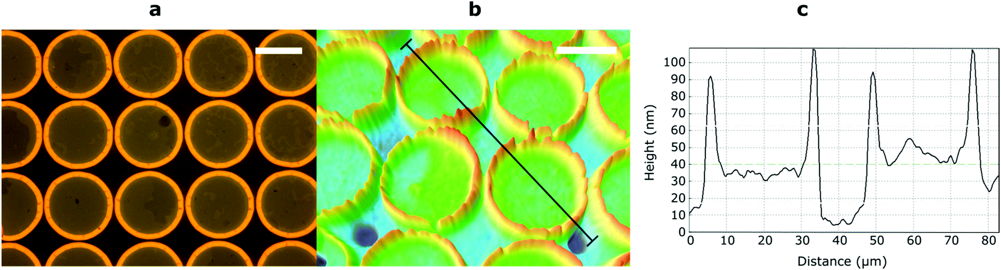 | ||
| Fig. 4 Characterization of a micropatterned RM-4Si thin film of 60 nm thickness. (a) Optical microscopy image. (b) Optical profilometric image with cross-section (black line) (c) cross-section profile corresponding to (b). Scale bars: 20 μm. | ||
Conclusions
In this study, an oligo(dimethylsiloxane)-based reactive monoacrylate and a similar diacrylate were prepared and fully characterized. The room-temperature smectic phases formed by these compounds were shown to be ‘frozen-in’ through photopolymerization, resulting in the preparation of stable nanostructured polymers. Aligned thin films were fabricated by spin-coating and subsequent photopolymerization. These films exhibit smectic layers aligned parallel throughout the film (GIWAXS) and at the surface (AFM), likely driven by the low surface energy of the ODMS. Finally, the in situ polymerization approach allows for micropatterning. Hence, this fabrication method is highly suitable for the preparation of aligned nanostructured polymers with applications as thin-film actuators or well-defined membrane materials.Experimental
The reactive LC mixtures used for the experiments contain the reactive mesogens as well as 2 wt% of photo initiator 1-hydroxy-cyclohexyl-phenyl ketone (Irgacure 184, Ciba Speciality Chemicals). To make homogenous blends, the components were dissolved in chloroform and the solvent was evaporated. For thin film preparation, dilute solutions were spin coated at 3000 rpm for 45 seconds. For photopolymerization, the LCs were irradiated while under nitrogen atmosphere for 20 minutes, at room temperature with 365 nm light from a Mercury lamp (∼5 mW cm−2). Film thickness was obtained using a Bruker DektakXT stylus profiler. Film thickness was obtained from polymerized films only due to the very soft nature of the as-deposited films. Polarized optical microscopy (POM) was performed with crossed polarizers using a Leica DM6000M equipped with a DFC420C camera and a Linkam THMS600 hot-stage for temperature control. For characterization of the LC textures, a small amount of LC material was placed between microscope slides, heated to the isotropic phase, and cooled (5 °C min−1) to room temperature. Phase transition temperatures of the reactive mesogens were determined using a TA Instrument Q1000 differential scanning calorimeter (DSC). 3–4 mg of material was hermitically sealed in aluminum pans. The heating and cooling rate was 5 °C min−1 and the second cooling curve was used to determine the transition temperatures. X-ray scattering measurements were performed on a Ganesha lab instrument equipped with a GeniX-Cu ultralow divergence source producing X-ray photons with a wavelength of 1.54 Å and a flux of 1 × 10⁸ ph s−1. Scattering patterns were collected using a Pilatus 300 K silicon pixel detector. The beam center and the q range were calibrated using the diffraction peaks of silver behenate. Due to the sticky nature of the LCs, XRD samples were prepared by placing a small amount of LC between kapton tape, leading to a background signal at q = 0.39. The sample to detector distance was 91 mm for wide-angle measurements and 441 mm for medium-angle measurements, and the spectra were concatenated at q = 0.36. Grazing incidence XRD was performed at the critical angle (∼0.18°). The AFM data were recorded in ambient conditions using a Dimension ICON atomic force microscope (Bruker Nano Inc., Santa Barbara, CA) fitted with an NCHV silicon probe (Bruker, spring constant 42 N m−1 and a resonance frequency 320 kHz). Fourier transform infrared spectroscopy (FTIR) spectra were obtained using a FTS 6000 spectrometer from Bio-Rad equipped with Specac Golden gate diamond ATR and were signal-averaged over 50 scans at a resolution of 1 cm−1. Optical profilometric measurements were performed on a Sensofar Plμ 2300 microscope equipped with a lens with 150× zoom using blue light.Acknowledgements
This research is supported by the Dutch Technology Foundation STW, which is part of the Netherlands Organisation for Scientific Research (NWO), and which is partly funded by the Ministry of Economic Affairs. Ph. Leclère is Senior Research Associate from FRS-FNRS (Belgium). The X-ray diffractometer was financed by The Netherlands Organisation for Scientific Research (NWO).References
- D. J. Broer, C. M. W. Bastiaansen, M. G. Debije and A. P. H. J. Schenning, Angew. Chem. – Int. Ed., 2012, 51, 7102–7109 CrossRef CAS PubMed.
- J. P. F. Lagerwall and G. Scalia, Curr. Appl. Phys., 2012, 12, 1387 CrossRef.
- T. Kato, N. Mizoshita and K. Kishimoto, Angew. Chem., Int. Ed., 2006, 45, 38–68 CrossRef CAS PubMed.
- C. L. van Oosten, C. W. M. Bastiaansen and D. J. Broer, Nat. Mater., 2009, 8, 677–682 CrossRef CAS PubMed.
- D. Liu and D. J. Broer, Nat. Commun., 2015, 6, 8334 CrossRef CAS PubMed.
- H. Shahsavan, S. M. Salili, A. Jákli and B. Zhao, Adv. Mater., 2015, 27, 6828–6833 CrossRef CAS PubMed.
- X. D. Feng, M. E. Tousley, M. G. Cowan, B. R. Wiesenauer, S. Nejati, Y. Choo, R. D. Noble, M. Elimelech, D. L. Gin and C. O. Osuji, Acs Nano, 2014, 8, 11977–11986 CrossRef CAS PubMed.
- C. L. Gonzalez, C. W. M. Bastiaansen, J. Lub, J. Loos, K. Lu, H. J. Wondergem and D. J. Broer, Adv. Mater., 2008, 20, 1246–1252 CrossRef CAS.
- H. P. C. van Kuringen, G. M. Eikelboom, I. K. Shishmanova, D. J. Broer and A. P. H. J. Schenning, Adv. Funct. Mater., 2014, 24, 5045–5051 CrossRef CAS.
- S. J. Woltman, G. D. Jay and G. P. Crawford, Nat. Mater., 2007, 6, 929–938 CrossRef CAS PubMed.
- J. Lub, V. Recaj, L. Puig, P. Forcén and C. Luengo, Liq. Cryst., 2004, 31, 1627–1637 CrossRef CAS.
- D. J. Broer, J. Boven, G. N. Mol and G. Challa, Makromol. Chem., 1989, 190, 2255–2268 CrossRef CAS.
- J. Lub and D. Broer, Cross-Linked Liquid Crystalline Systems, CRC Press, 2011, pp. 3–47 Search PubMed.
- I. Dierking, Adv. Mater., 2000, 12, 167–181 CrossRef CAS.
- For silsesquioxane based hybrid liquid crystals and functional materials, see: G. H. Mehl and I. M. Saez, Appl. Organomet. Chem., 1999, 13, 261–272 CrossRef CAS; Q. Ye, H. Zhou and J. Xu, Chem. – Asian J., 2016, 11, 1322–1337 CrossRef PubMed; X. Wang, C. M. Cho, W. Y. Say, A. Y. X. Tan, C. He, H. S. O. Chan and J. Xu, J. Mater. Chem., 2011, 21, 5248–5257 RSC.
- C. Pugh, J. Y. Bae, J. Dharia, J. J. Ge and S. Z. D. Cheng, Macromolecules, 1998, 31, 5188–5200 CrossRef CAS.
- I. Dierking, L. Komitov, S. T. Lagerwall, T. Wittig and R. Zentel, Liq. Cryst., 1999, 26, 1511–1519 CrossRef CAS.
- S. Westphal, S. Diele, A. Mädicke, F. Kuschel, U. Scheim, K. Rühlmann, B. Hisgen and H. Ringsdorf, Makromol. Chem., Rapid Commun., 1988, 9, 489–493 CrossRef CAS.
- A. Noro, M. Hayashi, A. Ohshika and Y. Matsushita, Soft Matter, 2011, 7, 1667–1670 RSC.
- K. Nickmans, J. N. Murphy, B. de Waal, P. Leclère, J. Doise, R. Gronheid, D. J. Broer and A. P. H. J. Schenning, Adv. Mater., 2016, 28, 10068–10072 CrossRef CAS PubMed.
- R. Achten, A. Koudijs, M. Giesbers, A. Marcelis and E. Sudholter, Mol. Cryst. Liq. Cryst., 2007, 477, 169–176 CrossRef CAS.
- M. Funahashi, Mater. Chem. Front., 2017, 1 10.1039/C6QM00263C.
- M. Funahashi and A. Sonoda, J. Mater. Chem., 2012, 22, 25190–25197 RSC.
- C. A. Ross, Y. S. Jung, V. P. Chuang, F. Ilievski, J. K. W. Yang, I. Bita, E. L. Thomas, H. I. Smith, K. K. Berggren, G. J. Vancso and J. Y. Cheng, J. Vac. Sci. Technol., B: Microelectron. Nanometer Struct. – Process., Meas., Phenom., 2008, 26, 2489–2494 CAS.
- S. J. Clarson and J. E. Mark, in Polymer science and technology, ed. S. J. Clarson and J. A. Semlyen, Prentice Hall PTR, Englewood Cliffs, NJ, 1993, pp. 616–648 Search PubMed.
- M. Wang, L.-X. Guo, B.-P. Lin, X.-Q. Zhang, Y. Sun and H. Yang, Liq. Cryst., 2016, 1–10 Search PubMed.
- S. Guo, K. Matsukawa, T. Miyata, T. Okubo, K. Kuroda and A. Shimojima, J. Am. Chem. Soc., 2015, 137, 15434–15440 CrossRef CAS PubMed.
- A. Sanchez-Ferrer, A. Merekalov and H. Finkelmann, Macromol. Rapid Commun., 2011, 32, 671–678 CrossRef CAS PubMed.
- H. Finkelmann, H.-J. Kock and G. Rehage, Makromol. Chem., Rapid Commun., 1981, 2, 317–322 CrossRef CAS.
- D. J. Gardiner and H. J. Coles, J. Appl. Phys., 2006, 100, 124903 CrossRef.
- L. Li, C. D. Jones, J. Magolan and R. P. Lemieux, J. Mater. Chem., 2007, 17, 2313–2318 RSC.
- W. K. Robinson, P. S. Kloess, C. Carboni and H. J. Coles, Liq. Cryst., 1997, 23, 309–312 CrossRef CAS.
- E. Corsellis, D. Guillon, P. Kloess and H. Coles, Liq. Cryst., 1997, 23, 235–239 CrossRef CAS.
- T. J. Zhang, D. M. Sun, X. K. Ren, L. L. Liu, G. Y. Wen, Z. J. Ren, H. H. Li and S. K. Yan, Soft Matter, 2013, 9, 10739–10745 RSC.
- M. García-Iglesias, B. F. M. de Waal, I. de Feijter, A. R. A. Palmans and E. W. Meijer, Chem. – Eur. J., 2015, 21, 377–385 CrossRef PubMed.
- A. Zelcer, B. Donnio, C. Bourgogne, F. D. Cukiernik and D. Guillon, Chem. Mater., 2007, 19, 1992–2006 CrossRef CAS.
- C. Keith, R. A. Reddy, U. Baumeister and C. Tschierske, J. Am. Chem. Soc., 2004, 126, 14312–14313 CrossRef CAS PubMed.
- R. Murashige, Y. Hayashi, S. Ohmori, A. Torii, Y. Aizu, Y. Muto, Y. Murai, Y. Oda and M. Hashimoto, Tetrahedron, 2011, 67, 641–649 CrossRef CAS.
- M. Portugall, H. Ringsdorf and R. Zentel, Makromol. Chem., 1982, 183, 2311–2321 CrossRef CAS.
- M. Ibn-Elhaj, A. Skoulios, D. Guillon, J. Newton, P. Hodge and H. Coles, J. Phys. II, 1996, 6, 271–279 CrossRef CAS.
- N. Olsson, B. Helgee, G. Andersson and L. Komitov, Liq. Cryst., 2005, 32, 1139–1150 CrossRef CAS.
- N. Olsson, M. Schröder, S. Diele, G. Andersson, I. Dahl, B. Helgee and L. Komitov, J. Mater. Chem., 2007, 17, 2517–2525 RSC.
- S. Wu, Polymer Handbook, Wiley-Interscience, New York, 3rd edn, 1989, vol. VI Search PubMed.
- B. M. I. van der Zande, J. Steenbakkers and J. Lub, J. Appl. Phys., 2005, 97, 123519 CrossRef.
Footnote |
| † Electronic supplementary information (ESI) available. See DOI: 10.1039/c7sm00673j |
| This journal is © The Royal Society of Chemistry 2017 |