DOI:
10.1039/C7SM00437K
(Paper)
Soft Matter, 2017,
13, 3760-3767
Shape of a sessile drop on a flat surface covered with a liquid film†
Received
2nd March 2017
, Accepted 21st April 2017
First published on 4th May 2017
Abstract
Motivated by the development of lubricant-infused slippery surfaces, we study a sessile drop of a nonvolatile (ionic) liquid which is embedded in a slowly evaporating lubricant film (n-decane) on a horizontal, planar solid substrate. Using laser scanning confocal microscopy we imaged the evolution of the shape of the liquid/liquid and liquid/air interfaces, including the angles between them. Results are compared to solutions of the generalized Laplace equations describing the drop profile and the annular wetting ridge. For all film thicknesses, experimental results agree quantitatively with the calculated drop and film shapes. With the verified theory we can predict height and volume of the wetting ridge. Two regimes can be distinguished: for macroscopically thick films (excess lubrication) the meniscus size is insensitive to changes in film thickness. Once the film is thin enough that surface forces between the lubricant/air and solid/lubricant interfaces become significant the meniscus changes significantly with varying film thickness (starved lubrication). The size of the meniscus is particularly relevant because it affects sliding angles of drops on lubricant-infused surfaces.
Introduction
Understanding the wetting of surfaces is not only of fundamental importance but is relevant for many applications that range from protective coatings to heat transfer. One way of changing the wetting behavior between a solid surface and a liquid is to coat the surface with a thin lubricating film of a second liquid that is immiscible with the first one. Typical examples are metals coated with an oil film for lubrication or to prevent corrosion.1–4 The question we address here is: how does a drop of a liquid wet a thin film of an immiscible liquid on a planar solid support? Studying this four-phase system was also motivated by the recently developed lubricant-infused surfaces, also called slippery liquid infused porous surfaces (SLIPS). Lubricant-infused surfaces consist of a horizontal, porous surface, which is infused with a liquid, the lubricant.5–8 The porous layer hinders the lubricant from flowing off when the surface is tilted. A drop of a second, immiscible liquid is placed on top. Lubricant-infused surfaces have attracted attention because the drop easily slides over the surface.6,9 When tilting the surface by only few degrees the drop slides downhill. This low static friction leads to a number of potential applications, such as improved heat transfer due to enhanced condensation,10,11 suppressed biofouling,12,13 tunable transparency,14 anti-icing,15,16 or containers for residue-free storage of e.g. food.17
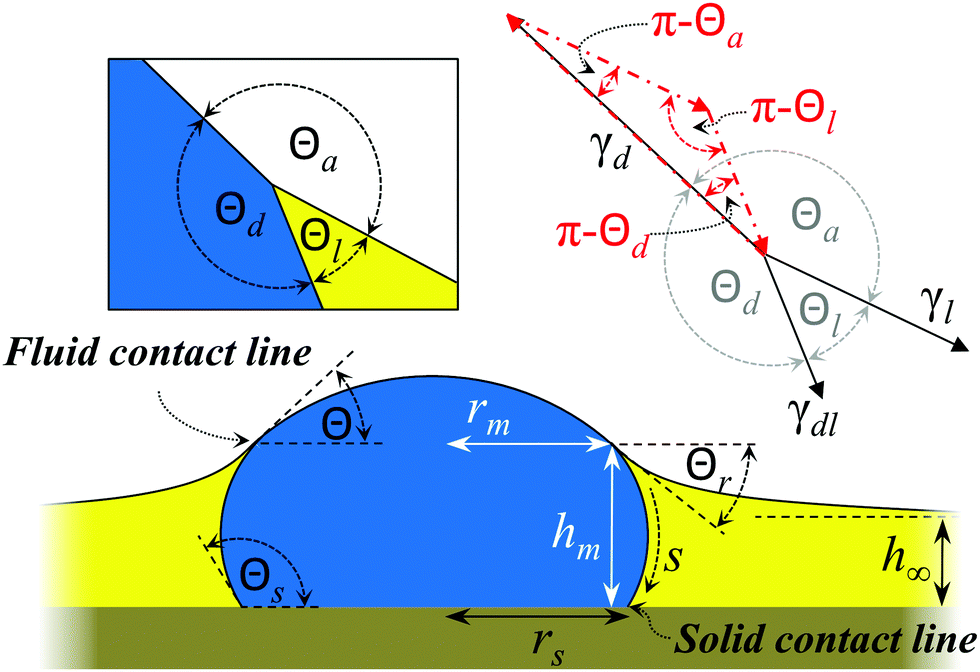
Different morphologies of drop and lubricant are possible, depending on whether the lubricant fully wets and cloaks the drop or whether it forms an intervening film between drop and solid substrate.7,18 Aiming for a quantitative understanding of the shape of the drop and the wetting ridge we focus on the underlying prototype: a liquid drop in direct contact with a smooth planar solid substrate surrounded by a lubricant film (Fig. 1). For this model system we present experimental data and compare it to numerical and analytical calculations which coincide quantitatively in the relationship between film thickness, drop shape, meniscus height and the angles formed between interfaces.
 |
| | Fig. 1 Scheme of a sessile drop surrounded by a lubricant film on a planar solid substrate. The lubricant fully wets the substrate but forms a defined angle with the drop; it does not fully cloak the drop. The left inset shows the drop/lubricant/air three-phase contact line and the respective contact angles. The right inset sketches vectors with lengths corresponding to the interfacial tensions and directed tangential to the respective interfaces (black solid vectors). Stringing these three vectors tip to end together forms the Neumann triangle (red dash-dotted vectors). The fluid contact line is the line at which lubricant, IL, and air meet. The solid contact line is the line at which the solid substrate, lubricant and IL meet. | |
Materials and methods
As a model system we imaged sessile drops of the non-volatile ionic liquid (IL) 1-ethyl-3-methylimidazolium bis(trifluoromethyl-sulfonyl)imide (Sigma, purity >97%) in a film of n-decane (Sigma, purity >99%) as a lubricant. Although posing an untypical drop-lubricant-system, this choice provides several advantages: both liquids are nearly immiscible, allow for simultaneous separate detection (see below), and the evaporation rate of decane enables imaging on a reasonable time scale for different film thicknesses while the IL drop size remains stable. The refractive indices, mass densities and surface tensions at 20 °C were 1.424 ± 0.001, ρd = 1518 ± 3 kg m−3, γd = 0.0358 ± 0.0002 N m−1 for the IL and 1.413 ± 0.001, ρl = 738 ± 3 kg m−3, γl = 0.0240 ± 0.0002 N m−1 for decane. These values refer to IL saturated with decane and decane saturated with IL; both were dyed with 10−3 wt% N-(2,6-diisopropylphenyl)-3,4-perylenedicarboxylic acid monoimide (PMI). The surface tensions of the pure liquids were not significantly different (0.0367 N m−1 for the IL and 0.0239 N m−1 for decane). The interfacial tension between IL and decane was γdl = 0.0122 N m−1. Interfacial tensions were measured with a Wilhelmy plate tensiometer (DCAT11 Dataphysics).
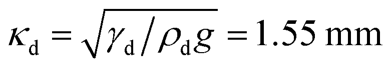
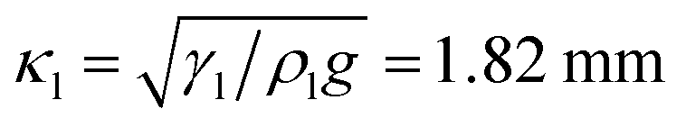
In each experiment, a drop of IL of ≈0.2 nL was placed on a dry microscope cover slide with a thin syringe needle. The drop forms a static contact angle of ≈50°–80° with the cover slide. Here we restrict ourselves to drops which are much smaller than their capillary length, 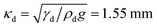 (g = 9.81 m s−2 is the gravitational acceleration), so that the effect of gravitation on the drop shape remains negligible. Rather than the drop/air interface one can also consider the capillary length related to the drop/lubricant interface:
 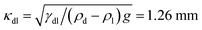 .
.
After depositing the drop, decane was added. It spreads and fully wets the cover slide, but does not underspread the drop of IL. We always started with films of more than 200 μm thickness so that initially the drop was fully covered by decane (Fig. 2). During the gradual evaporation of decane (vapor pressure 195 Pa at 20 °C) the whole range of film thicknesses could be explored down to zero.
 |
| | Fig. 2 Nonvolatile drop embedded in a volatile lubricant. (a) Confocal microscopy image of a drop of ionic liquid placed on a film of the lubricant n-decane. (b) Fits of the contour of the interfaces at t = 209 s. Dark yellow: drop/air interface; red: drop/lubricant interface; blue: air/lubricant interface; green: substrate surface. The solid lines represent the curves fitted to the data while the dashed and dotted lines represent the radii of curvature of drop/lubricant and the drop/air interface, respectively. (c) Confocal microscopy images of the right hand side of the drop combined with the numerically calculated phase boundaries (same colour code as in (b)) shown on the left. | |
Drop and lubricant were imaged with a laser scanning confocal microscope (Leica SP8, HCX PL APO 40× water objective), in the following termed confocal microscopy. The resolution was <400 nm in horizontal and <1 μm in vertical direction. The dye PMI is soluble in both decane and IL. The emission spectra of the dye PMI in decane and IL are sufficiently different, so that we could detect both liquids in two channels simultaneously (Fig. S1, ESI†). During the evaporation of decane, vertical cross sections (xz-plane) through the drop center were recorded. Images were processed to extract the contours of the drop and the lubricant (open source image analysis software FIJI, Fig. 2b and Fig. S2, ESI†). In the fitting procedure of the contours, the refractive indices of decane and the ionic liquid were taken into account to correct for a slight distortion of the images in z-direction.
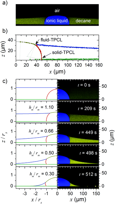
As decane gradually evaporated, at some point the top of the drop pierced through the decane/air interface. A drop/lubricant/air three-phase contact line (fluid contact line) formed. We define t = 0 s as the point where the lubricant film ruptured on top of the droplet and a drop/air interface formed. As the evaporation continued, the radius rm of the fluid contact line defined in Fig. 1 increased, exposing more and more free surface of the drop (Fig. 2c). During the whole evaporation process, the drop remained pinned to the substrate; i.e. the contact radius rs of the drop/lubricant/solid three phase line (solid contact line) remained constant, while the contact angle ΘS with the solid, changed. Here, ΘS is the angle of the drop/lubricant interface with the solid/drop interface inside the drop.
The quantitative evaluation of a representative experiment is shown in Fig. 3. The film thickness h∞ (height far away from the droplet) decreased linearly with time as expected for film evaporation (Fig. 3a, blue circles).19,20 In contrast to the linear decrease of h∞, the maximum height of the wetting ridge of lubricant hm (Fig. 3a) decreased by less than 10 μm within the first 490 s. Only during the final phase of evaporation hm decreased rapidly.
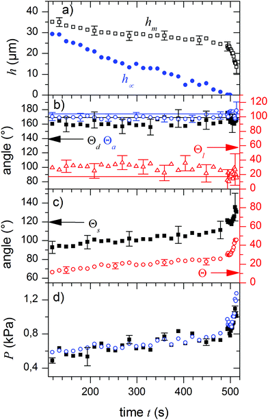 |
| | Fig. 3 Parameters of drop and meniscus shape during evaporation. (a) Film thickness at large distance to the drop, h∞ (blue), and height of the fluid three-phase contact line, hm, (black squares). (b) Temporal development of the angles between the phase boundaries at the fluid three-phase contact line, Θa, Θd, Θl, i.e. the Neumann angles. The solid lines represent the values for the Neumann angles according to eqn (1) with independently measured surface tensions. (c) The contact angle of the drop at the solid-TPCL, Θs, and the angle of the drop-air interface at the liquid TPCL with respect to the horizontal, Θ, which quantifies the rotation of the Neumann triangle. (d) Young–Laplace pressure in the drop as calculated from the radii of curvature of the air/drop (black) and the drop/lubricant (blue) interfaces. In all cases values measured on the right and left sides of the drop were averaged. Errors are smaller than or equal to symbol size unless they are indicated. | |
Contact angles
The boundary conditions at the fluid contact line are expected to fix the angles between the interfaces as given by the Neumann triangle:21–24| | 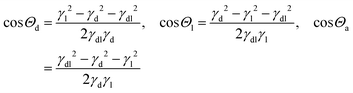 | (1) |
Here, Θd, Θl, and Θa denote the angles inside the droplet, the lubricant and the surrounding vapor phase, respectively (Fig. 1).
Indeed, we observed that during the whole process of lubricant evaporation, the Neumann angles remained constant (Fig. 3b). The solid lines in Fig. 3b are the Neumann angles as calculated from the measured surface tensions according to eqn (1). The deviations between measured and calculated angles reflect the experimental error in measuring the angles at the fluid contact line.
Although the Neumann angles remain constant, the whole Neumann triangle rotates. We quantify the rotation of the triangle by the angle Θ between the drop/air interface and the horizontal (Fig. 1). Just before decane had fully evaporated (t ≈ 500 s) the Neumann triangle rotated from 12° to 43°. While rs remained constant, the capillary action of the lubricant meniscus reduced the overall aspect ratio of the drop.
In addition to the rotation of the Neumann triangle, ΘS weakly increased during the first 490 s, followed by a fast increase in the last seconds of evaporation. This is in contrast to the “inverse” situation of a volatile drop and a non-volatile lubricant; here the drop evaporates keeping the solid contact angle ΘS constant.25
Shapes of the interfaces
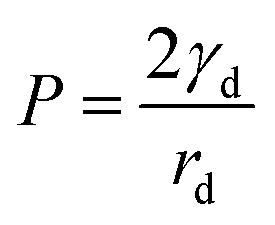
The shapes of the drop/lubricant and drop/air interfaces are determined by Laplace equations and boundary conditions at the three-phase contact lines. As long as the lubricant film fully covers the drop and still has a planar free surface, the Laplace pressure inside the drop is P(t = 0) = 2γdl/r0, where r0 is the initial radius of curvature of the drop. For the example shown in Fig. 2 and 3r0 = 47 μm and P(t = 0) = 519 Pa.
After a fluid contact line was formed, the drop/air interface at the top of the drop is shaped like a spherical cap with a radius of curvature rd. The Laplace pressure inside the drop is
| |  | (2) |
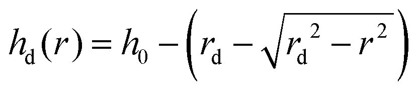
The drop/air interface is described by a circular arc according to
| | 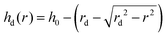 | (3) |
Here,
h0 is the height at the center of the drop.
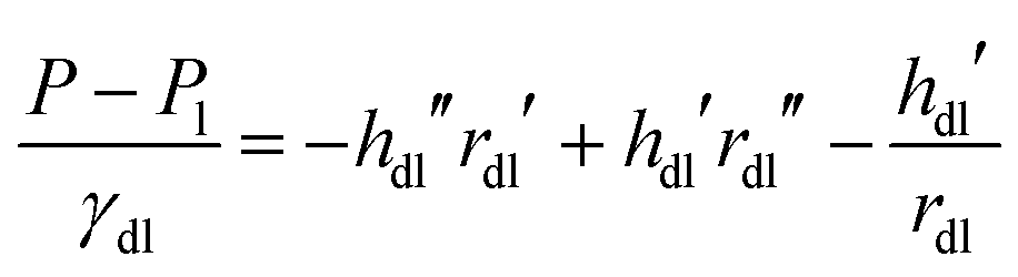
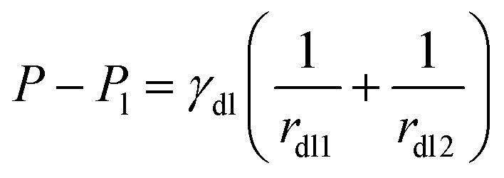
The drop/lubricant interface is shaped similar to a part of a torus. Due to symmetry, the radii of the two principal curvatures, rdl1 and rdl2, represent the radii of curvature in the xz-plane and the corresponding orthogonal direction, respectively. The former of these curvatures is directly imaged in the cuts of the xy-plane while the latter is determined at the same spot but in perpendicular direction. Since in equilibrium the Laplace pressure in the drop is the same throughout the whole drop, these radii are related by26
| | 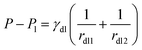 | (4) |
Here,
Pl is the pressure inside the lubricant. Hydrostatic effects can be neglected since the drop is small. The contours of the drop/air and the drop/lubricant interfaces could be well approximated by circular arcs (
Fig. 2b); the dotted and dashed lines mark the different radii of curvature.
During the evaporation of the lubricant, the Laplace pressure inside the drop gradually increases (Fig. 3d). The pressure increases by approximately 200 Pa during the first 490 s. The subsequent increase by 500 Pa reflects the strong deformation of the drop during the last stages of evaporation. Eventually, all lubricant has evaporated and the final radius of the drop is equal to the initial radius; both radii are equal because the drop is shaped like a spherical cap and the solid contact line is pinned. The final Laplace pressure is P = 2γd/r0 = 1523 Pa, while the hydrostatic pressure in the droplet remained below 1 Pa and can safely be neglected.
To describe the shape of the lubricant film we consider the Young–Laplace equation in radial symmetry. The thickness of the lubricant film is described as a function of the radial coordinate r by hl(r). In this axisymmetric case, additional pressure terms need to be taken into account to obtain the desired shape at large distance, namely hl(r → ∞) = h∞. For relatively thick lubricant layers this will be provided by gravity. However, for the case where the lubricant film is thinner than ≈100 nm, the complete wetting is ensured by the disjoining pressure. Taking disjoining pressure into account, the extended Young–Laplace equation is:27–29
| | 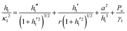 | (5) |
is the capillary length of the lubricant. The first two terms on the right hand side,
hl′′(1 +
hl′
2)
−3/2 +
hl′
r−1(1 +
hl′
2)
−1/2, represent the curvature of the axisymmetric meniscus shape. The primes denote differentiation with respect to
r. The third term on the right hand side takes van der Waals forces into account. The van der Waals length
a is related by
a2 =
AH/6π
γl to the Hamaker constant
AH for air interacting with the solid support across lubricant. With an estimated Hamaker constant of
AH ≈ 2.5 × 10
−20 J
30 we obtain a van der Waals length
a = 0.2 nm.
P∞ is the effective pressure in the film at substrate level. Because absolute hydrostatic pressures are small,
P∞ ≈
Pl.
Numerical solutions
General analytical solutions of eqn (4) and (5) are unavailable. To test their predictive powers and to forecast the shape of the wetting ridge we solved both equations numerically. For the drop/lubricant interface (eqn (4)) a parametric representation, rdl(s), hdl(s) was chosen, where s is the contour length along the profile measured from the fluid contact line. The corresponding Laplace equation is| |  | (6) |
Here, the primes denote differentiation with respect to s. The three contour profiles meet in the fluid contact line which has the radius rm and the height hm. Further, we define s = 0 at the fluid contact line (increasing toward the substrate). Hence| | | hm = hd(r = rm) = hl(r = rm) = hdl(s = 0), rdl(s = 0) = rm | (7) |
The slopes of the three contours with respect to each other at the fluid contact line are given by the Neumann balance of surface tensions at the fluid contact line:| | γd![[thin space (1/6-em)]](https://www.rsc.org/images/entities/char_2009.gif) cosarctanhd′(r = rm) − γdlrdl′(s = 0) = γlcosarctanhl′(r = rm) cosarctanhd′(r = rm) − γdlrdl′(s = 0) = γlcosarctanhl′(r = rm) | (8a) |
| | | γdsinarctanhd′(r = rm) + γdlhdl′(s = 0) = −γlsinarctanhl′(r = rm) | (8b) |
Eqn (8a) results from a balance of forces in horizontal direction. Eqn (8b) balances vertical forces. These equations are fully equivalent to eqn (1). The orientation of the Neumann triangle is parametrized by the angle Θr = Θ + Θa − π between the film surface and the horizontal at the fluid contact line:| | | −arctanhl′(r = rm) = Θr | (9) |
The slopes of the other profiles follow from eqn (8). Further, the slopes of both the drop contour at the center of symmetry as well as the lubricant contour in infinite distance from the drop shall vanish, hd′(r = 0) = 0 and hl′(r → ∞) = 0. Finally, the boundary condition of the drop/lubricant interface at the solid substrate is, in case of a drop pinned to the substrate, given by the corresponding pinning radius, rdl(s = smax) = rs and hdl(s = smax) = 0. Together with these relations and boundary conditions the equations for the pressure drop across the interfaces between drop/air (eqn (2) and (3)), drop/lubricant (eqn (6)) and lubricant/air (eqn (5)) are solved numerically to determine the film profile. For that, the initial values of Θr = 0 and Pl are selected such that the remaining boundary conditions are obeyed for an entirely flat lubricant film. Then, one or more parameters are changed, and new values of Θr and Pl are obtained by a variable-order predictor–corrector algorithm (“shooting”).
Comparison with experimental results
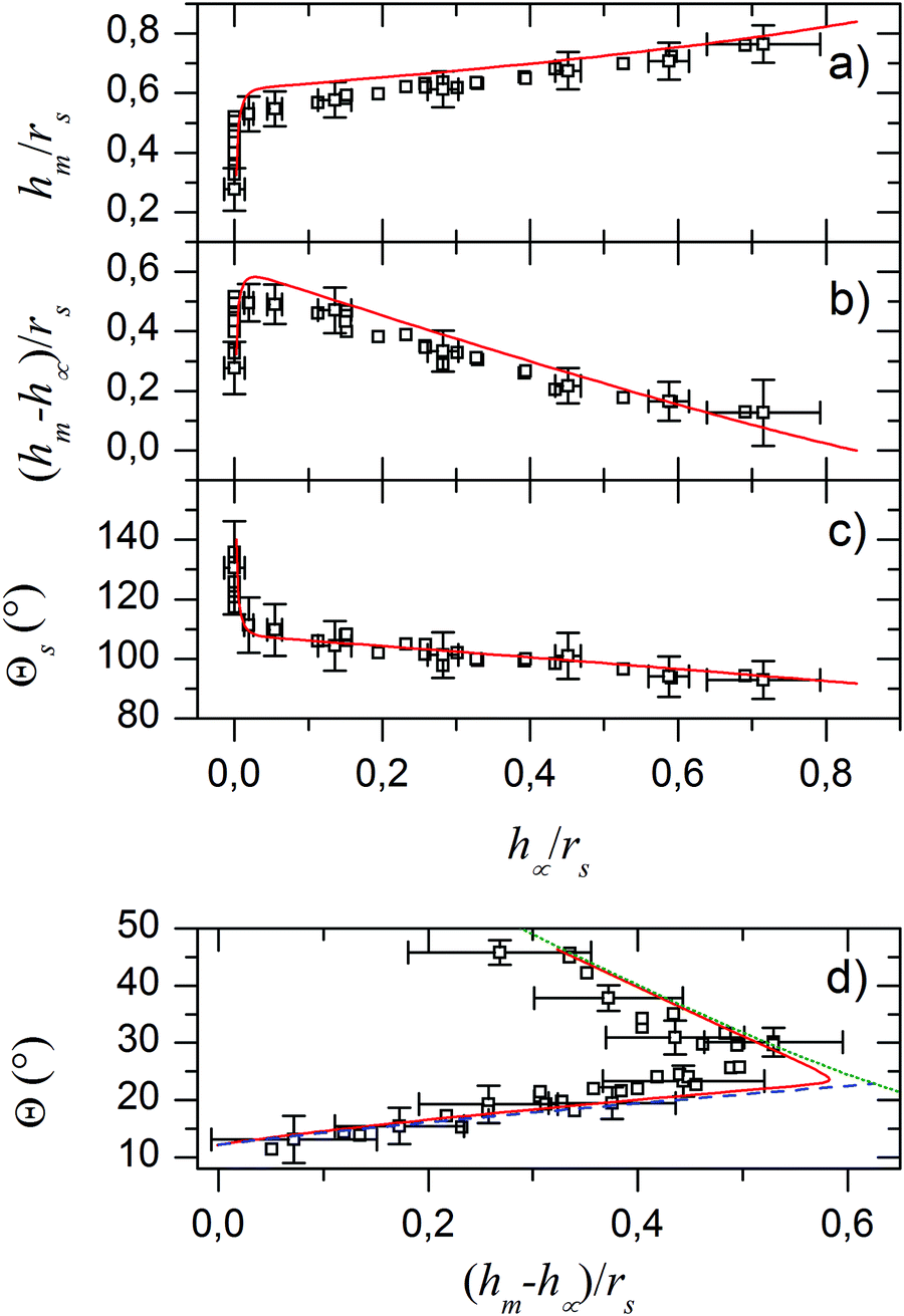
The scaled experimental results coincide with the simulation results (Fig. 2). To further quantify the agreement between the model and experiments we scaled the height of the lubricant film at the fluid contact line hm and the meniscus height hm − h∞ by rs (Fig. 4). The height of the lubricant at the fluid contact line hm decreases monotonically with the film thickness h∞ (Fig. 4a). For almost the whole range of film thicknesses, the height varies weakly. Only for very thin films, that is for h∞ of the order of 200 nm, the height decreases steeply. Please note that, if we follow the evaporation process in time, we go from right to left in the plots in Fig. 4a–c. Correspondingly, for macroscopically thick films the height of the meniscus, hm − h∞ (Fig. 4b), increases roughly linearly with decreasing film thickness. As h∞ reaches microscopic values, the meniscus height sharply decreases to zero. In addition, the solid contact angle increases gradually from 90° to 110° before eventually, in the microscopic regime, it reaches ≈130° (Fig. 4c). This suggests an increasing capillary traction of the meniscus on the droplet.
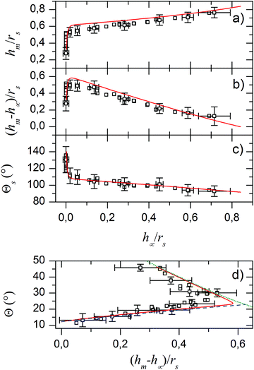 |
| | Fig. 4 Comparison of experimental (black open squares) and numerical results (red solid lines) for different parameters. (a) Height of the fluid contact line hmvs. film thickness h∞ both scaled with respect to the pinned radius of the drop rs. (b) Difference between hm and h∞vs. h∞ both scaled to rs. (c) Contact angle of the drop at the solid TPLC vs. h∞ scaled to rs. (d) Angle between the drop-air boundary and the horizontal Θ vs. (hm − h∞)/rs. Panel (d) also depicts analytical solutions for the asymptotic cases of macroscopic (blue dashed line),32 and microscopic film heights h∞ (green dotted).28 | |
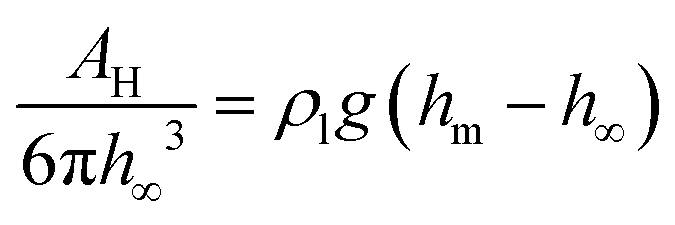
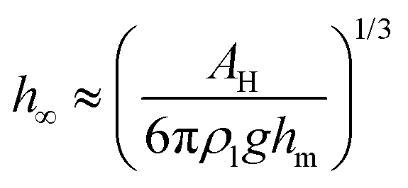
Fig. 4 shows that two regimes can be distinguished. Plotting Θ as a function of hm − h∞, two branches that correspond to distinct physical regimes become even more obvious (Fig. 4d). For macroscopically thick films, hm − h∞ and Θ increase up to a maximum with decreasing film thickness. We shall call this regime “excess lubrication”. Hereafter, the second regime starts: as lubricant continues to evaporate, the meniscus size decreases more steeply. To the precision of the confocal measurement, the lubricant appears to completely wet the substrate. Θ increases while changes in h∞ are below the resolution limit and cannot be used as a reliable independent variable. We will refer to this as “starved lubrication”. The transition is at a film thickness where surface forces, due to van der Waals interactions, and the hydrostatic pressure difference between meniscus and film become equally important for leveling the lubricant at large r:
| |  | (10) |
With
h∞ ≪
hm the transition is at a film thickness of
| |  | (11) |
In our case with
hm of the order of 30 μm (
Fig. 3a) and
AH = 2.5 × 10
−20 J this is at
h∞ ≈ 200 nm.
Analytical approximation for the shape of the lubricant film
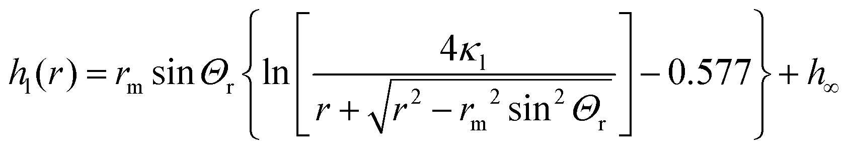
We analyze the regimes of excess and starved lubrication independently. For excess lubrication, the lubricant film is macroscopically thick everywhere, and the disjoining pressure in eqn (5) can be neglected. P∞ defines the reference pressure, i.e. P∞ = 0. For the reduced equation, a general analytical solution is still not available. However, the asymptotic regimes r ≪ κl and r ≫ κl can be solved separately. Then, a quantitative relation between hm − h∞ and Θr can be obtained by the technique of matched asymptotes. Our case is analogous to the meniscus around a vertical rigid cylinder in a liquid pool, as discussed by Derjaguin31 and James.32 However, the radius rm of the “virtual cylinder” needs to be found for a given drop volume. James32 solves the problem by matching the asymptotic expansions between solutions of two distinct regimes. Following the convention of James,32 we define an “outer” regime which is dominated by capillarity and profile slopes may be large. Therefore, full nonlinear curvature terms are considered. This regime is valid for small r, near the liquid contact line. Conversely, the “inner” regime with only small slopes is dominated by the balance of gravity and capillarity, which is valid far from the liquid contact line. For the range of experimental observations (r ≪ κl), the shape of the lubricant meniscus is described by the outer solution, which is a catenoid:32| | 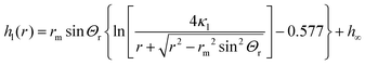 | (12) |
Here, 0.577 approximates the Euler–Mascheroni constant. h∞ was added since in our case, the substrate serves as origin (instead of the liquid level at r → ∞, as in ref. 32). Note that κl appears only as a consequence of the matching to the inner solution (see James32 for details). Within the experimentally accessible range of radii, eqn (12) serves as an excellent approximation to experimental and numerical profiles. Note that eqn (12) is valid only for r ≪ κl and diverges logarithmically for large r. For r comparable to or larger than κl, one would have to use the corresponding inner solution which follows from the balance of gravity and the linearized capillarity terms:| | | hl(r) = rmsinΘr·K0(r/κl) | (13) |
Here, K0 is the modified Bessel function of zeroth order. The blue dashed line in Fig. 4d shows the approximation obtained by solving eqn (1)–(4) together with the condition hm = hl(rm), using eqn (12) to evaluate hl(rm).
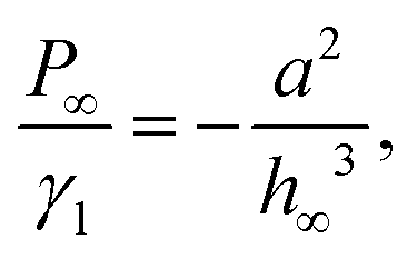
In the regime of starved lubrication, the apparent radius of the macroscopic part of the liquid meniscus is smaller than the capillary length and the hydrostatic term in eqn (5) can be neglected. An analytical solution of the remaining equation is again unavailable. Once more we use matched asymptotic expansions to obtain a functional relation between hm − h∞ and Θr. Here, we follow the approach of Renk et al.:28 the outer regime is again dominated by capillarity, while the inner regime is dominated by the disjoining pressure. In the starved regime, the pressure gauge is
| |  | (14) |
such that the curvature vanishes at large
r and
P∞ is given by the disjoining pressure. Then, for
hl ≫
a,
P∞ is equal to the capillary pressure in the lubricant film.
h∞ is microscopically small and difficult to determine in experiments. For practical reasons, we use
P∞ as an independent parameter rather than
h∞. While in
ref. 28 the authors have used the small slope approximation to obtain the outer solution, the experimental angle
Θr reaches values as high as 40° and quantitative predictions require full nonlinear curvature terms. The inner solution is identical to the one of Renk
et al.28 To leading order, it is simply a constant,
hl =
h∞. The matching condition on the outer solution, as found by
ref. 28, corresponds to a smooth transition between outer and inner solution at some finite radius
r*,
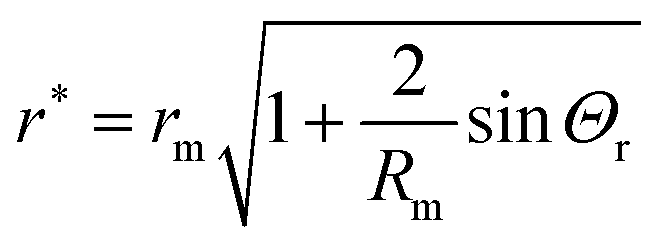
| | | hl(r*) = 0, hl′(r*) = 0, | (15) |
where we approximated
h∞ ∼ 0 on the scale of the outer solution. The radius
r* does not define a physical three phase contact line, but the location of the transition region between outer and inner zones. According to
ref. 28, the width of this transition zone is of order (
γl/|
P∞|)
2/3a1/3 =
h∞2/
a, which is typically in the range of only a few microns or less. Note that
r* is not a free parameter, but follows from
rm,
Θr, and
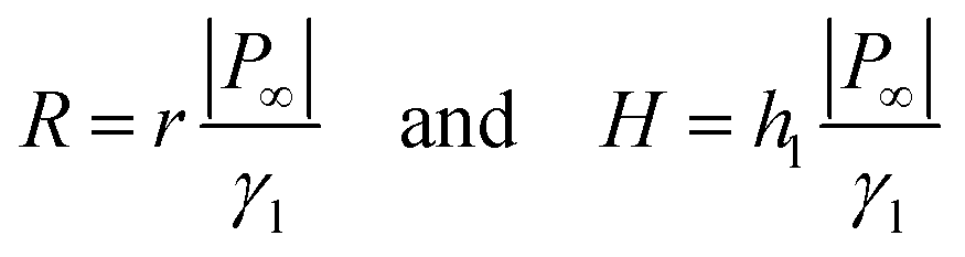
P∞. The natural length scale for the outer problem is set by |
P∞|/
γl, so that we scale
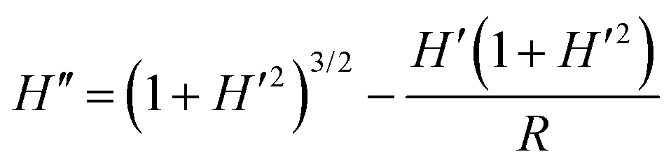
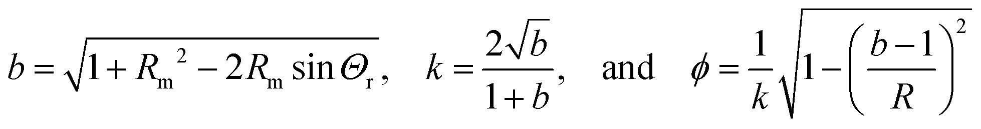
| |  | (16) |
In dimensionless form, the equation for the outer problem defines a surface of constant nonzero mean curvature (a “nodoid”):
| |  | (17) |
| | | H′(Rm) = −tanΘr | (18) |
Here,
H′ = d
H/d
R,
H′′ = d
2H/d
R2,
Rm =
rm|
P∞|/
γl. The analytical solution to
eqn (17), satisfying boundary conditions
(15) and (18), is
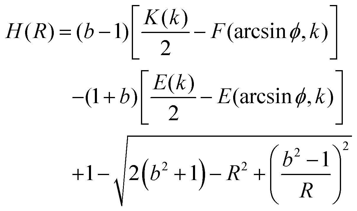
| | 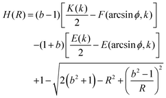 | (19) |
Here,
F(
ϕ,
k) and
E(
ϕ,
k) are the elliptic integrals of first and second kind, respectively, and
K(
k) and
E(
k) are the corresponding complete elliptical integrals. The condition
hm =
H(
Rm)
γl/|
P∞|, together with
eqn (1), (2) and (4) and the drop volume, define a closed set of equations that can be solved for
Θ(
P∞) and
hm(
P∞). The green dotted line in
Fig. 4d shows the solution obtained from this approximation. The apparent radius at which the meniscus height becomes microscopically small evaluates to
| | 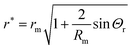 | (20) |
Consequences for sliding
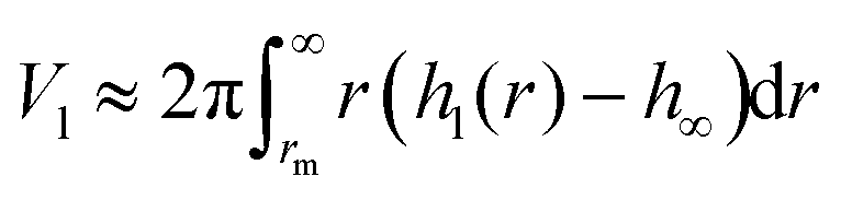
The striking feature of lubricant-infused surfaces is the low sliding angle of sessile drops. In that respect, the formation of a meniscus around the central drop has an important consequence: it decreases the sliding angle of the drop due to an addition of effective mass and the lower interfacial tension, γdl < γd.8 Therefore, we estimate the additional mass caused by the meniscus. In general, a sessile drop slides off an inclined surface when the tilt angle α exceeds a value given by33–37| | 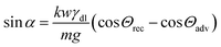 | (21) |
Here, m = Vdρd + Vlρl is the mass of the drop plus wetting ridge, w ≈ 2rS is the width of the apparent contact area between drop and solid support measured perpendicular to the sliding direction, Vd is the volume of the drop, Vl is the volume of the wetting ridge, and k ≈ 1 is a geometry factor.33,36,38–40 When tilting the support, the contact angle Θs at the front increases and at the rear it decreases. Just before the drop starts to slide, these two angles, Θadv and Θrec, are the advancing and receding contact angles of the drop/lubricant interfaces at the front and rear of a drop. Eqn (21) is the result of a force balance between gravitation pulling the drop downhill and the capillary force, i.e. the integral of interfacial tension around the fluid contact line. The volume of the meniscus can be calculated from| | 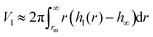 | (22) |
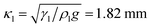
As an example, for the drop shown in Fig. 2 after 449 s with κl = 1.82 mm, hm = 27 μm and rm = 37 μm the volume of the meniscus is Vl = 1.5 nL. Thus the wetting ridge rather than the drop itself dominates sliding for small drops and high wetting ridges.
Drainage of the lubricant
Another important consequence of the presence of a meniscus is the increased drainage of lubricant when drops slide downhill. A sliding drop will drag the lubricant meniscus downhill. Drainage and depletion of lubricant by sliding drops is one implication of meniscus formation. The above results show that with decreasing lubricant film thickness h∞, the extra height of the meniscus hm − h∞ increases. Thus, depletion of the lubricant film becomes stronger for thinning films.
Conclusions
We studied the shape of a liquid drop on a solid support that is (partially) immersed in a thin lubricant film wetting the solid. We solve the extended Young–Laplace equations for the drop/air, drop/lubricant, and lubricant/air interfaces numerically. To verify theoretical results we imaged the three interfaces by laser scanning confocal microscopy with a resolution better than 1 μm. Experiments and predictions cover a range of lubricant film thicknesses from virtually zero to fully embedding the drop.
Two regimes can be distinguished. In the excess lubrication regime (h∞ ≫ 200 nm) the height of the wetting ridge hm is relatively insensitive to changes in film thickness. The meniscus height hm − h∞ decreases roughly linearly with increasing film thickness h∞. In the starved lubrication regime, i.e. for thin lubricant films, the height of the wetting ridge hm − h∞ increases with increasing film thickness and most lubricant is localized near the edge of the droplet.
The presence of the meniscus is expected to reduce the sliding angle of small drops because the effective mass of the drop is increased (rS ≪ κd). These results can have practical consequences regarding the drainage and depletion of lubricant by sliding drops. Likely, lubricant in the wetting ridge is taken along if a drop slides down-hill.
Acknowledgements
Financial support from an ERC Grant No. 340391 SuPro (H. J. B.) and the Max Planck – University of Twente Center Complex Fluid Dynamics – Fluid Dynamics of Complexity is acknowledged. We thank the K. Müllen group for synthesizing and providing the dye and the group of K. Landfester for measuring refractive indices and densities. Open Access funding provided by the Max Planck Society.
References
- T. T. Song, Q. Liu, J. Y. Liu, W. L. Yang, R. R. Chen, X. Y. Jing, K. Takahashi and J. Wang, Appl. Surf. Sci., 2015, 355, 495–501 CrossRef CAS.
- F. Zhou, Y. M. Liang and W. M. Liu, Chem. Soc. Rev., 2009, 38, 2590–2599 RSC.
- P. Wang, D. Zhang, Z. Lu and S. M. Sun, ACS Appl. Mater. Interfaces, 2016, 8, 1120–1127 CAS.
- D. M. Li, M. R. Cai, D. P. Feng, F. Zhou and W. M. Liu, Tribol. Int., 2011, 44, 1111–1117 CrossRef CAS.
- A. Lafuma and D. Quere, EPL, 2011, 96, 56001 CrossRef.
- T. S. Wong, S. H. Kang, S. K. Y. Tang, E. J. Smythe, B. D. Hatton, A. Grinthal and J. Aizenberg, Nature, 2011, 477, 443–447 CrossRef CAS PubMed.
- J. D. Smith, R. Dhiman, S. Anand, E. Reza-Garduno, R. E. Cohen, G. H. McKinley and K. K. Varanasi, Soft Matter, 2013, 9, 1772–1780 RSC.
- F. Schellenberger, J. Xie, N. Encinas, A. Hardy, M. Klapper, P. Papadopoulos, H.-J. Butt and D. Vollmer, Soft Matter, 2015, 11, 7617–7626 RSC.
- N. Bjelobrk, H. L. Girard, S. B. Subramanyam, H. M. Kwon, D. Quéré and K. K. Varanasi, Phys. Rev. Fluids, 2016, 1, 063902 CrossRef.
- K. Rykaczewski, A. T. Paxson, M. Staymates, M. L. Walker, X. Sun, S. Anand, S. Srinivasan, G. H. McKinley, J. Chinn, J. H. J. Scott and K. K. Varanasi, Sci. Rep., 2014, 4, 4158 CrossRef PubMed.
- S. Anand, A. T. Paxson, R. Dhiman, J. D. Smith and K. K. Varanasi, ACS Nano, 2012, 6, 10122–10129 CrossRef CAS PubMed.
- D. C. Leslie, A. Waterhouse, J. B. Berthet, T. M. Valentin, A. L. Watters, A. Jain, P. Kim, B. D. Hatton, A. Nedder, K. Donovan, E. H. Super, C. Howell, C. P. Johnson, T. L. Vu, D. E. Bolgen, S. Rifai, A. R. Hansen, M. Aizenberg, M. Super, J. Aizenberg and D. E. Ingber, Nat. Biotechnol., 2014, 32, 1134–1140 CrossRef CAS PubMed.
- L. L. Xiao, J. S. Li, S. Mieszkin, A. Di Fino, A. S. Clare, M. E. Callow, J. A. Callow, M. Grunze, A. Rosenhahn and P. A. Levkin, ACS Appl. Mater. Interfaces, 2013, 5, 10074–10080 CAS.
- X. Yao, Y. H. Hu, A. Grinthal, T. S. Wong, L. Mahadevan and J. Aizenberg, Nat. Mater., 2013, 12, 529–534 CrossRef CAS PubMed.
- P. Kim, T. S. Wong, J. Alvarenga, M. J. Kreder, W. E. Adorno-Martinez and J. Aizenberg, ACS Nano, 2012, 6, 6569–6577 CrossRef CAS PubMed.
- H. A. Stone, ACS Nano, 2012, 6, 6536–6540 CrossRef CAS PubMed.
-
J. D. Smith, R. Dhiman, A. T. Paxson, C. J. Love, B. R. Solomon and K. K. Varanasi, US Pat., 8535779 B1, 2013 Search PubMed.
- S. Anand, K. Rykaczewski, S. B. Subramanyam, D. Beysens and K. K. Varanasi, Soft Matter, 2015, 11, 69–80 RSC.
- R. Sokuler, G. Auernhammer, C. Liu, E. Bonaccurso and H. J. Butt, Europhys. Lett., 2010, 89, 36004 CrossRef.
- N. Farokhnia, P. Irajizad, S. M. Sajadi and H. Ghasemi, J. Phys. Chem. C, 2016, 120, 8742–8750 CAS.
- G. Quincke, Ann. Phys. Chem., 1870, 215, 1–89 CrossRef.
-
F. Neumann, Vorlesungen über die Theorie der Capillarität, Teubner, Leipzig, 1894 Search PubMed.
- I. Langmuir, J. Chem. Phys., 1933, 1, 756–776 CrossRef CAS.
-
H. M. Princen, in Surface and Colloid Science, ed. E. Matijevic, Wiley-Interscience, New York, 1969, vol. 2, pp. 254–335 Search PubMed.
- J. H. Guan, G. G. Wells, B. Xu, G. McHale, D. Wood, J. Martin and S. Stuart-Cole, Langmuir, 2015, 31, 11781–11789 CrossRef CAS PubMed.
- H. M. Princen and S. G. Mason, J. Colloid Sci., 1965, 20, 246–266 CrossRef CAS.
- B. V. Deryaguin, V. M. Starov and N. V. Churaev, Kolloidn. Zh., 1976, 38, 875–879 Search PubMed.
- F. Renk, P. C. Wayner and G. M. Homsy, J. Colloid Interface Sci., 1978, 67, 408–414 CrossRef CAS.
- P. G. de Gennes, Rev. Mod. Phys., 1985, 57, 827–863 CrossRef CAS.
-
H.-J. Butt and M. Kappl, Surface and Interfacial Forces, Wiley-VCH, Weinheim, 2010 Search PubMed.
- B. V. Derjaguin, Dokl. Akad. Nauk SSSR, 1946, 51, 517–520 Search PubMed.
- D. F. James, J. Fluid Mech., 1974, 63, 657–664 CrossRef.
- K. Kawasaki, J. Colloid Sci., 1960, 15, 402–407 CrossRef CAS.
- C. G. L. Furmidge, J. Colloid Sci., 1962, 17, 309–324 CrossRef CAS.
- Z. Yoshimitsu, A. Nakajima, T. Watanabe and K. Hashimoto, Langmuir, 2002, 18, 5818–5822 CrossRef CAS.
- A. ElSherbini and A. Jacobi, J. Colloid Interface Sci., 2006, 299, 841–849 CrossRef CAS PubMed.
- C. Antonini, F. J. Carmona, E. Pierce, M. Marengo and A. Amirfazli, Langmuir, 2009, 25, 6143–6154 CrossRef CAS PubMed.
-
E. Wolfram and R. Faust, in Wetting, Spreading and Adhesion, ed. J. F. Padday, Academic Press, New York, 1978, pp. 213–222 Search PubMed.
- C. W. Extrand and Y. Kumagai, J. Colloid Interface Sci., 1995, 170, 515–521 CrossRef CAS.
- D. W. Pilat, P. Papadopoulos, D. Schäffel, D. Vollmer, R. Berger and H.-J. Butt, Langmuir, 2012, 28, 16812–16820 CrossRef CAS PubMed.
Footnotes |
| † Electronic supplementary information (ESI) available. See DOI: 10.1039/c7sm00437k |
| ‡ Equal contribution. |
| § Present address: Department of Chemistry, University of Tennessee Knoxville, 1420 Circle Dr, Knoxville TN-37919, USA. |
|
| This journal is © The Royal Society of Chemistry 2017 |
Click here to see how this site uses Cookies. View our privacy policy here. 
 Open Access Article
 This Open Access Article is licensed under a
  a,
Stefan
Karpitschka‡
b,
Periklis
Papadopoulos
c,
Jacco H.
Snoeijer
b,
Doris
Vollmer
a and
Hans-Jürgen
Butt
*a
a,
Stefan
Karpitschka‡
b,
Periklis
Papadopoulos
c,
Jacco H.
Snoeijer
b,
Doris
Vollmer
a and
Hans-Jürgen
Butt
*a
 (g = 9.81 m s−2 is the gravitational acceleration), so that the effect of gravitation on the drop shape remains negligible. Rather than the drop/air interface one can also consider the capillary length related to the drop/lubricant interface:
 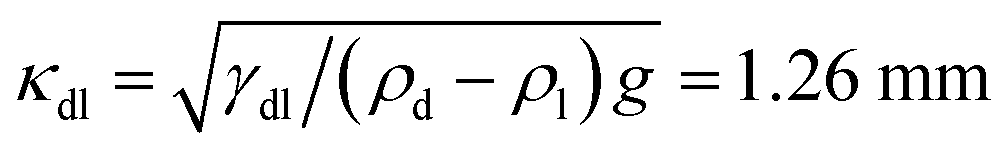 .
.


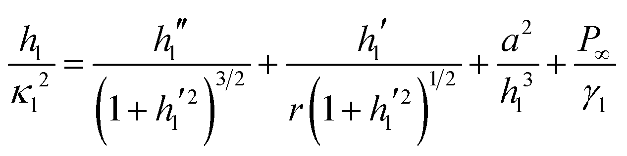
 is the capillary length of the lubricant. The first two terms on the right hand side, hl′′(1 + hl′2)−3/2 + hl′r−1(1 + hl′2)−1/2, represent the curvature of the axisymmetric meniscus shape. The primes denote differentiation with respect to r. The third term on the right hand side takes van der Waals forces into account. The van der Waals length a is related by a2 = AH/6πγl to the Hamaker constant AH for air interacting with the solid support across lubricant. With an estimated Hamaker constant of AH ≈ 2.5 × 10⁻²⁰ J30 we obtain a van der Waals length a = 0.2 nm. P∞ is the effective pressure in the film at substrate level. Because absolute hydrostatic pressures are small, P∞ ≈ Pl.