DOI:
10.1039/C6SM02727J
(Paper)
Soft Matter, 2017,
13, 1823-1833
High-resolution structure of coexisting nanoscopic and microscopic lipid domains†
Received
6th December 2016
, Accepted 29th January 2017
First published on 30th January 2017
Abstract
We studied coexisting micro- and nanoscopic liquid-ordered/liquid-disordered domains in fully hydrated multilamellar vesicles using small-angle X-ray scattering. Large domains exhibited long-range out-of-plane positional correlations of like domains, consistent with previous reports. In contrast, such correlations were absent in nanoscopic domains. Advancing a global analysis of the in situ data allowed us to gain a deep insight into the structural and elastic properties of the coexisting domains, including the partitioning of cholesterol in each domain. In agreement with a previous report, we found that the thickness mismatch between ordered and disordered domains decreased for nanoscopic domains. At the same time, we found also the lipid packing mismatch to be decreased for nano-domains, mainly due to the liquid-disordered domains becoming more densely packed when decreasing their size.
1 Introduction
Biological membranes are well-known to define and control intra- and intercellular environments. One of the most intriguing features of biomembranes is their lateral heterogeneity,1–3 called domains or rafts,4 which have been postulated to be involved in a wide range of physiological processes.5,6 Efforts to provide direct experimental evidence for the existence of membrane rafts have not been without significant controversy,7,8 which is often attributed to their small, nanoscopic size and/or short life-times.9
In contrast, membrane domains are well-established in complex lipid-only mixtures of low- and high-melting lipids and cholesterol (Chol),10 or other sterols which are able to condense saturated hydrocarbons.11,12 Lipid-only domains of so-called liquid ordered (LO) and liquid disordered (LD) phases have been studied by a wide range of experimental techniques, including fluorescence microscopy (see, e.g., ref. 13), Förster resonance energy transfer (FRET) (see, e.g., ref. 14), neutron diffraction,15 small-angle X-ray and neutron scattering (SAXS, SANS),16 or nuclear magnetic resonance (see, e.g., ref. 17). LO domains are considered as archetypes of rafts and their structural and elastic properties are of particular interest for understanding selective protein partitioning.18,19
One of the interesting features of cholesterol-containing raft-like lipid mixtures is the ability to control domain size by lipid composition.20 For example, ternary mixtures with diunsaturated or highly branched lipids as the low-melting component display micron-sized domains, which can be readily observed under a microscope using fluorescent lipid labels (see, e.g., ref. 21). Exchanging the diunsaturated lipids to monounsaturated lipids, like palmitoyloleoylphosphocholine (POPC), instead reduces the size of these domains to a few nanometers.14,22–24 Alternatively, such systems have been proposed to resemble a microemulsion.25 Deciphering the intrinsic structural properties of nanoscopic LO/LD domains is highly challenging. Most recently, Nickels and coworkers26 were able to describe the thickness and bending rigidity of coexisting LO and LD domains in the nanoscopic regime in large unilamellar vesicles (LUVs) applying neutron scattering in combination with contrast variation.
Here, we set out to show that detailed structural and elastic information of nanoscopic lipid domains in multilamellar vesicles (MLVs) can be retrieved from a global SAXS data analysis. Besides domain thickness and thickness of the hydrocarbon chain layer, our analysis is capable of retrieving the maximum bending fluctuation amplitudes of domains, as well as the packing density of lipids and the partitioning of cholesterol in LO/LD domains.
To achieve this goal, we followed the approach of Heftberger et al.,27 who detailed the analysis of coexisting micron-sized domains in MLVs by combining a modified Caillé theory description of the structure factor,28 with a scattering length density profile (SDP) model29 for the form factor. Our modeling led us also to reconsider domain stacking in the microscopic and nanoscopic regimes allowing for contributions of partially anticorrelated domains and overlapping domain leaflets. Additional modifications of our previous modeling included an intrinsic definition of the area per lipid (area per unit cell) and a generic parameterization of cholesterol distribution within the coexisting domains, which allows to extract cholesterol partitioning with high fidelity. Our SDP model for cholesterol differs from previous descriptions27,30 and is applicable for any other additive molecule(s) displaying affinity to either the LD or LO phase. The new model yielded improved results for high-resolution SAXS data on micron-sized domains and gave first insights on the structural properties of LD and LO domains in the nanoscopic regime. Most interestingly, we found that the previously reported decrease of the LO/LD thickness mismatch for nanoscopic domains22 goes hand in hand with a decrease of the lipid packing mismatch.
2 Theory
Following the approach of Heftberger et al.27,31 we adopted the global analysis model of Pabst et al.32,33 to the case of coexisting domains. For completeness and clarity of arguments, we revisit some of the most important arguments leading to an improved model that also captures nanoscopic domains.
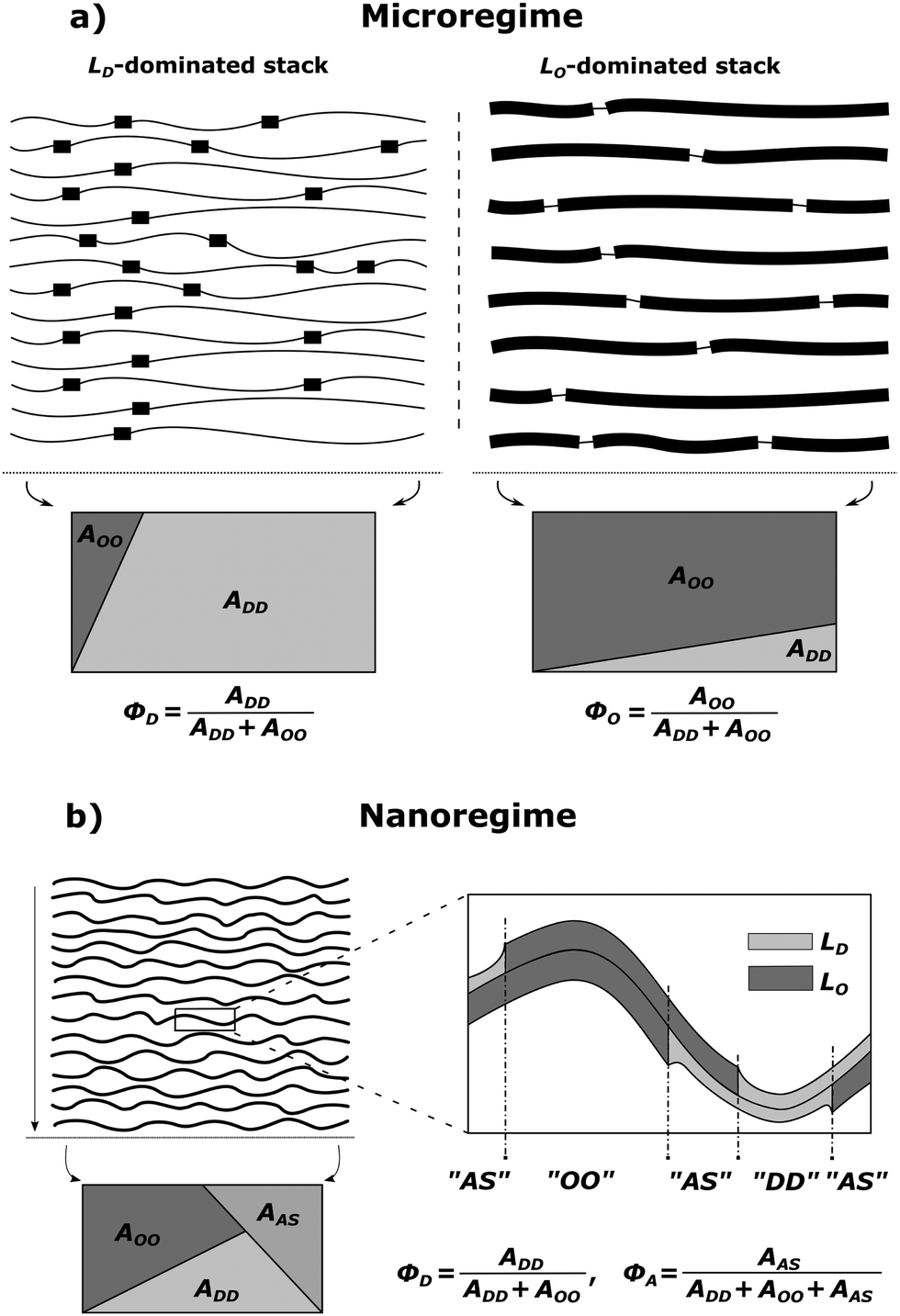
MLVs displaying coexisting domains were considered as stacks of weakly bound bilayers averaged over all possible spatial orientations. Micron-sized domains were shown to exhibit long-range alignment of like domains in the stacking direction (see, e.g., ref. 30, 34 and 35), giving rise to two distinct families of lamellar Bragg lattices, which we consider to be dominated by either LO or LD domains. That is, unlike previous assumptions, we presently also consider contributions from positionally anticorrelated domains, i.e., LO in LD and vice versa (Fig. 1a). The total scattering of such systems is
| | | Itot(q) ≈ lD·ID(q) + lO·IO(q), | (1) |
where
lD and
lO are the volume fractions occupied by the
LD phase and the
LO phase ‘dominated’ stacks (
lD +
lO = 1), respectively,
ID,O(
q) are the scattering intensities of the respective stacks, and
q is the modulus of transferred momentum.
 |
| | Fig. 1 Schematic of domain alignment in the microscopic (a) and the nanoscopic regimes (b) in MLVs. LD domains are represented by thin and LO domains by thick lines, respectively. In the microscopic regime, each stack is dominated by either LD or LO domains, but also contains contributions from unlike domains. Such impurities are taken into account by the purity parameters, ΦD and ΦO, which are based on the surface area fractions of liquid ordered AOO and liquid disordered ADD domains (see also eqn (15)–(18)). The rectangles give a graphical representation of the irradiated surface area within a scattering volume element, which is divided into individual fractions. In the nanoscopic regime, an additional area fraction of leaflet anticorrelated domains AAS needs to be taken into account in the purity parameter ΦD (see text for details). | |
For nanoscopic domains, only a single lamellar lattice is observed (see the Results section). That is, Itot(q) contains contributions from LO and LD domains, but unlike MLVs with micron-sized domains, the interbilayer separation between LO and LD domains is identical (Fig. 1b).
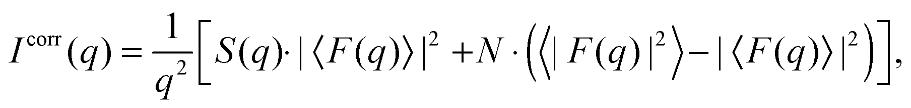
Assuming that the fluctuations within the bilayer are independent of the fluctuations of the lattice points, the scattered intensities of MLVs can be split according to Debye into the structure factor S(q), describing the dynamic positional correlations between the layers and the form factor F(q), which accounts for the transbilayer/domain structure.36 Thus, for scattering from a stack consisting of N positionally correlated bilayers in either the micro- or nanoscopic regime,
| |  | (2) |
where 〈⋯〉 represents averaging through all bilayers within a given stack.
Additional scattering contributions from positionally uncorrelated bilayers/domains, originating, e.g., from defects due to packing mismatches, need to be considered.33 Taking these into account, the full scattering intensity of each stack becomes
| |  | (3) |
where
fdiff gives the fraction due to diffuse scattering. Naturally,
fdiff comprises also of the scattering contributions from unilamellar vesicles, that may be present in the sample.
2.1 Structure factor
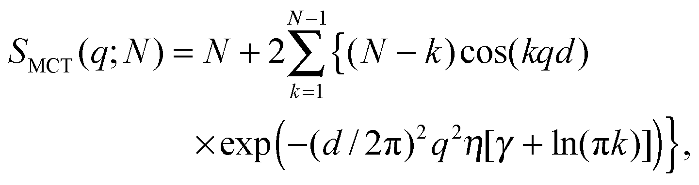
Positional correlations of fluid multibilayers are known to be affected by membrane undulations, which can be described by the modified Caillé theory (MCT).28,37 Within this theory the structure factor for each stack is| |  | (4) |
where N is the number of spatially correlated bilayers per scattering domain, γ is Euler's constant and| |  | (5) |
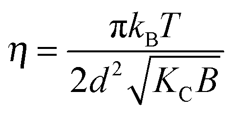
is the Caillé parameter, which is a measure of bilayer fluctuations, that depend on temperature T, the bending rigidity KC and the bulk modulus of the interbilayer interactions, B (kB is Boltzmann's constant).38 From η we can directly calculate the fluctuations in bilayer separation Δfl2 = ηd2/π2.39 The polydispersity of N can be described by different probability distributions.28,37,39,40 Here we chose an exponential probability distribution| |  | (6) |
which is a special case of the well-known Schulz–Flory distribution,41–43 where Nmean is the sample average of N. We also tested a regular Schulz–Flory distribution, but the exponential distribution yielded better fits for all the presently studied systems.
2.2 Form factor
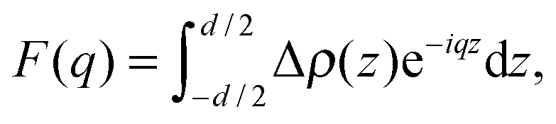
To model the form factor, we have to consider two different scenarios (Fig. 1): (i) leaflet-correlated domains (LO/LO, LD/LD) and (ii) leaflet-anticorrelated domains (LO/LD, LD/LO). Micron-sized domains are well-known to exhibit transbilayer coupling of like domains.44 Thus, only leaflet-correlated domains need to be considered. In the nanoscopic regime, both types of domains may occur as suggested by a recent simulation study.45 In general, the form factor is given by the Fourier transformation of the contrast scattering length density profile Δρ(z) (=ρ(z) − ρs) along the bilayer normal, z,| |  | (7) |
where ρ(z) is the transbilayer electron density and ρs is the electron density of the solvent. Note that leaflet-correlated domains represent a centrosymmetric crystalline system, while leaflet-anticorrelated domains are asymmetric.
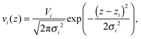
In order to easily differentiate between symmetric and asymmetric systems, we describe the transdomain structure for each leaflet separately. For modeling the internal leaflet structure, we applied the scattering length density profile (SDP) description developed by Kučerka et al.,29,46 which allows to jointly analyze X-ray and neutron scattering data. In the framework of the SDP model, each lipid molecule is parsed into quasi-molecular fragments. For the presently studied lipids, these components are the choline methyl groups (ChoMet), phosphate + CH2CH2N (PCN), glycerol + carbonyls (GC), hydrocarbon methylene groups (HC) and finally the terminal chain methyls (CH3).
The crystallographic unit cell is therefore realized by a single phospholipid molecule, which is in the present experimental case given by an averaged DSPC/DOPC, or DSPC/POPC molecule. Cholesterol is considered as an additive, which is able to distribute into LD and LO phases as discussed in Section 2.3. The base area of this unit cell is an important structural parameter – the interfacial area per lipid molecule A. In the case of lipid mixtures with cholesterol, A also contains a fraction of cholesterol and is therefore referred to as the area per unit cell.47 Naturally this applies to any admixture molecule. Note that this definition differs from the partial lipid areas reported in other studies.48,49 Each individual component of the lipid molecule is represented in the SDP model by its lateral unit fraction ai(z) – a function describing the fractional contribution of a given component to A, requiring that  due to ideal volume filling.
For each leaflet, the contribution of the hydrocarbon chain fraction is described by a single plateau-function
| |  | (8) |
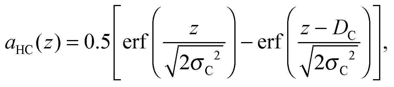
where
DC and
σC are the position and “roughness” of the hydrocarbon chain region interface, respectively, and erf(
x) refers to the error function. In our SDP model, the HC volume
VC contains also a fraction of lipophilic additives,
| |  | (9) |
where
Vchains is the total volume of the phospholipid hydrocarbon chains (
i.e. a mixture of low-melting and high-melting lipids, excluding carbonyl groups), and
Vadm,i is the volume of the
ith lipophilic additive, here given by cholesterol, added with a relative molar ratio of
ri. The calculation of
ri for
LO and
LD domains is detailed in Section 2.3. Because of the assumed conservation of volumes,
DC is coupled to
A through
| |  | (10) |
Thus
A and
DC are interdependent parameters. In the present work, we fitted
A and derived
DC through
eqn (10).
All other quasi-molecular fragments of the unit lipid molecule, i.e., the polar headgroup components and the terminal methyl group, are given by Gaussian probability densities29 with an average volume distribution
| |  | (11) |
where
Vi is the molecular volume of the
ith component (
i = PCN, CG,…),
zi is the center of mass, and
σi is the Gaussian standard deviation. Note that
Vi needs to be scaled by its relative molar ratio
ri according to the concentration of cholesterol (or any admixture molecule in general),
Vi =
ri·
Vi,single, where
Vi,single are the volumes reported for the pure lipid components. The corresponding
ai(
z)'s are then given by
| |  | (12) |
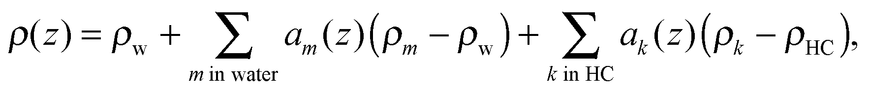
The final transbilayer SDP is constructed by a step-by-step replacement of the homogeneous water (ρw)/hydrocarbon core (ρHC) background in both leaflets by properly scaled individual components (using eqn (12))
| | 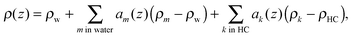 | (13) |
where
ρm,k =
nem,k/
Vm,k are the electron densities of a given quasi-molecular fragment with
nem,k number of total electrons, and
ρHC =
ρCH2. The first sum in
eqn (13) runs through all components within the water environment (including the hydrocarbon chains core) and the second one through all hydrophobic components (
e.g., terminal methyl groups, cholesterol). Because of minute differences in hydrocarbon volumes of the phospholipids studied here, we were not able to deconvolute their contributions. Therefore, the molecular averages of phospholipids in each domain were calculated according to reported compositional phase diagrams.
14,24 Since lipid headgroup volumes do not change significantly with temperature or phase,
50 the volumes and widths of the PC headgroup components were assumed to be the same in both phases. Their values were adopted from the works of Klauda
et al.51 and Kučerka
et al.46 The chain methylenes and methines carry insufficient electron density contrast to be detected by X-rays. We therefore fixed the hydrocarbon chain core widths and coupled their border positions (
DC) to the CG group
zCG =
DC + 0.9 Å using the values obtained by Kučerka
et al.46
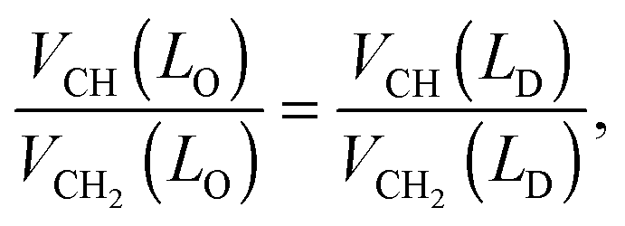
The hydrocarbon chain volumes were calculated using the data reported in ref. 50 and 52, assuming that
| | 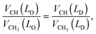 | (14) |
and that
VCH2(
LO) equals the value reported for the gel phase (see Table S2 in the ESI
†). Further, we assumed
VCH3 = 2
VCH2 in the
LD-phase,
50 while
VCH3 was an adjustable parameter in the
LO domains.
In order to describe the scattering of microscopic or nanoscopic domains in MLVs, we now need to consider contributions from ‘impurities’. In the case of micron-sized domains, these originate from unlike domains such as LO in LD dominated stacks and vice versa (Fig. 1a). The average area fraction of each domain in each stack is described by the purity Φi (ΦD,ΦO). For definition, see Fig. 1. The amplitudes of the averaged form factors and their averaged squared amplitudes in eqn (2) and (3) then become
| |〈FD(q)〉| = |ΦDFD(q) + (1 − ΦD)FO(q)|, |
| | | |〈FO(q)〉| = |ΦOFO(q) + (1 − ΦO)FD(q)|, | (15) |
and
| 〈|FD(q)|2〉 = ΦD|FD(q)|2 + (1 − ΦD)|FO(q)|2, |
| | | 〈|FO(q)|2〉 = ΦO|FO(q)|2 + (1 − ΦO)|FD(q)|2. | (16) |
In the case of nanoscopic domains, we do not find long-range alignment of like domains (see Section 4.2), but need to consider contributions from leaflet-anticorrelated domains (Fig. 1b). Thus, we have scattering from symmetric (LO/LO, LD/LD) and asymmetric domains (LO/LD, LD/LO). Since we have no measure for the orientation of the asymmetric domains, we assume that half of the asymmetric domains are LO/LD and the other half LD/LO. Defining the area fraction of asymmetric domains, ΦA, as illustrated in Fig. 1b, we find the form factor amplitudes of nanoscopic domains
| | | |〈Fnn(q)〉| = |ΦAFA(q) + (1 − ΦA)(ΦDFD(q) + (1 − ΦD)FO)| | (17) |
and
| | | 〈|Fnn(q)|2〉 = ΦA|FA(q)|2 + (1 − ΦA)(ΦD|FD(q)|2 + (1 − ΦD)|FO(q)|2), | (18) |
where
FD(
q), and
FO(
q) are the form factors of symmetric
LD or
LO domains, respectively, and
FA(
q) is the form factor of asymmetric domains.
2.3 Partitioning of cholesterol
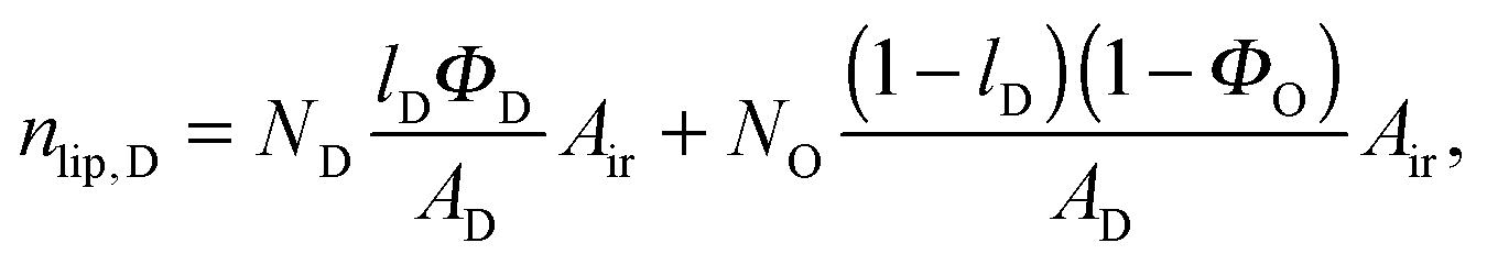
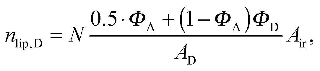
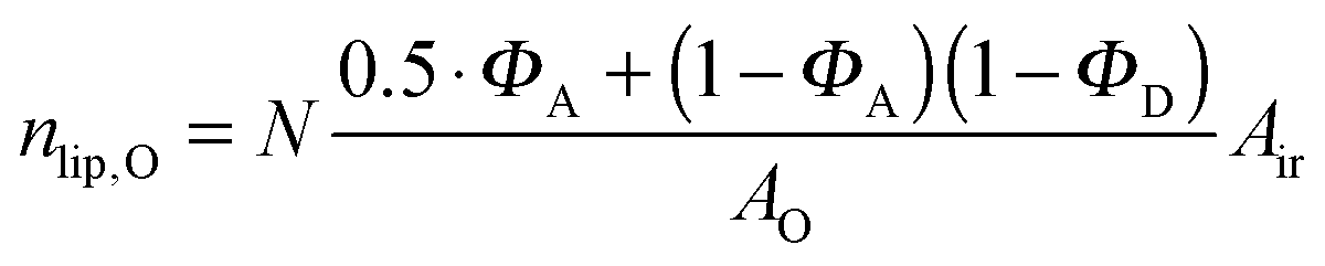
The effect of cholesterol (and any other added lipophilic molecule) on the scattering curve depends not only on the overall surface coverage of a given domain, but even more crucially on its molar ratio/fraction within LO or LD. Thus, the cholesterol content of a given domain can be determined from scattering experiments. Recently, Ma et al.53 estimated cholesterol partitioning in LD/LO domains by fitting Gaussian-like functions to electron density profiles, assuming that the observed profile changes originate only from the added electron densities of cholesterol.
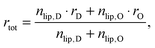
Here, we introduce an alternative approach, which does not rely on the above mentioned assumption. The relative molar ratios of cholesterol in LD and LO domains (rD, rO) can be decoupled from the overall molar ratio of cholesterol in the lipid mixture rtot = nchol/nlip, where nchol and nlip are the total molar numbers of cholesterol and phospholipid per sample, by considering
| |  | (19) |
with
| |  | (20) |
| |  | (21) |
in the microscopic regime (see
eqn (1) for the definition of
lD) and
| |  | (22) |
| |  | (23) |
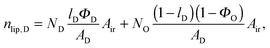
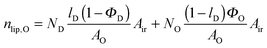
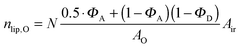
in the nanoscopic regime. Here,
Air is the average irradiated surface area of a single sheet within a given stack of bilayers,
AD/
AO are the areas of the unit cells in the
LD/
LO domains, and
ND/
NO are the average numbers of positionally correlated bilayers in each stack.
Inserting eqn (20) into eqn (19) and eqn (22) into eqn (21) allows Air to be removed and one obtains after some arithmetic
| | | rO = rtot + (rtot − rD)·Γ, | (24) |
where
| | 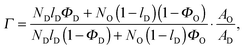 | (25) |
for the microscopic regime and
| |  | (26) |
for the nanoscopic regime, which were used to evaluate
eqn (9). Specifically, we fitted
rD and calculated
rO using the equations above. Heftberger
et al.27 used a similar model, but fitted
rD and
rO independently.
The molecular volume of cholesterol in LD domains VChol(LD) = 628 Å3 was supplied from volumetric measurements of DOPC/Chol mixtures.54 In turn, VChol is not known for LO domains. We therefore decided to vary VChol(LO) between its known extremes in binary mixtures.50 In most cases, the final value of VChol(LO) ended up between 600 Å3 and 650 Å3.
In each domain, cholesterol is parsed into a head and acyl tail group.55 We further assumed that the electron density of the acyl tail group ρtChol = ρHC, from which we calculate the corresponding volume VtChol = nte/ρtChol, with nte being the number of electrons of the cholesterol tail. The cholesterol head group volume is simply derived from VChol = VhChol + VtChol. The cholesterol head group is represented by a Gaussian-like aChol(z) (12).
2.4 Domain thickness
For comparison to other structural data, we define the Luzzati thickness as a measure for the thickness of the domains as56| |  | (27) |
where VL and Vadm are the total volumes of the mixed phospholipid molecule and the admixture molecule (here cholesterol), respectively, and ri is the relative molar ratio of the admixture in a given domain. Alternatively, the head-to-head distance of a given domain is defined as the cross-bilayer distance between the PCN groups
3 Materials and methods
3.1 Chemicals
POPC, DOPC and DSPC were purchased from Avanti Polar Lipids (Alabaster, AL, USA) and cholesterol from Sigma-Aldrich (Vienna, Austria) as dry powders. All lipids were used without any further purification. Organic solvents of spectral purity were obtained from Lactan (Graz, Austria) and Milli-Q water (18 MΩ cm at 25 °C) was freshly prepared before use.
3.2 Sample preparation
Dispersions of fully hydrated MLVs were prepared by rapid solvent exchange (RSE) as detailed by Rieder et al.57 Briefly, first stock solutions were prepared by dissolving weighted amounts of lipid in a methanol/chloroform (1/9) solvent. Lipid concentration was determined to <1% by inorganic phosphate assay.58 Lipid mixtures of POPC![[thin space (1/6-em)]](https://www.rsc.org/images/entities/char_2009.gif) :DSPC:Chol = 0.39:0.39:0.22 and DOPC:DSPC:Chol = 0.46:0.3:0.24 were obtained by mixing appropriate amounts of the stock solutions. Then 300 μl of each solution was transferred into a test tube containing 600 μl Milli-Q water using a gastight Hamilton syringe. The test tube was mounted onto the RSE apparatus and heated under a constant stream of argon to 70 °C (above the boiling points of methanol and chloroform). This allowed fast evaporation of the organic solvent without the need of negative pressure. Each mixture was evaporated for 12 minutes. During evaporation, samples were constantly vortex-mixed at 1000 rpm to prevent sedimentation of methanol–chloroform solution droplets as well as to increase their evaporation rate. The final lipid concentration in each sample was at least 30 mg ml−1.
:DSPC:Chol = 0.39:0.39:0.22 and DOPC:DSPC:Chol = 0.46:0.3:0.24 were obtained by mixing appropriate amounts of the stock solutions. Then 300 μl of each solution was transferred into a test tube containing 600 μl Milli-Q water using a gastight Hamilton syringe. The test tube was mounted onto the RSE apparatus and heated under a constant stream of argon to 70 °C (above the boiling points of methanol and chloroform). This allowed fast evaporation of the organic solvent without the need of negative pressure. Each mixture was evaporated for 12 minutes. During evaporation, samples were constantly vortex-mixed at 1000 rpm to prevent sedimentation of methanol–chloroform solution droplets as well as to increase their evaporation rate. The final lipid concentration in each sample was at least 30 mg ml−1.
3.3 Measurements
The SAXS scattering curves were obtained either at the ESRF BM29 BioSAXS beamline59 (Grenoble, France) or at the P12 SAXS beamline60 at DESY (Hamburg, Germany). At BM29, the samples were measured at an X-ray wavelength of λ = 0.99 Å using a sample-detector distance (SDD) of 2.869 m, whereas the experiments at the P12 beamline were performed at λ = 0.6 Å and SDD = 3.1 m. Scattered intensities were recorded using a Pilatus 1M (BM29), or a Pilatus 2M (P12) detector (Dectris, Baden, Switzerland).
At both beamlines, the samples were transferred prior to measurement into multi-well plates and equilibrated for 10 minutes in a temperature-controlled block. An automated sample robot delivered 20–35 μl of the lipid sample into a preheated glass capillary. For each sample, 20 frames were recorded with an exposure time of 0.095 s at P12 and 10 frames, each with 1 s exposure, at BM29. Water background was measured before and after each sample. To avoid introductions of artifacts by radiation damage, the data collected in subsequent frames were compared and rejected in case of statistically significant deviations. Background subtraction was performed by using the ATSAS software suite.61
3.4 Model evaluation
The final form of the model function for the microscopic regime is| | | Itot(q) = K·(lD·Id,diff(q) + (1 − lD)·Io,diff(q)) + Ibckg | (29) |
and for the nanoscopic regime| | | Itot(q) = K·Inn,diff(q) + Ibckg, | (30) |
where K is a scaling constant and Ibckg is the flat background intensity originating from incoherent scattering. The fitting was achieved by minimizing| |  | (31) |
where Iexp,i are the measured intensities and ΔIexp,i their uncertainties. The overall large number of model parameters bear the potential of over-fitting, which needs to be addressed carefully. Our strategy was to fix or constrain as many parameters as possible using data from previous scattering studies applying a SDP analysis and complementary techniques, such as dilatometry. In particular, we fixed (i) the widths and (ii) the relative positions of all headgroup Gaussians (PCN, ChoMet) with respect to the GC-group, using values obtained by Kučerka et al.46 and (iii) set the distance between the GC-group and the water-chains interface (zCG–DC) to 0.9 Å, capturing its reported range of 0.8–1 Å.46 Further details of the used parameters and the underlying assumptions were discussed in the previous section. All parameters supplied from previous measurements are summarized in Table S2 (ESI†).
The remaining overall number of adjustable parameters varied between 18 in the microscopic regime and 13 in the nanoscopic one. The application of a global search algorithm was therefore necessary in order to avoid getting stuck in a local minimum during optimization. More specifically, optimization was carried out by the combination of the differential evolution algorithm62 and the minimization and error analysis library MINUIT2 (CERN Program Library entry D506, utilizing the Levenberg–Marquardt algorithm).
4 Results and discussion
Prior to applying our model to coexisting domains, we tested its capabilities on well-studied single component bilayers of pure DOPC. Our best fit agreed well with the scattering data obtained at 20 °C over the whole q-range. The resulting structural parameters are detailed in Table S1 (ESI†) and the corresponding fit is plotted in Fig. S1 (ESI†).
Comparing to literature values, we focus, in particular, on the lateral area per lipid. From our analysis we obtained A = 64.3 Å2, which agrees favorably with A = 66.9 Å263 and A = 67.6 Å2,31 both obtained at 30 °C, considering the lateral expansion of the bilayer with temperature.46 We therefore conclude that our model successfully captures high-resolution structural information of single component bilayers also. For further structural results of DOPC, see the ESI.†
4.1 Microscopic domains
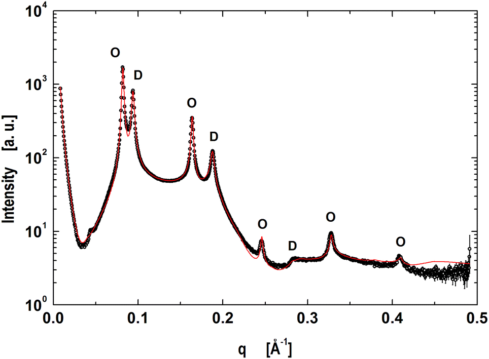
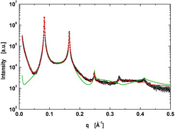
The next step was to evaluate the model for micron-sized domains, which have been shown to exhibit long-range out-of-plane domain alignment in multibilayers and which have been analyzed in terms of a global SAXS data analysis before.27,64 Thus our system of choice was the above detailed mixture of DOPC/DSPC/Chol (0.46/0.3/0.24).65 The corresponding data shown in Fig. 2 clearly show the presence of two coexisting lamellar lattices, where the higher d-spacing phase (76.7 Å) is ascribed to the LO-dominated stacks, implying that the lattice of d = 66.9 Å corresponds the LD-dominated stacks. These values are in excellent agreement with our previous report.27
 |
| | Fig. 2 Global analysis (red line) of microscopically phase separated DOPC/DSPC/Chol multibilayers. Peaks corresponding to LD dominated stacks are indicated by ‘D's’ and ‘O's’ correspond to the lamellar lattice of LO dominated stacks. | |
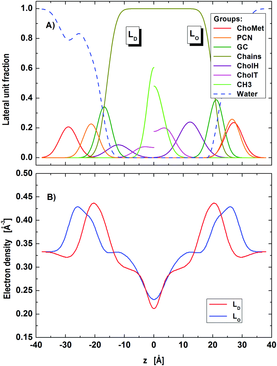
Our model is able to fit the data well up to q < 0.4 Å−1. Discrepancies for q > 0.4 Å−1 are most probably caused by subtle structural features of the LO polar headgroup region, which we currently do not capture. The resulting group distribution functions of the LD and LO phases and the corresponding electron density profiles are presented in Fig. 3.
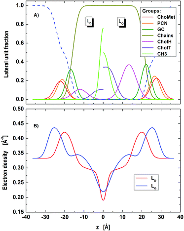 |
| | Fig. 3 Distribution of component groups (A) and corresponding electron density profiles (B) of DOPC/DSPC/Chol LD and LO domains in the microscopic regime. | |
Lattice parameters obtained from our detailed analysis (Table 1) show that about two thirds of the sample (lD = 0.675) was composed of LD dominated stacks. Looking at the abundance of each phase we found that LD-stacks were somewhat ‘purer’ in LD domains (ΦD = 93.6%) than LO stacks in LO domains (ΦO = 73.1%).
Table 1 MLV lattice structure parameters in the microscopic regime. Parameter uncertainties are <2%
| Parameter |
Bilayer lattice |
|
L
D-dominated |
L
O-dominated |
|
l
i
|
0.67 |
0.33 |
|
Φ
i
|
0.94 |
0.73 |
|
d [Å] |
66.9 |
76.6 |
|
η × 10−2 |
13.4 |
3.3 |
|
Δ
fl [Å] |
7.8 |
4.5 |
|
N
bil
|
10.5 |
10.9 |
The relative molar ratios of cholesterol were found to be rO = 0.493 in LO domains and rD = 0.208 in LD domains. These data compare well with rD = 0.205 and rO = 0.471 reported for the same tie-line from FRET studies by Heberle et al.,14 lending strong support to the applied modeling. We emphasize that the obtained results for rD and rO were stable without the need to apply constraints.
Bending fluctuations were significantly lower in LO domains, i.e. by a factor of ∼1.75, than in LD domains. This is consistent with an increased content of DSPC and cholesterol in LO65 that leads to an increase in bending rigidity.66,67 Note, however, that our reported bending fluctuations are a function of bending rigidity and interactions across the aqueous phase (eqn (5)). That is, the decrease of η for LO domains may also be due to an increase of interactions. This can be illustrated using eqn (5) and assuming that B is equal for both domains. A detailed interaction analysis of the same system using osmotic stress reported that LO domains are almost three times more rigid than LD domains.64 Using this information we then calculate that η for LD domains should be about two times larger than for LO domains. However, our experimentally determined η values differ by a factor of four (Table 1), signifying that the smaller fluctuations of LO domains are partially also due to increased interactions.
Our η values were systematically larger than reported previously.27 This can be attributed to the presently higher experimental resolution and the improved model description. Interestingly, the bending fluctuations of LD domains, which are rich in DOPC, are significantly higher (factor: ∼2.4) than those of pure DOPC MLVs (see Table S1, ESI†), despite the fact that they contain some cholesterol. This might be due to local bilayer thinning defects at the domain boundaries as suggested by Nickels et al.,26 leading to increased domain fluctuation amplitudes.
Turning to the domain structure (Table 2) and comparing with our previous report,27 the new A values are somewhat higher for both domains (LD: A = 69.5 Å2vs. 60.3 Å2 and LO: A = 57.4 Å2vs. 43.1 Å2), especially for LO. We believe, that the discrepancies are mainly caused by different ways of calculating A. Here, we fitted A assuming volume conservation of the hydrocarbon core, considering also the contributions from cholesterol, while Heftberger et al.27 calculated A by finding the Luzzati thickness from the water distribution function. Further, the improved quality of data and model fits may also explain the observed differences. The increase of A in LD domains, with respect to pure DOPC (Table S1, ESI†) is due to the fraction of cholesterol contributing to the unit cell, consistent with a previous report on binary mixtures with cholesterol.47 Defining the average lateral area per molecule as Am = A/nm, where nm is the number of molecules per unit cell (including both PCs and Chol), we find a tighter packing of the molecules in both domains (AmD = 57.5 Å2vs. AmO = 38.4 Å2) as compared to pure DOPC, which naturally agrees with the commonly accepted lateral membrane condensation property of cholesterol. The lower A-value of LO domains as compared to LD domains is consistent with an enrichment in cholesterol and DSPC.
Table 2 Structural parameters of LD and LO domains in the microscopic regime. Parameter uncertainties are <2%
| Parameter |
Microdomains |
|
L
D domains |
L
O domains |
|
A [Å2] |
69.5 |
57.4 |
|
A
m [Å2] |
57.5 |
38.4 |
|
D
C [Å] |
16.0 |
21.2 |
|
D
B [Å] |
41.5 |
53.9 |
|
D
HH [Å] |
42.6 |
53.4 |
|
z
GC [Å] |
16.9 |
22.2 |
|
z
PCN [Å] |
21.3 |
26.7 |
|
r
Chol,i
|
0.208 |
0.493 |
|
z
Chol [Å] |
12.1 |
13.3 |
|
σ
CH3 [Å] |
1.94 |
2.63 |
Because DC is coupled to A (eqn (10)), our hydrocarbon core thickness values are smaller than reported previously (∼2 Å for LD and ∼5 Å for LO).27 However, when comparing the Luzzati thicknesses, these differences are minimal, in particular for LO domains (present: DB(LD) = 41.5 Å, DB(LO) = 53.9 Å; Heftberger et al.:27DB(LD) = 39.2 Å, DB(LO) = 49.2 Å) and almost agree within the experimental resolution.
Finally, the average positions of the cholesterol headgroup were almost identical in both phases, zChol(LD) = 12.1 Å and zChol(LO) = 13.3 Å, which is in good agreement with our previous report using a simpler parsing description for cholesterol.27
4.2 Nanoscopic domains
Nanoscopic domains in POPC/DSPC/Chol (0.39/0.39/0.22), did not exhibit long-range out-of-plane positional correlations of like domains, but displayed only a single lamellar lattice (Fig. 4) with a d-value of 75.9 Å, i.e. very close to the d of micron-sized LO domains (Table 1). To exclude the possibility of the randomly-mixed bilayers, we also carried out a corresponding single phase fit. However, even the best single phase fit, for which we also tried to release some of the volumetric constraints, was not able to follow the scattering curve (Fig. 4). In particular, the homogeneous model fails to account for the observation that minima of the scattered intensity are not on the same level. This is due to the fact that the form factor of a homogeneous bilayer needs to pass through zero, which is not necessarily the case for a heterogeneous bilayer with a mixed form factor (see, e.g., eqn (15)–(18)). Note, however, that we have demonstrated previously, that non-phase-separated mixtures of phospholipids with cholesterol are well-described by a homogeneous model.27,31 This encouraged us to utilize the model for coexisting nanoscopic domains.
 |
| | Fig. 4 Global analysis (red line) of coexisting nanoscopic domains in POPC/DSPC/Chol multibilayers. The green line shows the best fit assuming homogeneous lipid mixing. | |
During fitting with the nanoscopic domain model, we found instabilities of the optimization primarily in cholesterol related parameters (position, concentration). This is most likely due to the small contrast between nanoscopic LO and LD domains for X-rays. Further exploitation of this issue requires a joint analysis of differently contrasted SANS data with the SAXS data of nanoscopic domains. Such studies are currently being planned in our laboratory. Note that the presently described analysis is capable of performing this analysis without any further modification. To analyze current SAXS data, we tested different sets of different structural and volumetric constraints for cholesterol. The best stable fit was obtained upon fixing (i) the relative cholesterol molar ratios (rD = 0.14, rO = 0.34) according to reported tie-line endpoints of the same mixture,65 (ii) the relative positions of cholesterol to GC-groups, ΔzChol,i = zGC,i − zChol,i, to the values obtained in the microscopic regime (ΔzChol,D = 4.8 Å, ΔzChol,O = 8.9 Å), and (iii) the cholesterol molecular volumes (VChol,D = VChol,O = 630 Å3) in agreement with the results obtained by Heberle et al.65 The resulting fit and domain structure are shown in Fig. 4 and 5, the corresponding model parameters are summarized in Tables 3 and 4.
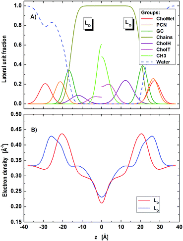 |
| | Fig. 5 Distribution of component groups (A) and corresponding electron density profiles (B) of POPC/DSPC/Chol LD and LO domains in the nanoscopic regime. | |
Table 3 MLV lattice structure parameters in the nanoscopic regime. Parameter uncertainties are <2%
| Parameter |
Bilayer lattice |
|
Φ
D
|
0.32 |
|
Φ
A
|
0.023 |
|
d [Å] |
75.9 |
|
η × 10−2 |
4.9 |
|
Δ
fl [Å] |
5.3 |
|
N
bil
|
16.8 |
Table 4 Structural parameters of LD and LO domains in the nanoscopic regime. Parameter uncertainties are <2%
| Parameter |
Nanodomains |
|
L
D domains |
L
O domains |
|
Fixed values.
|
|
A [Å2] |
64.1 |
56.3 |
|
A
m [Å2] |
56.2 |
42.0 |
|
D
C [Å] |
15.9 |
20.2 |
|
D
B [Å] |
42.2 |
52.1 |
|
D
HH [Å] |
42.6 |
53.1 |
|
z
GC [Å] |
16.9 |
21.1 |
|
z
PCN [Å] |
21.3 |
26.5 |
|
r
Chol,i
|
0.14 |
0.34 |
|
z
Chol
[Å] |
12.1 |
12.3 |
|
σ
CH3 [Å] |
2.3 |
3.2 |
Regarding the lattice parameters (Table 3) we found that the bending fluctuations, η, and their amplitudes, Δfl, are close to those in micron-sized LO domains. This is consistent with LD domains being less abundant than LO domains, as obtained from our analysis (ΦD = 32%). The latter value is also in agreement with the reported compositional phase diagram.14 Interestingly, the found fraction of leaflet anti-correlated domains is small (ΦA ∼ 1%). Nevertheless, ΦA has a significant effect on the scattered intensity. That is, setting ΦA = 0 does not produce a satisfactory fit of the SAXS pattern.
The observation of only a single lattice might also be connected to the beam's coherence length, ξ. In general ξ is a function of the beamline geometry (transversal coherence length) and the energy bandwidth (longitudinal coherence length).16,68 Specifically, ξ influences the weight given to the scattering of the individual lattices of ‘pure’ like domains and their cross interference. That is, ‘pure’ terms become dominant if the characteristic length of positional correlations of like domains is on the order of ξ (or larger). In this case, we would observe two lattices as in the case of micron-sized domains. Likewise, interference term(s) become dominant, if the characteristic length of positional correlations of domains is significantly smaller than ξ. Typical coherence lengths at synchrotron sources are on the order of a few microns. Thus, the single d-value found for nanoscopic domains could well be related to this effect. However, these considerations require that the two lattices have distinct d-values. We are currently not able to discern the different possible organizations of nanoscopic domains. Neutron diffraction experiments, analogous to those performed on dipalmityol phosphatidylcholine bilayers in the phase transition region68 might be useful to shed some light on this issue.
Regarding the domain structure, we did also observe changes compared to micron-sized domains (Table 4; for corresponding electron densities and component distribution functions, see Fig. 5). For example, the area per lipid of LD domains reduced by about 7%, while AO decreased by about 2% only. That is, the mismatch in the packing of lipids between LD and LO, ΔA = |AD − AO| domains becomes much less expressed for nanoscopic domains (ΔAnano ∼ 8 Å2, ΔAmicro ∼ 12 Å2). This may at least in part be due to the different composition of the presently studied nanoscopic LD domains, which with POPC as the dominant species contain a lipid that has a smaller area per lipid than DOPC, enriched in ‘our’ micron-sized LD domains.46,69
Focusing on the transdomain structure, we see the strongest changes to be a decrease in DC by ∼1.0 Å and in DB by ∼1.8 Å for LO domains, whereas the thickness changes in LD were significantly smaller. This yields in total a smaller thickness difference between the LO and LD domains (ΔDB = DB(LO) − DB(LD)) in the nanoscopic regime, when compared to the microscopic one (ΔDnanoB ∼ 10 Å, ΔDmicroB ∼ 12 Å), which is consistent with a previous report.22 Differences to previously reported absolute values of DB22,26 may be due to different model descriptions for the scattering length densities.
5 Conclusions
In the present paper, we have advanced our previously reported SDP model27 for in situ studies of coexisting lipid domains in multibilayers. The presented model accounts for defects induced by positionally anticorrelated domains in micron-sized domains coexisting in MLVs. For nanoscopic domains, no long-range alignment of like domains along the stacking direction was observed. However, modeling had to account for contributions from overlapping/asymmetric domains (LD/LO, LO/LD), which was inspired by a recent simulation report.45 Our modeling allowed us to capture a range of structural details, e.g. area per unit cell, domain thickness, etc., of coexisting microscopic and nanoscopic domains. We note that the here presented model does not capture in-plane scattering of domains. Such scattering is expected to occur at very low q-ranges and has been observed previously using SANS in combination with contrast variation.22 SAXS is rather insensitive to in-plane domain scattering, which allowed us to neglect this contribution.
We found distinct differences in lipid packing densities and domain thicknesses in micron-sized domains in agreement with previous results.27 These differences were found to be less expressed for nano-sized lipid domains, signifying a decrease of thickness mismatch between LD and LO, in agreement with a previous neutron scattering study.22 Here, we also found that the packing of lipids becomes more alike, in particular by laterally more condensed nanoscopic LD domains. For micron-sized domains, our analysis allowed us to determine cholesterol partitioning in LO and LD phases, which agreed well with published data from compositional phase diagrams.
We emphasize that deriving these structural details did neither involve the use of any labels, nor require measuring samples at tieline endpoints. Future studies will be extended to an SDP-based joint neutron and X-ray data analysis to fully exploit contrast variation, analogous to several previous reports on homogeneous lipid bilayers systems.16,70 This will allow us to test the results obtained from current modeling and enable us to determine cholesterol content in nanoscopic domains.
Acknowledgements
The authors are indebted to Frederick A. Heberle for valuable discussions and critical reading of the manuscript. The authors further thank Clément Blanchet (EMBL Hamburg) and Adam Round (ESRF) for technical assistance. The research leading to these results has received funding from the Austrian Science Funds (FWF), project number I1304-B20 (to GP) and the European Community's Seventh Framework Programme (FP7/2007–2013) under BioStruct-X (grant agreement no. 6042.12). Measurements at BM29 were supported through the Austrian BAG proposal MX-1740.
References
- K. Gaus, E. Gratton, E. P. W. Kable, A. S. Jones, I. Gelissen, L. Kritharides and W. Jessup, Proc. Natl. Acad. Sci. U. S. A., 2003, 100, 15554–15559 CrossRef CAS PubMed.
- T. Baumgart, A. T. Hammond, P. Sengupta, S. T. Hess, D. A. Holowka, B. A. Baird and W. W. Webb, Proc. Natl. Acad. Sci. U. S. A., 2007, 104, 3165–3170 CrossRef CAS PubMed.
- D. Lingwood, J. Ries, P. Schwille and K. Simons, Proc. Natl. Acad. Sci. U. S. A., 2008, 105, 10005–10010 CrossRef CAS PubMed.
- K. Jacobson, O. G. Mouritsen and R. G. W. Anderson, Nat. Cell Biol., 2007, 9, 7–14 CrossRef CAS PubMed.
- K. Simons and D. Toomre, Nat. Rev. Mol. Cell Biol., 2000, 1, 31–39 CrossRef CAS PubMed.
- D. Lingwood and K. Simons, Science, 2010, 327, 46–50 CrossRef CAS PubMed.
- M. L. Kraft, Mol. Biol. Cell, 2013, 24, 2765–2768 CrossRef CAS PubMed.
- E. Sevcsik, M. Brameshuber, M. Fölser, J. Weghuber, A. Honigmann and G. J. Schütz, Nat. Commun., 2015, 6, 6969 CrossRef CAS PubMed.
- L. J. Pike, J. Lipid Res., 2006, 47, 1597–1598 CrossRef CAS PubMed.
- D. Marsh, Biochim. Biophys. Acta, Biomembr., 2009, 1788, 2114–2123 CrossRef CAS PubMed.
- H. M. McConnell and A. Radhakrishnan, Biochim. Biophys. Acta, Biomembr., 2003, 1610, 159–173 CrossRef CAS.
- S. A. Pandit, D. Bostick and M. L. Berkowitz, Biophys. J., 2004, 86, 1345–1356 CrossRef CAS PubMed.
- L. A. Bagatolli and E. Gratton, Biophys. J., 2000, 78, 290–305 CrossRef CAS PubMed.
- F. A. Heberle, J. Wu, S. L. Goh, R. S. Petruzielo and G. W. Feigenson, Biophys. J., 2010, 99, 3309–3318 CrossRef CAS PubMed.
- C. L. Armstrong, D. Marquardt, H. Dies, N. Kučerka, Z. Yamani, T. A. Harroun, J. Katsaras, A.-C. Shi and M. C. Rheinstädter, PLoS One, 2013, 8, e66162 CAS.
- D. Marquardt, F. A. Heberle, J. D. Nickels, G. Pabst and J. Katsaras, Soft Matter, 2015, 11, 9055–9072 RSC.
- S. L. Veatch, I. V. Polozov, K. Gawrisch and S. L. Keller, Biophys. J., 2004, 86, 2910–2922 CrossRef CAS PubMed.
- M. Gandhavadi, D. Allende, A. Vidal, S. Simon and T. McIntosh, Biophys. J., 2002, 82, 1469–1482 CrossRef CAS PubMed.
- M. Frewein, B. Kollmitzer, P. Heftberger and G. Pabst, Soft Matter, 2016, 12, 3189–3195 RSC.
- G. W. Feigenson, Biochim. Biophys. Acta, Biomembr., 2009, 1788, 47–52 CrossRef CAS PubMed.
- S. L. Veatch, K. Gawrisch and S. L. Keller, Biophys. J., 2006, 90, 4428–4436 CrossRef CAS PubMed.
- F. A. Heberle, M. Doktorova, S. L. Goh, R. F. Standaert, J. Katsaras and G. W. Feigenson, J. Am. Chem. Soc., 2013, 135, 14932–14935 CrossRef CAS PubMed.
- I. V. Ionova, V. A. Livshits and D. Marsh, Biophys. J., 2012, 102, 1856–1865 CrossRef CAS PubMed.
- T. M. Konyakhina, J. Wu, J. D. Mastroianni, F. A. Heberle and G. W. Feigenson, Biochim. Biophys. Acta, Biomembr., 2013, 1828, 2204–2214 CrossRef CAS PubMed.
- M. Schick, Phys. Rev. E: Stat., Nonlinear, Soft Matter Phys., 2012, 85, 031902 CrossRef CAS PubMed.
- J. D. Nickels, X. Cheng, B. Mostofian, C. Stanley, B. Lindner, F. A. Heberle, S. Perticaroli, M. Feygenson, T. Egami, R. F. Standaert, J. C. Smith, D. A. A. Myles, M. Ohl and J. Katsaras, J. Am. Chem. Soc., 2015, 137, 15772–15780 CrossRef CAS PubMed.
- P. Heftberger, B. Kollmitzer, A. A. Rieder, H. Amenitsch and G. Pabst, Biophys. J., 2015, 108, 854–862 CrossRef CAS PubMed.
- R. Zhang, R. M. Suter and J. F. Nagle, Phys. Rev. E: Stat. Phys., Plasmas, Fluids, Relat. Interdiscip. Top., 1994, 50, 5047–5060 CrossRef CAS.
- N. Kučerka, J. F. Nagle, J. N. Sachs, S. E. Feller, J. Pencer, A. Jackson and J. Katsaras, Biophys. J., 2008, 95, 2356–2367 CrossRef PubMed.
- L. Chen, Z. Yu and P. J. Quinn, Biochim. Biophys. Acta, Biomembr., 2007, 1768, 2873–2881 CrossRef CAS PubMed.
- P. Heftberger, B. Kollmitzer, F. A. Heberle, J. Pan, M. Rappolt, H. Amenitsch, N. Kučerka, J. Katsaras and G. Pabst, J. Appl. Crystallogr., 2014, 47, 173–180 CAS.
- G. Pabst, M. Rappolt, H. Amenitsch and P. Laggner, Phys. Rev. E: Stat. Phys., Plasmas, Fluids, Relat. Interdiscip. Top., 2000, 62, 4000–4009 CrossRef CAS.
- G. Pabst, R. Koschuch, B. Pozo-Navas, M. Rappolt, K. Lohner and P. Laggner, J. Appl. Crystallogr., 2003, 36, 1378–1388 CrossRef CAS.
- S. Karmakar, B. Sarangi and V. Raghunathan, Solid State Commun., 2006, 139, 630–634 CrossRef CAS.
- L. Tayebi, Y. Ma, D. Vashaee, G. Chen, S. K. Sinha and A. N. Parikh, Nat. Mater., 2012, 1074–1080 CAS.
-
A. Guinier, X-ray Diffraction, W. H. Freeman & Co., San Francisco, 1963 Search PubMed.
- R. Zhang, S. Tristram-Nagle, W. Sun, R. L. Headrick, T. C. Irving, R. M. Suter and J. F. Nagle, Biophys. J., 1996, 70, 349–357 CrossRef CAS PubMed.
-
P. G. de Gennes and J. Prost, The Physics of Liquid Crystals, Oxford University Press, Oxford, New York, 2nd edn, 1993 Search PubMed.
-
H. I. Petrache, PhD thesis, Carnegie Mellon University, Pensilvania, USA, 1998.
- T. Frühwirth, G. Fritz, N. Freiberger and O. Glatter, J. Appl. Crystallogr., 2004, 37, 703–710 CrossRef.
- S. R. Aragon and R. Pecora, J. Chem. Phys., 1976, 64, 2395 CrossRef CAS.
- P. Bartlett and R. H. Ottewill, J. Chem. Phys., 1992, 96, 3306 CrossRef CAS.
- J. Pencer, S. Krueger, C. P. Adams and J. Katsaras, J. Appl. Crystallogr., 2006, 39, 293–303 CrossRef CAS.
- M. C. Blosser, A. R. Honerkamp-Smith, T. Han, M. Haataja and S. L. Keller, Biophys. J., 2015, 109, 2317–2327 CrossRef CAS PubMed.
- P. W. Fowler, J. J. Williamson, M. S. P. Sansom and P. D. Olmsted, J. Am. Chem. Soc., 2016, 11633–11642 CrossRef CAS PubMed.
- N. Kučerka, M.-P. Nieh and J. Katsaras, Biochim. Biophys. Acta, 2011, 1808, 2761–2771 CrossRef PubMed.
- N. Kučerka, J. Pencer, M.-P. Nieh and J. Katsaras, Eur. Phys. J. E: Soft Matter Biol. Phys., 2007, 23, 247–254 CrossRef PubMed.
- O. Edholm and J. F. Nagle, Biophys. J., 2005, 89, 1827–1832 CrossRef CAS PubMed.
- A. Hodzic, M. Rappolt, H. Amenitsch, P. Laggner and G. Pabst, Biophys. J., 2008, 94, 3935–3944 CrossRef CAS PubMed.
-
D. Marsh, Handbook of Lipid Bilayers, CRC Press, Boca Raton, 2nd edn, 2013 Search PubMed.
- J. B. Klauda, N. Kučerka, B. R. Brooks, R. W. Pastor and J. F. Nagle, Biophys. J., 2006, 90, 2796–2807 CrossRef CAS PubMed.
- D. Uhríková, P. Rybár, T. Hianik and P. Balgavý, Chem. Phys. Lipids, 2007, 145, 97–105 CrossRef PubMed.
- Y. Ma, S. K. Ghosh, D. A. DiLena, S. Bera, L. B. Lurio, A. N. Parikh and S. K. Sinha, Biophys. J., 2016, 110, 1355–1366 CrossRef CAS PubMed.
- J. Gallová, M. Klacsová, F. Devnsky and P. Balgavý, Chem. Phys. Lipids, 2015, 190, 1–8 CrossRef PubMed.
-
P. Heftberger, PhD thesis, Technische Universität Graz, Graz, 2015.
- J. F. Nagle and S. Tristram-Nagle, Biochim. Biophys. Acta, 2000, 1469, 159–195 CrossRef CAS.
- A. A. Rieder, D. Koller, K. Lohner and G. Pabst, Chem. Phys. Lipids, 2015, 186, 39–44 CrossRef CAS PubMed.
- P. B. Kingsley and G. W. Feigenson, Chem. Phys. Lipids, 1979, 24, 135–147 CrossRef CAS.
- P. Pernot, A. Round, R. Barrett, A. De Maria Antolinos, A. Gobbo, E. Gordon, J. Huet, J. Kieffer, M. Lentini, M. Mattenet, C. Morawe, C. Mueller-Dieckmann, S. Ohlsson, W. Schmid, J. Surr, P. Theveneau, L. Zerrad and S. McSweeney, J. Synchrotron Radiat., 2013, 20, 660–664 CrossRef CAS PubMed.
- C. E. Blanchet, A. Spilotros, F. Schwemmer, M. A. Graewert, A. Kikhney, C. M. Jeffries, D. Franke, D. Mark, R. Zengerle, F. Cipriani, S. Fiedler, M. Roessle and D. I. Svergun, J. Appl. Crystallogr., 2015, 48, 431–443 CrossRef CAS PubMed.
- M. V. Petoukhov, D. Franke, A. V. Shkumatov, G. Tria, A. G. Kikhney, M. Gajda, C. Gorba, H. D. T. Mertens, P. V. Konarev and D. I. Svergun, J. Appl. Crystallogr., 2012, 45, 342–350 CAS.
- R. Storn and K. Price, J. Global Optim., 1997, 11, 341–359 CrossRef.
- N. Kučerka, S. Tristram-Nagle and J. F. Nagle, J. Membr. Biol., 2006, 208, 193–202 CrossRef PubMed.
- B. Kollmitzer, P. Heftberger, R. Podgornik, J. F. Nagle and G. Pabst, Biophys. J., 2015, 108, 2833–2842 CrossRef CAS PubMed.
- F. A. Heberle, R. S. Petruzielo, J. Pan, P. Drazba, N. Kučerka, R. F. Standaert, G. W. Feigenson and J. Katsaras, J. Am.
Chem. Soc., 2013, 135, 6853–6859 CrossRef CAS PubMed.
- D. Needham and R. Nunn, Biophys. J., 1990, 58, 997–1009 CrossRef CAS PubMed.
- W. Rawicz, K. Olbrich, T. McIntosh, D. Needham and E. Evans, Biophys. J., 2000, 79, 328–339 CrossRef CAS PubMed.
- C. L. Armstrong, M. A. Barrett, L. Toppozini, N. Kučerka, Z. Yamani, J. Katsaras, G. Fragneto and M. C. Rheinstädter, Soft Matter, 2012, 8, 4687 RSC.
- N. Kučerka, J. Gallová, D. Uhríková, P. Balgavý, M. Bulacu, S.-J. Marrink and J. Katsaras, Biophys. J., 2009, 97, 1926–1932 CrossRef PubMed.
- G. Pabst, N. Kučerka, M.-P. Nieh, M. Rheinstädter and J. Katsaras, Chem. Phys. Lipids, 2010, 163, 460–479 CrossRef CAS PubMed.
Footnote |
| † Electronic supplementary information (ESI) available. See DOI: 10.1039/c6sm02727j |
|
| This journal is © The Royal Society of Chemistry 2017 |
Click here to see how this site uses Cookies. View our privacy policy here. 
 Open Access Article
 This Open Access Article is licensed under a
  *ab
*ab


 due to ideal volume filling.