 Open Access Article
3D printing of self-assembling thermoresponsive nanoemulsions into hierarchical mesostructured hydrogels
Lilian C.
Hsiao†
 ,
Abu Zayed Md
Badruddoza
,
Li-Chiun
Cheng
and
Patrick S.
Doyle
,
Abu Zayed Md
Badruddoza
,
Li-Chiun
Cheng
and
Patrick S.
Doyle
 *
*
Department of Chemical Engineering, Massachusetts Institute of Technology, Cambridge, MA 02139, USA. E-mail: pdoyle@mit.edu
First published on 4th January 2017
Abstract
Spinodal decomposition and phase transitions have emerged as viable methods to generate a variety of bicontinuous materials. Here, we show that when arrested phase separation is coupled to the time scales involved in three-dimensional (3D) printing processes, hydrogels with multiple length scales spanning nanometers to millimeters can be printed with high fidelity. We use an oil-in-water nanoemulsion-based ink with rheological and photoreactive properties that satisfy the requirements of stereolithographic 3D printing. This ink is thermoresponsive and consists of poly(dimethyl siloxane) droplets suspended in an aqueous phase containing the surfactant sodium dodecyl sulfate and the cross-linker poly(ethylene glycol) dimethacrylate. Control of the hydrogel microstructure can be achieved in the printing process due to the rapid structural recovery of the nanoemulsions after large strain-rate yielding, as well as the shear thinning behavior that allows the ink to conform to the build platform of the printer. Wiper operations are used to ensure even spreading of the yield stress ink on the optical window between successive print steps. Post-processing of the printed samples is used to generate mesoporous hydrogels that serve as size-selective membranes. Our work demonstrates that nanoemulsions, which belong to a class of solution-based materials with flexible functionalities, can be printed into prototypes with complex shapes using a commercially available 3D printer with a few modifications.
1. Introduction
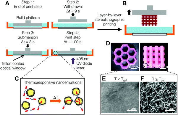
Self-assembly is a popular method to engineer hierarchical microstructure in many types of soft materials including polymeric hydrogels.1 Hydrogels can be formed through chemical or physical crosslinking methods, and are particularly attractive because they provide a hydrated environment with tunable diffusion profiles and mechanical properties.2–7 Existing strategies to prepare structured hydrogels include the use of freeze drying8,9 and sacrificial templating.10–12 These methods only provide a coarse level of control over the resultant porous microstructure. Spinodal decomposition and phase transitions in situ have recently emerged as viable methods to generate a variety of bicontinuous materials including bijels,13 demixing polymers,14 and nematic liquid crystals.15 These multiphase systems display a rich variety of microstructure due to the non-equilibrium thermodynamic instability of the constituent building blocks. Temperature responsiveness is inherent to many of these systems and represents a simple and effective tuning parameter to access microstructure in the micron length scale. Responsive colloids that form gel networks represent a particularly effective method of self-assembling such types of structure. Their characteristic domain size depends on the thermodynamics and kinetics of the highly non-equilibrium process.16,17 Large, heterogeneous voids with strands that range from hundreds of nanometers to tens of microns are commonly observed in colloidal gels.18Here, we show that when the dynamics of gelation are coupled to the time scales involved in three-dimensional (3D) printing processes, hydrogel materials with multiple length scales spanning nanometers to millimeters can be printed rapidly. 3D printing has gained popularity in recent years as an additive manufacturing platform that offers unparalleled flexibility in creating structures with arbitrary shapes and material properties.19,20 Compared to ink jetting and extrusion-based methods, stereolithographic (SLA) printing is a layer-by-layer prototyping technique that shows excellent compatibility with liquid polymeric materials. A traditional SLA 3D printer operates by photopolymerization at the surface of a resin reservoir, in which the constructed model is progressively built by moving downwards into the ink bath.21 Modern SLA 3D printers utilize an inverse setup and a layer-by-layer process to improve the printing resolution of each printed layer. First, a build platform is immersed into the resin tank containing the precursor ink. The microstructure is then photopolymerized using a 405 nm laser and actuated micromirrors, which patterns the desired motif through an optically transparent window. Finally, the platform is withdrawn and re-immersed again to print the next layer, with automated wiper actions between each print step to remove remnant debris on the optical window (Fig. 1). Oxygen inhibition of the free radical polymerization is an important parameter to monitor as it controls the overall printing speed.22 An oxygen permeable poly(dimethyl siloxane) (PDMS) layer is typically placed above the optical window to ensure a thin lubrication layer between the printed model and the resin tank, which prevents the model from adhering permanently to the window.19,23,24
In order to leverage SLA printing for the fabrication of self-assembled hydrogels, the rheological properties of the ink should be compatible with the movement of the build platform. High strain rate deformations are applied to the ink as the platform is repeatedly immersed and retracted over the duration of the printing process. Many viscoelastic self-assembled materials can exhibit fluid instabilities25 and yield irreversibly under these types of large stresses.26 Thus, in order to print 3D mesostructured hydrogels with high speed and fidelity, the ink must be able to recover its original microstructure rapidly after yielding. In addition, the material should exhibit liquid-like response27 during platform movement such that it conforms to the base of the printed motif. Here, we demonstrate that thermoresponsive nanoemulsions, which belong to a class of multiphase materials, can be printed into hierarchical structures using a modern 3D SLA printer when the rheology of the complex fluid during the printing process is accounted for.
2. Experimental section
Materials
We present a oil-in-water nanoemulsion-based ink with rheological and photoreactive properties that satisfy the requirements of SLA 3D printing. Chemicals are purchased from Sigma-Aldrich and used without further purification unless noted. The nanoemulsions consist of a continuous phase with 33 vol% poly(ethylene glycol) dimethacrylate (PEGDMA, molecular weight Mn = 750 g mol−1) and 200 mM sodium dodecyl sulfate (SDS) dissolved in deionized (DI) water, as well as an oil phase consisting of poly(dimethyl siloxane) (PDMS) droplets (viscosity, η = 5 cP) suspended at a volume fraction of ϕ = 0.25. The hydrophobic fluorescent dye Nile red (excitation wavelength = 550 nm, emission wavelength = 626 nm) is dissolved in the PDMS at a concentration of 0.05 mg mL−1 to enable confocal microscopy imaging of the nanoemulsions.To synthesize the nanoemulsions, a crude emulsion is first prepared by adding the oil phase into the continuous phase under stirring. The crude emulsions are then passed through a high pressure homogenizer (Emulsiflex-C3, AVESTIN) at a pressure of 15![[thin space (1/6-em)]](https://www.rsc.org/images/entities/char_2009.gif) 000 psi for 20 passes. A heat exchanger is used to chill the sample to 5 °C between each pass. After homogenization, the nanoemulsions are placed in a centrifuge at 5000 rpm to remove any large impurities and the supernatant is stored at 4 °C until further use. The final diameter of the droplets is measured using dynamic light scattering (90Plus PALS, Brookhaven Instruments) after dilution to ϕ = 0.002 with a solvent of 33 vol% PEGDA in DI water (η = 5.8 cP). The diameter of the nanoemulsion droplets synthesized using this homogenizing method is 2a = (40 ± 8) nm.28
000 psi for 20 passes. A heat exchanger is used to chill the sample to 5 °C between each pass. After homogenization, the nanoemulsions are placed in a centrifuge at 5000 rpm to remove any large impurities and the supernatant is stored at 4 °C until further use. The final diameter of the droplets is measured using dynamic light scattering (90Plus PALS, Brookhaven Instruments) after dilution to ϕ = 0.002 with a solvent of 33 vol% PEGDA in DI water (η = 5.8 cP). The diameter of the nanoemulsion droplets synthesized using this homogenizing method is 2a = (40 ± 8) nm.28
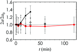
In order to synthesize the SLA printer ink, we require a photoinitiator additive that is compatible with the nanoemulsions and that is tailored to the wavelength of the laser source. The photoinitiator 2-hydroxy-2-methylpropiophenone (Darocur) is typically used in photocuring applications. However, we find that the nanoemulsion droplet size becomes unstable and increases significantly when Darocur is incorporated (Fig. 2). An alternative photoinitiator is phenylbis(2,4,6-trimethylbenzoyl) phosphine oxide (TPO), which exhibits significant absorbance in the λ = 385 to 420 nm wavelength range and high molar extinction coefficients.29 TPO is commonly used in photocurable resins because of the overlap between its absorbance spectrum and the emission wavelength of the near-UV light sources in 3D printing. We find that adding 0.1 g mL−1 of TPO in a 2 vol% co-solvent of butyl acetate provides the best balance between solubility, nanoemulsion stability and photocurability. The droplet size remains stable over a period of 2 h, which is comparable to the total print time. The photoinitiator additive is added to the nanoemulsion suspension at 2 vol% to generate fresh samples prior to each 3D printing experiment.
SLA printer modifications and setup
During the polymerization step in the chemical crosslinking of PEGDMA, the presence of oxygen slows the reaction by scavenging reactive photoinitiator radicals.22 While this is normally undesirable, having a sufficiently thick oxygen inhibition layer below the cure zone is necessary to avoid scaffold adhesion to the optical window.19,23,24 We modify the resin tank of a commercially available desktop SLA printer (Form 2, FormLabs) by replacing the PDMS layer above the optical window with a thin, optically transparent Teflon coating to ensure a sufficient lubrication layer resulting from the unpolymerized ink.19 Teflon is effective because it has one of the highest oxygen permeabilites in polymeric materials (1600 barrers = 1.2 × 10⁻¹⁴ m2 s−1 Pa−1![[thin space (1/6-em)]](https://www.rsc.org/images/entities/char_2009.gif) 30) that is double that of PDMS (800 barrers = 0.6 × 10⁻¹⁴ m2 s−1 Pa−1
30) that is double that of PDMS (800 barrers = 0.6 × 10⁻¹⁴ m2 s−1 Pa−1![[thin space (1/6-em)]](https://www.rsc.org/images/entities/char_2009.gif) 31). The procedure to modify the resin tank is as follows. After removal of the PDMS layer, the surface of the window is treated with a high frequency electrode gun (BD-10AS, Electro-Technic Products). The plasma-treated window is evenly coated with 1H,1H,2H,2H-perfluorooctyltrimethoxysilane (Matrix Scientific) and baked in an oven (T = 80 °C) for at least 8 h. The window is then cleaned with pure ethanol, dried, and coated with a layer of 1 wt% poly(4,5-difluoro-2,2-bis-trifluoromethyl-1,3-dioxole-co-tetrafluoroethylene) (Teflon AF 2400) in tetradecafluorohexane (FC-72). After the Teflon coating is completely dried, the edges of the optical window are reinforced with a UV adhesive (NOA 65, Norland Optics) to prevent nanoemulsion ink leakage into the optical chamber of the 3D printer.
31). The procedure to modify the resin tank is as follows. After removal of the PDMS layer, the surface of the window is treated with a high frequency electrode gun (BD-10AS, Electro-Technic Products). The plasma-treated window is evenly coated with 1H,1H,2H,2H-perfluorooctyltrimethoxysilane (Matrix Scientific) and baked in an oven (T = 80 °C) for at least 8 h. The window is then cleaned with pure ethanol, dried, and coated with a layer of 1 wt% poly(4,5-difluoro-2,2-bis-trifluoromethyl-1,3-dioxole-co-tetrafluoroethylene) (Teflon AF 2400) in tetradecafluorohexane (FC-72). After the Teflon coating is completely dried, the edges of the optical window are reinforced with a UV adhesive (NOA 65, Norland Optics) to prevent nanoemulsion ink leakage into the optical chamber of the 3D printer.
To print hierarchical materials using the thermoresponsive nanoemulsions, the 3D printer is placed in an environmental incubator (Model 3110, Thermo Forma) set to six different temperatures (T = 22.0 °C, 28.5 °C, 31.5 °C, 34.0 °C, 38.0 °C, 39.5 °C). The setup is allowed to equilibrate for at least 2 h prior to starting the printing experiment. Approximately 250 mL of the freshly prepared nanoemulsion ink is loaded into the resin tank and allowed to rest quiescently for 10 min to induce thermogelation. Samples used for confocal microscopy and scanning electron microscopy imaging are printed as slabs (20 mm × 80 mm × 1.5 mm) with 15 layers (thickness = 100 μm per layer). The total print time for each slab is 32 min.
Rheological characterization
Rheological measurements on the nanoemulsions are carried out using a stress-controlled rheometer (AR-G2, TA Instruments) equipped with an aluminum 2° cone-and-plate geometry (diameter = 60 mm, truncation gap = 58 μm). Small amplitude oscillatory measurements (strain γ = 5 × 10⁻⁴, angular frequency ω = 20 rad s−1) are used in the temperature ramp (ramp rate = 0.5 °C min−1) and temperature jump studies (T = 22.0 °C, 30.0 °C, 35.0 °C, 40.0 °C, 45.0 °C). The linear viscoelastic moduli, G′ and G′′, are monitored over the duration of the oscillatory measurements. In order to avoid slip, ultra fine sandpaper (320 grit) is adhered to the top geometry and the bottom Peltier plate for stress sweep experiments (γ = 1 × 10⁻⁴ to 15, ω = 20 rad s−1), repeated yielding/recovery experiments (γ = 10, ω = 20 rad s−1 and Δt = 20 s for the yield step; γ = 5 × 10⁻⁴, ω = 20 rad s−1 and Δt = 80 s for the recovery step), as well as steady shear experiments (shear stress σ = 0.01 to 100 Pa) that measure the change in nanoemulsion viscosity as a function of shear rate. We use pure nanoemulsions that has been passed through a 1.5 μm nylon filter in the rheological studies. A temperature ramp oscillatory experiment on nanoemulsions containing 2 vol% of the photoinitiator mixture is conducted to check for consistency in the gelation temperature Tgel.Sacrificial templating and bead infusion studies
The nanoemulsions are removed from the printed hydrogels using a gradual solvent transfer process. Briefly, samples are rinsed with pure ethanol, transferred into a 1![[thin space (1/6-em)]](https://www.rsc.org/images/entities/char_2009.gif) :
:![[thin space (1/6-em)]](https://www.rsc.org/images/entities/char_2009.gif) 1 v/v isopropanol/ethanol mixture for 30 min, followed by a first soak in pure toluene for 2 h. The toluene bath is replaced with fresh solvent and samples are allowed to sit for at least 12 h to ensure complete removal of the PDMS, which is verified by a loss in fluorescence. To re-hydrate the samples, a reverse solvent transfer into 1
1 v/v isopropanol/ethanol mixture for 30 min, followed by a first soak in pure toluene for 2 h. The toluene bath is replaced with fresh solvent and samples are allowed to sit for at least 12 h to ensure complete removal of the PDMS, which is verified by a loss in fluorescence. To re-hydrate the samples, a reverse solvent transfer into 1![[thin space (1/6-em)]](https://www.rsc.org/images/entities/char_2009.gif) :
:![[thin space (1/6-em)]](https://www.rsc.org/images/entities/char_2009.gif) 1 v/v isopropanol/ethanol, 1
1 v/v isopropanol/ethanol, 1![[thin space (1/6-em)]](https://www.rsc.org/images/entities/char_2009.gif) :
:![[thin space (1/6-em)]](https://www.rsc.org/images/entities/char_2009.gif) 1 v/v ethanol/DI water, and finally pure DI water is used. Samples are kept in DI water for at least 24 h to swell to their equilibrium state.
1 v/v ethanol/DI water, and finally pure DI water is used. Samples are kept in DI water for at least 24 h to swell to their equilibrium state.
Fluorescent carboxylated polystyrene beads (5 wt%, diameters = 50 nm, 200 nm, and 1.0 μm, excitation/emission wavelengths = 505/515 nm) are purchased from Invitrogen and used without further purification. We place the porous hydrogel samples in 200 μL of the bead suspension for 4 h. After rinsing with DI water, the samples are ready for confocal microscopy imaging.
Microscopy imaging
We use confocal laser scanning microscopy (CLSM) to visualize the internal structure of the printed samples containing nanoemulsions and those containing fluorescent beads after sacrificial templating. Imaging is performed on a Nikon A1R CLSM equipped with a resonant scanner head, diode lasers emitting at 488 and 561 nm, and a 60× oil immersion objective (NA = 1.4, working distance = 13 mm). Samples with dimensions of 5 mm × 5 mm × 1 mm are directly cut from the printed hydrogels and placed on a #1.5 coverslip for imaging in the xy- and xz-planes. The xy-plane images used for structural analysis have dimensions of 60.9 μm × 60.9 μm with a pixel size of 119 nm. A fast Fourier transform (FFT) is applied to the raw images using the image processing software ImageJ (NIH). The radially averaged scattered light intensity of the FFT images, I(q), is obtained using a radial profile plugin to ImageJ.Porous hydrogel samples (T = 22 °C, 34.0 °C) are also imaged with a high resolution scanning electron microscope (HRSEM, Zeiss) at 5 kV accelerating voltage. Samples are cut into thin (∼1 mm) sections, dried for at least 48 h at room temperature, and then adhered with carbon tape onto SEM stubs. All samples are sputter coated with approximately 10 nm of a Au–Pd alloy prior to imaging.
Mechanical characterization of filled and porous hydrogels
Nanoemulsion inks are photopolymerized into a traditional dogbone shape (cross sectional area, A0 = 1.00 × 10⁻⁵ m2, testing area length, L0 = 15 mm, thickness = 2 mm) for stress–strain mechanical testing. Briefly, 800 μL of nanoemulsions is added into a dogbone-shaped mold made out of a transparent polycarbonate sheet. A microscope coverslip is used to cover the top of the mold. The filled mold is placed in a vacuum oven (heated to the various temperatures used in the 3D printing) purged with nitrogen gas in order to remove oxygen from the samples. This permits even curing during the photopolymerization and reduces the formation of air bubbles. After an hour, the mold is placed under a UV lamp for 5 minutes to fully photopolymerize the hydrogels. To generate porous hydrogels for mechanical testing, we further treat the dogbones with toluene and rehydrate using the procedure that is described in the experimental section under sacrificial templating.Both ends of the hydrogel dogbones are attached to cardboard scaffold using UV glue (NOA 65, Norland Optics). The cardboard pieces are clamped directly onto a set of 10N load cells on an Instron 8840 MicroTester. The testing procedure involves the application of an uniaxial extensional strain at a rate of 0.01 mm s−1 until rupture occurs. Young's modulus is obtained using the relation, E = σe/ε = (FL0)/(A0ΔL), where σe is the tensile stress, ε is the applied strain, F is the applied load, L0 and A0 are the original dimensions of the hydrogel dogbone, and ΔL is the deformation length measured by the Instron tester. The engineering rupture stress is obtained using the relation σrup = Frup/A0 where Frup is the measured force at which the sample fractures. A minimum of six independently prepared samples are used to generate each data point.
3. Results and discussion
Printing of self-assembled nanoemulsion hydrogels
The schematic in Fig. 1A and B shows the dynamical process used to print nanoemulsion-filled hydrogels with macroscopic features (honeycomb and multi-tier woodpile hydrogels are shown in Fig. 1D). Using temperature as a tuning parameter, we are able to print hydrogels that have internal microstructure that range from nanometer-sized droplets to mesoscopic structures. At T < Tgel, the nanoemulsions are photo-crosslinked into a homogeneous matrix. When the temperature is raised beyond a critical gelation point Tgel, the hydrophobic end groups on the PEGDMA molecules partition into the oil phase and serve as interdroplet bridges32 (Fig. 1C), leading to the formation of a viscoelastic colloidal gel with different microstructures (Fig. 1E and F). Depending on application needs, these domains can either serve as pathways for the transport of hydrophobic molecules or be extracted to leave behind interconnected pores.Rheological properties of the nanoemulsion inks
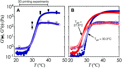
The viscoelasticity of the gelled nanoemulsions is an inherent material property that is directly correlated with the stress-bearing microstructure and dynamics of the gel network.33,34 As such, the internal length scale of the printed hydrogel scaffold can be estimated a priori by measuring the elastic (G′) and viscous moduli (G′′) of the nanoemulsions as a function of temperature using small amplitude oscillatory rheology.The temperature ramp experiments shown in Fig. 2 are performed at a heating rate of 0.5 °C min−1 to generate high resolution viscoelastic data at small temperature intervals. As temperature increases, G′ and G′′ increase rapidly and reach a plateau at high temperatures. The point at which G′ = G′′ sets the value of Tgel = 29.2 °C for this particular nanoemulsion system, although the gel temperature can be easily adjusted by replacing PEGDMA with other crosslinking molecules with two or more hydrophobic end groups.32 To account for the effect of the heating rate, we perform temperature jump measurements that are representative of print conditions. Fig. 3A indicates that G′ and G′′ follow the same trend as the temperature ramp experiments, and that Tgel is found within a similar range. The rheology data shown in Fig. 3A and 4B–D are generated using pure nanoemulsions. Addition of the photoinitiator additive results in a minor reduction in Tgel to 27.6 °C (Fig. 3B), although the overall rheological behavior remains similar.
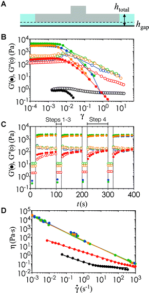
In order to characterize the rheology of the nanoemulsion inks during the printing process, we estimate the compressive strain, γ, as the relative vertical displacement of the fluid induced by the platform movement, and the strain rate, ![[small gamma, Greek, dot above]](https://www.rsc.org/images/entities/i_char_e0a2.gif) , using the linear velocity of the motorized stage through the ink (Fig. 4A). The motorized platform moves at an average speed of 1.27 cm s−1 in the withdrawal and re-submersion steps (steps 2 and 3 in Fig. 1A). There is a constant gap of hgap = 100 μm, set by the z-resolution of the printer, between the optical window and the bottom of the printed model. The total height of the fluid stays relatively constant at htotal ∼ 7.5 mm. Yielding of the gels occurs at strain units (γ < 0.01) lower than the deformation imposed during the print process by the build platform in the printer (γ ∼ 0.98).
, using the linear velocity of the motorized stage through the ink (Fig. 4A). The motorized platform moves at an average speed of 1.27 cm s−1 in the withdrawal and re-submersion steps (steps 2 and 3 in Fig. 1A). There is a constant gap of hgap = 100 μm, set by the z-resolution of the printer, between the optical window and the bottom of the printed model. The total height of the fluid stays relatively constant at htotal ∼ 7.5 mm. Yielding of the gels occurs at strain units (γ < 0.01) lower than the deformation imposed during the print process by the build platform in the printer (γ ∼ 0.98).
Fig. 4B shows that there is a transition from the linear Glin′ at low γ to the nonlinear regime beyond the yield strain γy, where G′ decreases by more than three orders of magnitude. We note here that the angular frequency (ω) of the oscillatory rheology is set to 20 rad s−1 to generate high resolution data on the rheometer. This value of ω provides the correct values G′ and G′′ particularly when they become insensitive to differences in ω above the gel point of a viscoelastic suspension.35 We use repeated cycles of large amplitude oscillatory shear (LAOS) and small amplitude oscillatory shear (SAOS) to investigate the structural recovery of the inks under the deformation imposed during the printing process. In the LAOS cycle, a strain amplitude much larger than the yield strain of the nanoemulsion is applied to simulate the withdrawal and submersion steps of printing. In the SAOS cycle, a small strain is used to probe the viscoelastic recovery of the ink during the print step. The timescales and parameters of the LAOS and SAOS cycle are matched to the printing step timescales as shown in Fig. 1A. Fig. 4C shows that the gelled nanoemulsions recovers to its original state rapidly and reversibly once the deformation ceases. This structural recovery is key to printing hydrogels with continuous and well-controlled internal microstructure in all three dimensions.
Within the operation range of the moving build platform (![[small gamma, Greek, dot above]](https://www.rsc.org/images/entities/i_char_e0a2.gif) = 1.7 s−1), the nanoemulsions undergo shear thinning with a viscosity upper range of ∼100 Pa
= 1.7 s−1), the nanoemulsions undergo shear thinning with a viscosity upper range of ∼100 Pa![[thin space (1/6-em)]](https://www.rsc.org/images/entities/char_2009.gif) s (Fig. 4D). The yield stress, σy, and the power law exponent, n, can be obtained from fitting the Herschel–Bulkley model σ = σy + k
s (Fig. 4D). The yield stress, σy, and the power law exponent, n, can be obtained from fitting the Herschel–Bulkley model σ = σy + k![[small gamma, Greek, dot above]](https://www.rsc.org/images/entities/i_char_e0a2.gif) n to the viscosity data, where k is a consistency parameter and the steady shear viscosity is η = σ/
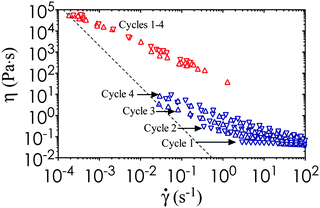
n to the viscosity data, where k is a consistency parameter and the steady shear viscosity is η = σ/![[small gamma, Greek, dot above]](https://www.rsc.org/images/entities/i_char_e0a2.gif) .36 A purely Newtonian liquid has constant viscosity at all shear rates (n = 1), whereas 0 ≤ n < 1 for a shear thinning fluid. These material properties are shown in Table 1 for nanoemulsions at different temperatures. In addition, we perform steady state characterization of the thermoresponsive nanoemulsions at T = 22 °C and 40 °C, which encompasses the full range of conditions tested in our study. We observe some viscosity hysteresis of the nanoemulsions at T = 22 °C, but none at T = 40 °C (Fig. 5). This gradual increase in viscosity over multiple cycles at low temperatures could be explained by the formation of flow-induced clusters from the Brownian relaxation of the nanoemulsions and structural relaxation of the PEGDMA matrix with respect to viscous forces.37 Nevertheless, the printed microstructure is unlikely to be affected by the shear imposed by the build platform given the long equilibration time during the print step. The yield stress of the material does present issues if the print area is not properly refilled after the withdrawal of the build platform. Classical Saffman–Taylor instabilities can also lead to viscous fingering that are comparable to the length scale of the self-assembled gel network within the nanoemulsions.38 Thus, wiper operations are necessary to spread the ink out evenly between each layer-by-layer cycle in the printing process.
.36 A purely Newtonian liquid has constant viscosity at all shear rates (n = 1), whereas 0 ≤ n < 1 for a shear thinning fluid. These material properties are shown in Table 1 for nanoemulsions at different temperatures. In addition, we perform steady state characterization of the thermoresponsive nanoemulsions at T = 22 °C and 40 °C, which encompasses the full range of conditions tested in our study. We observe some viscosity hysteresis of the nanoemulsions at T = 22 °C, but none at T = 40 °C (Fig. 5). This gradual increase in viscosity over multiple cycles at low temperatures could be explained by the formation of flow-induced clusters from the Brownian relaxation of the nanoemulsions and structural relaxation of the PEGDMA matrix with respect to viscous forces.37 Nevertheless, the printed microstructure is unlikely to be affected by the shear imposed by the build platform given the long equilibration time during the print step. The yield stress of the material does present issues if the print area is not properly refilled after the withdrawal of the build platform. Classical Saffman–Taylor instabilities can also lead to viscous fingering that are comparable to the length scale of the self-assembled gel network within the nanoemulsions.38 Thus, wiper operations are necessary to spread the ink out evenly between each layer-by-layer cycle in the printing process.
| T (°C) | σ y (Pa) | n | G lin′ (Pa) |
|---|---|---|---|
| 22.0 | 0.06 | 0.75 | 0.17 |
| 30.0 | 0.08 | 0.41 | 3.24 |
| 35.0 | 22 | 0.25 | 899.4 |
| 40.0 | 25 | 0.30 | 2224 |
| 45.0 | 28 | 0.28 | 2210 |
Hydrogel microstructure and mechanical properties
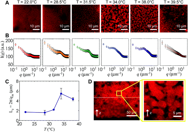
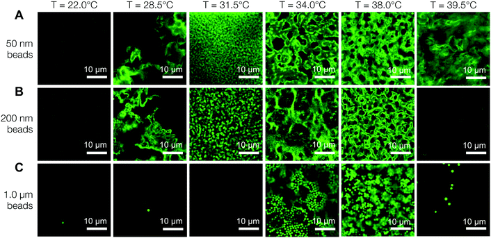
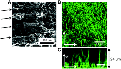
Fig. 6A is a panel of representative confocal laser scanning microscopy (CLSM) images in the xy-plane that show the range of microstructures of the hydrogels printed with the self-assembling nanoemulsions. Visual inspection shows that the scaffold is mostly homogeneous below the gel temperature at T = 22.0 °C. Finely percolated networks form near the gel point at T = 28.5 °C, which develop into spinodal-like structures at T = 34.0 °C. As the temperature is further increased to T = 39.5 °C, arrested phase separation results in a decrease in the length scale of the colloid-rich regions. We compute the scattered intensity I(q) from a fast Fourier transform (FFT) applied to the raw 2D images (Fig. 6B), where q represents the wave vector or inverse length in real space. The characteristic gel length scale, Lc = 2π/qm, is defined by the local peak qm in the I(q) plots where possible and is plotted in Fig. 6C. The value of Lc increases gradually to a maximum at T = 34.0 °C, followed by a decrease that is brought on by kinetic arrest at higher temperatures.16 These results are in agreement with our earlier work on a similar system of thermoresponsive nanoemulsions in which samples were cast into molds.39 In addition, we verify that the connective mesoscale structure is preserved between each printed layer. A zoomed out CLSM image of the hydrogel scaffold in the direction perpendicular to the printing (xz-plane) is shown in Fig. 6D, where a dashed line indicates the boundary of the two layers as observed in HRSEM images in Fig. 8A.The interconnectivity of the gel networks formed by the self-assembled thermoresponsive nanoemulsions allows for the transport of molecules and mesoscopic objects. We demonstrate this capability by using the nanoemulsions as a sacrificial template that is extracted from the 3D printed hydrogels through solvent transfer with pure toluene. After rehydration, we immerse the samples in aqueous solutions containing fluorescent, carboxylated polystyrene beads with diameters of 50 nm, 200 nm, and 1.0 μm. Fig. 7 illustrates the capability of the printed porous hydrogels to serve as size-selective membranes. Beads of all sizes are able to diffuse into hydrogels having comparatively larger pore size (T = 34.0 °C and 38.0 °C) but not those with smaller pores (T = 28.5 °C, 31.5 °C, 39.5 °C). The control scaffold sample printed at T = 22.0 °C (T < Tgel) does not permit the passage of the smallest bead size (50 nm) because of the isolated pore structure within it. A representative 3D CLSM image of a porous sample printed at T = 34.0 °C and treated with 200 nm beads shows that the fluorescent beads are able to diffuse into the channels in x, y, and z-directions (Fig. 8B). The xz-image of a porous sample (T = 34.0 °C) in Fig. 8C is captured from an xyz-stack; here, the imaging height is limited to 24 μm due to significant scattering from the remainder of the sample.
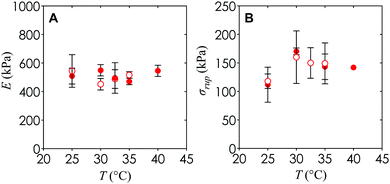
An additional observation is that the Young's modulus and engineering rupture stress for hydrogels with and without nanoemulsions remain similar to within the experimental uncertainty (Fig. 9). This suggests that the mechanical properties of the hydrogel can be tuned completely independently from the internal architecture necessary for diffusion of nutrients or cell passage, which could be important in future applications of this material towards synthetic microvasculature and 3D cellular scaffolds.
4. Conclusions
Thermoresponsive nanoemulsions belong to a class of stimuli-responsive materials that are compatible with 3D SLA printing to generate hierarchical materials with tunable mesoscale structures. The PEGDMA molecules in the nanoemulsion ink serve two important functions: (1) they induce colloidal gelation in which the characteristic length scale can be tuned based on the temperature, and (2) they provide photochemically crosslinked hydrogel materials on demand. Using a commercially available 3D printer with modifications to the resin tray to enhance oxygen permeability, we demonstrate that these nanoemulsions can serve as self-assembling precursor inks to be rapidly photopolymerized into macroscale shapes with the desired internal features. Correct selection of the photoinitiator is critical to maintain the stability of the nanoemulsions over the course of the printing process and to provide photoreactive response with the near-UV (λ = 405 nm) light sources that are commonly used in commercial 3D SLA printers. In addition, the rapid structural recovery and shear thinning rheological properties of the ink is necessary for generating hierarchical materials with an interconnected morphology that allows the mass transport of mesoscopic objects into the hydrogels. However, due to the yield stress behavior of these inks, wiper operations between successive print steps are needed to spread the ink out evenly.Future possibilities for these mesoporous materials include the crystallization of hydrophobic molecules in nanoemulsion-carrying channels for controlled or triggered drug delivery,40 synthetic vasculature,41 or in understanding the deformation mechanics of tissue-like models that can be printed in multiple shapes and sizes.42 Other applications involve retaining the nanoemulsions in the printed structure to serve as reservoirs for hydrophobic drugs,43 modulating the mass transfer of gases,44 or acting as sinks for metals/organics in water treatment processes.45
Competing financial interest
The authors declare no competing financial interest.Acknowledgements
This work was supported primarily by the MRSEC Program of the National Science Foundation under DMR – 1419807. The authors thank Prof. G. McKinley for the use of the rheometer and J. F. Hamel for loan of the environmental incubator.References
- S. C. Glotzer and M. J. Solomon, Nat. Mater., 2007, 6, 557 CrossRef PubMed.
- J. Malda, J. Visser, F. P. Melchels, T. Jüngst, W. E. Hennink, W. J. Dhert, J. Groll and D. W. Hutmacher, Adv. Mater., 2013, 25, 5011 CrossRef CAS PubMed.
- C.-C. Lin and K. S. Anseth, Pharm. Res., 2009, 26, 631 CrossRef CAS PubMed.
- B. V. Slaughter, S. S. Khurshid, O. Z. Fisher, A. Khademhosseini and N. A. Peppas, Adv. Mater., 2009, 21, 3307 CrossRef CAS PubMed.
- L. Hockaday, et al. , Biofabrication, 2012, 4, 035005 CrossRef CAS PubMed.
- A. Khademhosseini and R. Langer, Biomaterials, 2007, 28, 5087 CrossRef CAS PubMed.
- M. P. Cuchiara, D. J. Gould, M. K. McHale, M. E. Dickinson and J. L. West, Adv. Funct. Mater., 2012, 22, 4511 CrossRef CAS PubMed.
- P. B. Welzel, J. Friedrichs, M. Grimmer, S. Vogler, U. Freudenberg and C. Werner, Adv. Healthcare Mater., 2014, 3, 1849 CrossRef CAS PubMed.
- L.-W. Xia, R. Xie, X.-J. Ju, W. Wang, Q. Chen and L.-Y. Chu, Nat. Commun., 2013, 4, 2226 Search PubMed.
- A. N. Stachowiak, A. Bershteyn, E. Tzatzalos and D. J. Irvine, Adv. Mater., 2005, 17, 399 CrossRef CAS.
- Y. J. Lee and P. V. Braun, Adv. Mater., 2003, 15, 563 CrossRef CAS.
- P. X. Ma and J.-W. Choi, Tissue Eng., 2001, 7, 23 CrossRef CAS PubMed.
- M. N. Lee and A. Mohraz, Adv. Mater., 2010, 22, 4836 CrossRef CAS PubMed.
- Y. S. Nam and T. G. Park, J. Biomed. Mater. Res., 1999, 47, 8 CrossRef CAS PubMed.
- H. Diestra-Cruz, E. Bukusoglu, N. L. Abbott and A. Acevedo, ACS Appl. Mater. Interfaces, 2015, 7, 7153 CAS.
- J. Conrad, H. Wyss, V. Trappe, S. Manley, K. Miyazaki, L. Kaufman, A. Schofield, D. Reichman and D. Weitz, J. Rheol., 2010, 54, 421 CrossRef CAS.
- V. J. Anderson and H. N. Lekkerkerker, Nature, 2002, 416, 811 CrossRef CAS PubMed.
- P. J. Lu, E. Zaccarelli, F. Ciulla, A. B. Schofield, F. Sciortino and D. A. Weitz, Nature, 2008, 453, 499 CrossRef CAS PubMed.
- J. R. Tumbleston, et al. , Science, 2015, 347, 1349 CrossRef CAS PubMed.
- A. S. Gladman, E. A. Matsumoto, R. G. Nuzzo, L. Mahadevan and J. A. Lewis, Nat. Mater., 2016, 15, 413 CrossRef PubMed.
- M. N. Cooke, J. P. Fisher, D. Dean, C. Rimnac and A. G. Mikos, J. Biomed. Mater. Res., Part B, 2003, 64, 65 CrossRef PubMed.
- S. C. Ligon, B. Husár, H. Wutzel, R. Holman and R. Liska, Chem. Rev., 2013, 114, 557 CrossRef PubMed.
- D. Dendukuri, P. Panda, R. Haghgooie, J. M. Kim, T. A. Hatton and P. S. Doyle, Macromolecules, 2008, 41, 8547 CrossRef CAS.
- D. Dendukuri, D. C. Pregibon, J. Collins, T. A. Hatton and P. S. Doyle, Nat. Mater., 2006, 5, 365 CrossRef CAS PubMed.
- K. J. LeBlanc, S. R. Niemi, A. I. Bennett, K. L. Harris, K. D. Schulze, W. G. Sawyer, C. Taylor and T. E. Angelini, ACS Biomater. Sci. Eng., 2016, 2, 1796 CrossRef CAS.
- R. G. Larson, The Structure and Rheology of Complex Fluids, Oxford University Press, New York, NY, 1999 Search PubMed.
- B. G. Compton and J. A. Lewis, Adv. Mater., 2014, 26, 5930 CrossRef CAS PubMed.
- A. Gupta, H. B. Eral, T. A. Hatton and P. S. Doyle, Soft Matter, 2016, 12, 1452 RSC.
- A. A. Pawar, G. Saada, I. Cooperstein, L. Larush, J. A. Jackman, S. R. Tabaei, N.-J. Cho and S. Magdassi, Sci. Adv., 2016, 2, e1501381 Search PubMed.
- I. Pinnau and L. G. Toy, J. Membr. Sci., 1996, 109, 125 CrossRef CAS.
- T. Merkel, V. Bondar, K. Nagai, B. Freeman and I. Pinnau, J. Polym. Sci., Part B: Polym. Phys., 2000, 38, 415 CrossRef CAS.
- M. E. Helgeson, S. E. Moran, H. Z. An and P. S. Doyle, Nat. Mater., 2012, 11, 344 CrossRef CAS PubMed.
- L. C. Hsiao, R. S. Newman, S. C. Glotzer and M. J. Solomon, Proc. Natl. Acad. Sci. U. S. A., 2012, 109, 16029 CrossRef CAS PubMed.
- L. C. Hsiao, H. Kang, K. H. Ahn and M. J. Solomon, Soft Matter, 2014, 10, 9254 RSC.
- H. H. Winter and F. Chambon, J. Rheol., 1986, 30, 367 CrossRef CAS.
- H. Zhu, Y. Kim and D. De Kee, J. Non-Newtonian Fluid Mech., 2005, 129, 177 CrossRef CAS.
- J. Kim and M. E. Helgeson, Phys. Rev. Fluids, 2016, 1, 043302 CrossRef.
- J. Nase, A. Lindner and C. Creton, Phys. Rev. Lett., 2008, 101, 074503 CrossRef PubMed.
- L. C. Hsiao and P. S. Doyle, Soft Matter, 2015, 11, 8426 RSC.
- A. Z. M. Badruddoza, P. D. Godfrin, A. S. Myerson, B. L. Trout and P. S. Doyle, Adv. Healthcare Mater., 2016, 5, 1960 CrossRef CAS PubMed.
- N. Doshi, B. Prabhakarpandian, A. Rea-Ramsey, K. Pant, S. Sundaram and S. Mitragotri, J. Controlled Release, 2010, 146, 196 CrossRef CAS PubMed.
- T. W. Sirk, K. S. Khare, M. Karim, J. L. Lenhart, J. W. Andzelm, G. B. McKenna and R. Khare, Polymer, 2013, 54, 7048 CrossRef CAS.
- H. Z. An, M. E. Helgeson and P. S. Doyle, Adv. Mater., 2012, 24, 3838 CrossRef CAS PubMed.
- H. Z. An, E. R. Safai, H. B. Eral and P. S. Doyle, Lab Chip, 2013, 13, 4765 RSC.
- A. Sayari, S. Hamoudi and Y. Yang, Chem. Mater., 2005, 17, 212 CrossRef CAS.
Footnote |
| † Present address: Department of Chemical and Biomolecular Engineering, North Carolina State University, Raleigh, NC 27695, USA. |
| This journal is © The Royal Society of Chemistry 2017 |

