
 Open Access Article
 This Open Access Article is licensed under a
 Creative Commons Attribution 3.0 Unported Licence
Harnessing the advantages of hard and soft colloids by the use of core–shell particles as interfacial stabilizers
C.
Buchcic
 *ab,
R. H.
Tromp
ac,
M. B. J.
Meinders
ad and
M. A.
Cohen Stuart
b
*ab,
R. H.
Tromp
ac,
M. B. J.
Meinders
ad and
M. A.
Cohen Stuart
b
aTop Institute Food and Nutrition, Wageningen, The Netherlands. E-mail: christian.buchcic@gmail.com
bPhysical Chemistry and Soft Matter, Wageningen, The Netherlands
cNizo Food Research, Ede, The Netherlands
dWageningen UR, Food and Biobased Research, Wageningen, The Netherlands
First published on 11th January 2017
Abstract
The ability of colloidal particles to penetrate fluid interfaces is a crucial factor in the preparation of particle stabilized disperse systems such as foams and emulsions. For hard micron-sized particles the insertion into fluid interfaces requires substantial energy input, but soft particles are known to adsorb spontaneously. Particle hardness, however, may also affect foam and emulsion stability. The high compliance of soft particles may compromise their ability to withstand the lateral compression associated with disproportionation. Hence, particles which can spontaneously adsorb onto fluid interfaces, and yet depict low compliance may be ideal as interfacial stabilizers. In the present work, we prepared core–shell particles comprising a hard, polystyrene core and a soft poly(N-isopropylacrylamide) based shell. We found that such core–shell particles adsorb spontaneously onto various fluid interfaces. The absence of a pronounced energy barrier for interfacial adsorption allowed the facile preparation of particle-stabilized bubbles as well as emulsion droplets. For bubbles, the stability was better than that of bubbles stabilized by entirely soft particles, but disproportionation was not stopped completely. Emulsion droplets, in contrast, showed excellent stability against both coalescence and disproportionation. Lateral compression of core–shell particles due to disproportionation was clearly limited by the presence of the polystyrene core, leading to long-lasting stability. For emulsions, we even observed non-spherical droplets, indicating a negligible Laplace pressure. Our results indicate that core–shell particles comprising a hard core and a soft shell combine the advantageous properties of hard and soft particles, namely spontaneous adsorption and limited compliance, and can therefore be superior materials for the preparation of particle-stabilized dispersions.
Introduction
Colloidal particles are prominent alternatives to the application of small molecular weight surfactants (SMWSs) and proteins for the stabilization of disperse systems such as foams and emulsions. As these particles are typically much larger than SMWSs and proteins, they strongly anchor to the fluid interface and can impart greater stability compared to other interfacial stabilizers. Their superior stabilizing properties and ability to respond to external stimuli lead to a recent surge of research carried out in the area of particle stabilized interfaces.1–9 Particles which are used to stabilize dispersions can be differentiated into two classes by their softness and deformability: ‘soft’ particles have elastic moduli in the kPa range and can be substantially deformed by interfacial forces,9,10 while ‘hard’ particles have high elastic moduli in the GPa range and, thus, do not easily deform by interfacial forces.11Since the early work of Ramsden and Pickering, hard particles, e.g. colloidal hydrophobized silica, are known as effective stabilizers of emulsions.12 Accordingly, the term Pickering emulsion or Pickering stabilization is nowadays commonly adopted if one refers to a dispersion stabilized by solid particles. The particle's adsorption strength to fluid interfaces is largely determined by the ability of both fluids to wet the particle surface. The degree of wetting is characterized by the particle contact angle θ, with θ close to 0 degrees for hydrophilic, θ close to 180 degrees for hydrophobic and θ close to 90 degrees for particles which are equally wetted by both phases (intermediate wetting). Once particles larger than about a few nanometres with a contact angle close to 90° reside in the interfaces, they are practically irreversibly attached. This is because the energy of desorption for removing one particle from the interface into one of the two continuous phases is orders of magnitude larger than the thermal energy kBT.2
The stability of a dispersion stabilized by hard particles arises due to a steric mechanism. Once the interface of a dispersion is covered by a sufficient amount of hard particles, coalescence of individual droplets or bubbles stops. Also, Ostwald ripening, the pressure-driven exchange of materials between differently sized domains of the dispersed phase, may initially proceed but will eventually stop once interfacial particles start to experience sufficiently large lateral repulsion due to increased surface coverage. At this point a so-called ‘colloidal armour’ is formed. Ostwald ripening is arrested because the relatively high elastic modulus of hard particles inhibits their deformation and particles of appropriate wettability possess a very high adsorption energy and, thus, are unlikely to desorb from the interface due to lateral repulsion.13
An important property which qualitatively distinguishes hard particles from soft particles is their adsorption behaviour onto liquid interfaces. Hard particles, in particular when negatively charged, do not adsorb without mechanical energy input. The reasons for the difficulty in adsorbing are not always clear, but generally electrostatic effects between particles and interfaces are held to be responsible.1 The electrostatic repulsion between negatively charged hard particles and a negatively charged fluid interface causes an energy barrier for particle adsorption onto the interface.14 Promoting particle adsorption thus requires high energy input processing methods such as turbulent mixing or sonication.15 In the context of applications, it is not always possible to modify the sign of the particle charge or use high energy processing methods. Therefore, an alternative should be welcome.
In contrast to the use of hard particles, the interest in soft particles (also known as microgel particles) as dispersion stabilizers arose more recently. Microgels are colloidal particles consisting of a cross-linked polymer network which is highly swollen by a good solvent. Such particles can be routinely made by the same methods as used for the preparation of hard particles, using cross-linkers and polymers that are insoluble due to the increased temperature during the polymerization reaction, but dissolve upon subsequent cooling. Poly(N-isopropylacrylamide) (PNIPAM) is a well-known material for soft, aqueous microgels. The polymer undergoes a structural transition from coil-to-globule upon increasing the temperature above the lower critical solution temperature (LCST) which leads to a volume reduction of the microgel particles. Incorporation of ionic co-monomers into the microgels can also impart responsiveness to ionic strength and pH. These structural changes in response to external stimuli make microgels very interesting materials for the particle stabilization of fluid interfaces, as the stability of the particles comprising dispersion can be altered by changing the physico-chemical factors of the bulk solution.16
Soft particles such as PNIPAM-based microgels are compliant and can be considerably deformed by capillary forces. Soft particles typically spread out radially at the interface. This spreading stops once the energy gain from covering the interface with the polymer is balanced by the energy required for elastic deformation of the cross-linked polymer particles. Aside from the particle deformation due to interfacial spreading, aqueous microgels are usually weakly hydrated in the non-polar phase which causes the particles to be substantially flattened at the non-polar side of the interface.17
Soft particles are considered as good interfacial stabilizers for emulsion droplets.17,18 Due to their large size they irreversibly adsorb to liquid interfaces and provide a steric hindrance to coalescence.19 In addition to the steric effect, the spreading of microgels onto a liquid interface can lead to the formation of a viscoelastic interfacial layer which can provide certain kinetic stability against Ostwald ripening.20 Very soft microgels which are highly swollen are most susceptible to form entangled contact zones leading to such a viscoelastic interface.21 On the other hand the high compliance of microgels can also be a disadvantage for their ability to provide long-term stability against Ostwald ripening. Due to their high compliance, interfacial microgels may undergo radial compression and substantially deform during Oswald ripening. This viscous deformation might impair their ability to completely stop Ostwald ripening in the same way as hard particles do.
For soft particles, interfacial adsorption occurs spontaneously and is, at least at low surface coverage, mainly governed by particle diffusion to the fluid–fluid interface.22,23 The absence of considerable energy barriers against interfacial adsorption of soft particles is desirable for the preparation of a particle stabilized dispersion, as the energy input for processing is lower and the rate of particle adsorption can be simply controlled by the process parameter concentration.
From this introduction it should become clear that both kinds of particles markedly differ in their functional properties with regard to dispersion stabilization. Spontaneous adsorption as observed for soft particles is desirable, yet, the particles' high compliance might impair the ability to establish a stress bearing network and stop Ostwald ripening. Hard particles, in contrast, can be barely deformed and can effectively stop Oswald ripening, but are difficult to bring to the interface. We want to investigate, if core–shell particles, comprising a soft shell on top of a hard core, may have the characteristics of both particle types. The soft shell may enable spontaneous adsorption onto fluid interfaces, and the hard core may provide a well-defined end-point to the lateral compression of the particle-covered interface during disproportionation.
In order to test this hypothesis, we designed core–shell particles with a solid core and a soft shell. We investigated how particles with different shell dimensions are taken up at liquid–gas and liquid–liquid interfaces, and what surface pressures they generate. We also studied the structure of particle covered interfaces, and the stability of bubbles and emulsion droplets stabilized by core–shell particles.
Materials and methods
Materials
Styrene, itaconic acid (IA), initiator 4,4′-azobis(4-cyanovaleric acid) (ACVA), N-isopropylacrylamide (NIPAM), N,N′-methylbisacrylamide (BIS), methacrylic acid (MA), potassium peroxodisulfate (KPS), divinylbenzene (DVB) and sodium chloride (NaCl) were purchased from Sigma-Aldrich. Deionized (DI) water with a resistance of 18.2 MΩ cm was used for all measurements.Synthesis of core particles
Polystyrene core particles were prepared by surfactant free emulsion polymerization. 20 g of styrene, 0.5 g of itaconic acid and 180 g of DI water were charged to a round-bottom flask sealed by a rubber septum. For cross-linked particles also 0.39 g of DVB was added. The flask was placed in an oil bath and heated to 80 °C under sparging with nitrogen gas for the duration of 20 minutes. 220 mg of the initiator 4,4′-azobis(4-cyanovaleric acid) dissolved in 5 ml of 0.2 M sodium hydroxide solution was added to the reaction mixture. The reaction proceeded for the duration of 18 hours at 80 °C under stirring at 200 rpm. After filtering through glass wool, the resulting particle dispersion was centrifuged at 2500g for 3 h. The supernatant was removed and the precipitate was re-dispersed in DI water. This centrifugation–redispersion cycle was repeated until the surface tension of the supernatant measured by tensiometry was 72 mN m−1.Synthesis of core–shell particles
Core–shell particles were prepared by precipitation polymerization using a procedure inspired from the literature.24 90 g of DI water, 0.5 g of NIPAM, 20 mg of BIS, 50 μl of MA and varying amounts of core particle dispersion were charged to a round-bottom flask sealed by a rubber septum. The flask was placed in an oil bath and heated to 80 °C under sparging with nitrogen gas for the duration of 20 minutes. 50 mg of the initiator potassium persulfate dissolved in 5 ml of DI water was added to the reaction mixture. The reaction proceeded for the duration of 2 hours at 80 °C under stirring at 200 rpm. At the end of the reaction, the resulting product was filtered through glass wool and the resulting particle dispersion was centrifuged at 2500g and a temperature of 20 °C for 2 h. The supernatant was removed and the precipitate was re-dispersed in DI water. Subsequent centrifugation steps were carried out at 5 °C and 2500g for 16 hours. These centrifugation–redispersion cycles were typically repeated three times until the surface tension of the supernatant measured by tensiometry was 72 mN m−1.Dynamic light scattering
Dynamic light scattering (DLS) was performed on an instrument from ALV (Langen, Germany) equipped with a diode-pumped solid-state laser (Cobolt Samba 300 mW at 532 nm), an ALV 50/100/200/400/600 μm pinhole system, a Thorn RFIB263KF photomultiplier detector, an ALV7002 external correlator and an ALV-SP/86 goniometer. The scattering intensity of a diluted particle dispersion was measured at a scattering angle of 90°. The temperature was kept constant at 20 °C. Diffusion coefficient D was obtained from a cumulant fit, using the second order cumulant; PDI is defined as the coefficient of the quadratic term divided by D2q4/2, where q is the scattering vector. Diffusion radii were calculated according to the Stokes–Einstein relation.Viscometry
An Ubbelohde capillary viscometer was immersed in a thermostat controlled water bath. After filling the capillary viscometer with a dispersion of core–shell particles, the relative viscosity was measured. This was done for a dilution series of various core–shell particle concentrations. These data are then fitted to the Einstein–Batchelor relation to determine the particle volume fraction. In combination with the hydrodynamic diameter from DLS, the particle volume number density c∞ was obtained.Tensiometry
The surface tension of the particle dispersion was determined on a Drop Tensiometer, model TRACKER (Teclis, France). All measurements were performed in the pendant drop configuration. Prior to the measurements, the dispersion was diluted to the desired particle concentration and adjusted to pH 6. The temperature was kept constant at 20 °C.Light microscopy
Light microscopy was done on an upright Olympus BX 50 light microscope equipped with several long working distance objectives and a reflected light, vertical illuminator. For visualization of bulk aqueous dispersions, samples were filled into a home-made glass capillary of approximately 100 μm height. For visualisation of specimens located at a fluid interface, particle dispersion and the corresponding fluids were filled in a shallow quartz cuvette (3 cm × 2 cm × 0.5 cm).Cryo-scanning electron microscopy
A stock of concentrated particle dispersion was diluted, yielding a volume number density c∞ (number of particles in a certain volume) of 9.25 × 10⁻¹⁵ m−3 with 20 mM NaCl as a background electrolyte. 40 μl of this particle dispersion was transferred to a circular copper sample holder with an inner diameter of 5 mm and a deep cavity of 1 mm. The particle dispersion was left to equilibrate for 20 minutes to enable particles to adsorb to the fluid interface. Freezing of the samples was done by plunging them in liquid nitrogen for two minutes. Subsequently, the specimens were partially freeze-dried at −93 °C for 1 min to remove ice crystals, followed by tungsten coating on a high vacuum coating system Leica EM MED 020. A uniform coating of 5 nm thickness was applied, followed by a second coating step up to a total thickness of 10 nm in which the coating was applied under an angle of 45 °C with respect to the sample surface. Sample transfer was done using a Leica EM VCT 100 vacuum cryo-transfer system. Cryo-SEM imaging was performed on an ultra-high resolution field emission scanning electron microscope FEI Magellan 400. To ensure that only the top surface of the sample, on the order of nanometres, is imaged, we opted for a low accelerating voltage of the electron beam (2 kV). The low accelerating voltage also avoids charging of the samples and detection of secondary electrons; altogether it ensures a good image quality.Results and discussion
An overview of the synthesised particles together with their sizes is given in Table 1. Please note that the particle size is a function of temperature T, salt concentration cs, and pH. Particle sizes given in Table 1 are measured at 20 °C, pH 6 and in the presence of 20 mM NaCl as a background electrolyte. The core sizes are all between 350 and 400 nm. The main source of the variation in the particle size is the variation in the shell thickness. The given shell thickness is obtained as the difference between the hydrodynamic (diffusion) radius of the core–shell and the corresponding core particles.Interfacial tensiometry
The interfacial tension γ was measured as a function of time by pendant drop tensiometry in the presence of core–shell particles. We report the results as surface pressure Π which is defined as| Π(t) = γ0 − γ(t) | (1) |
Clearly, all core–shell colloids, except the ones with the smallest shell dimensions (CS15), readily develop considerable surface pressures while for the core particle dispersion the surface tension remained the same as for a clean air–water interface (see Fig. 1a). Although we further on just discuss data for the air–water interface, we want to note that the same qualitative observation was made for hexane–water (see Fig. 1b), decane–water and dodecane–water interfaces.
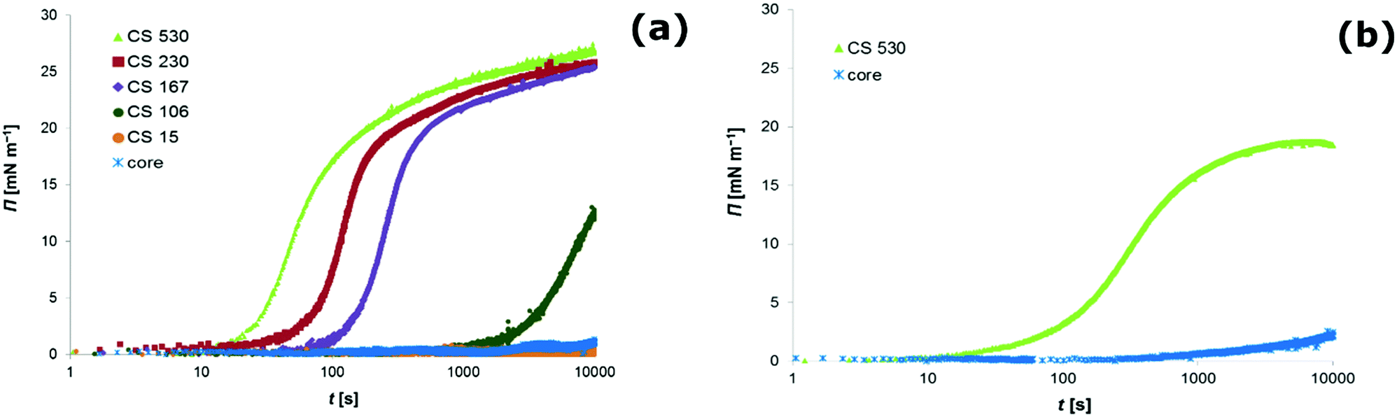 | ||
| Fig. 1 Evolution of the surface pressure Π as a function of time t as measured by pendant drop tensiometry at the air–water interface (a) and at the hexane–water interface (b). The surface pressure development is attributed to the interfacial adsorption of particles from the bulk phase. Colloidal dispersions of core particles (core) and various core–shell (CS) particles with different shell dimensions are investigated. For all particle types, the experimental conditions are as follows: particle volume number density c∞ = 9.25 × 10¹⁵ m−3, bulk phase adjusted to pH 6 and 20 mM NaCl as a background electrolyte. | ||
For quantitative interpretation of these data, one has to be aware that the equation of state for interfacial particles is for the most part non-linear in the density, meaning that one cannot easily relate surface pressure to surface coverage.23 For molecular species at low surface coverage, when molecules do not interact with each other, the surface pressure development is described by the ideal gas law:
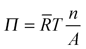 | (2) |
![[R with combining macron]](https://www.rsc.org/images/entities/i_char_0052_0304.gif) is the ideal gas constant and T is the temperature of the system. Assuming full coverage of the interface by particles with a diameter of one micrometre, one arrives according to eqn (2) at a surface pressure on the order 10−6 mN m−1 for a fully covered interface. The detection limit of the drop tensiometer is on the order of 10−4 mN m−1. Hence, the surface pressure we measure for micron-sized core–shell particles cannot be an ‘ideal gas’ pressure, rather, it must stem from the interaction between individual particles. One can safely say that any finite surface pressure measured must correspond to a situation where the surface coverage is significant and particles interact with each other via steric or electrostatic interactions.
is the ideal gas constant and T is the temperature of the system. Assuming full coverage of the interface by particles with a diameter of one micrometre, one arrives according to eqn (2) at a surface pressure on the order 10−6 mN m−1 for a fully covered interface. The detection limit of the drop tensiometer is on the order of 10−4 mN m−1. Hence, the surface pressure we measure for micron-sized core–shell particles cannot be an ‘ideal gas’ pressure, rather, it must stem from the interaction between individual particles. One can safely say that any finite surface pressure measured must correspond to a situation where the surface coverage is significant and particles interact with each other via steric or electrostatic interactions.
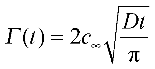
To estimate a timescale for a particle population to reach a certain surface coverage, the formula of Ward and Tordai can be used.27 The formula is valid if there is no adsorption barrier and colloidal particles are irreversibly adsorbed to the interface.
 | (3) |
 , where r is the hydrodynamic radius of the respective particle type. We choose the value of 0.05 for the surface coverage in order to yield a good fitting of our experimental data to the adsorption model; in a separate study we confirm that core–shell particles do indeed yield a finite surface pressure at such low surface coverage.28 For the diffusion constant D we use the values obtained by DLS. The volume number density c∞ was 9.25 × 10¹⁵ m−3 for each particle type. According to eqn (3) we calculate the corresponding theoretical timescales
  , the time it takes to reach a surface coverage Γ*/Γmax = 0.05 and compare these with tmeasured* obtained as shown in Fig. 1a. The value of tmeasured* is seen in Fig. 1a as the time point where the surface pressure Π reaches a value of 1 mN m−1. The results of our analysis are given in Table 2.
| Particle type | Γ* [m−2] | D [m2 s−1] | t measured* [s] | t theoretical* [s] |
|---|---|---|---|---|
| CS530 | 1.84 × 10¹⁰ | 2.20 × 10⁻¹³ | 16 | 14 |
| CS230 | 4.01 × 10¹⁰ | 3.42 × 10⁻¹³ | 27 | 43 |
| CS167 | 4.95 × 10¹⁰ | 3.79 × 10⁻¹³ | 95 | 59 |
| CS106 | 7.08 × 10¹⁰ | 3.79 × 10⁻¹³ | 1900 | 122 |
| CS15 | 1.09 × 10¹¹ | 5.77 × 10⁻¹³ | >10![[thin space (1/6-em)]](https://www.rsc.org/images/entities/char_2009.gif) 000 000 |
187 |
| Core | 1.18 × 10¹¹ | 5.96 × 10⁻¹³ | — | 213 |
Clearly, for the core–shell particles with a thick shell, theoretical and measured timescales for the development of a finite surface pressure are on the same order of magnitude. For the core–shell particles CS106 and CS15 with a thin shell and for the core particles, however, tmeasured* ≫ ttheoretical*. This picture is consistent with an energy barrier for interfacial adsorption. Such an energy barrier reduces the probability for particle attachment to the interface, thereby increasing the timescale for the development of a certain surface pressure.1
Our results suggest that the adsorption barrier, as existing for hard particles, seems to be substantially lowered, if not even absent, for the core–shell particles with a shell thickness above a given value. This value is larger than 100 nm for the core–shell particles investigated in this study. In contrast to hard particles, the core–shell particles seem to adsorb easily to the fluid interface once they reach the subsurface region.
We would like to note that electrolyte addition, a well-known way to promote interfacial adsorption of particles,15 did not seem to help interfacial adsorption of hard particles. We ascertained that for electrolyte concentrations up to 500 mM sodium chloride the very long timescales for surface pressure development by hard particles remain unchanged (data not shown). We also found that hard polystyrene particles with cationic surface charge hardly adsorbed onto fluid interfaces, but could be made to adsorb at fluid interfaces by growth of a soft shell around them (data not shown). These observations highlight the generality of the method to promote the interfacial adsorption of particles by means of a soft shell.
Microscopic analysis of core–shell particles at the fluid interface
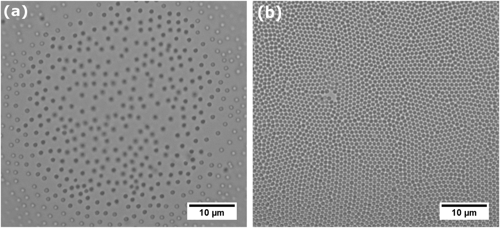
As the core–shell particles have a solid core with an index of refraction which differs markedly from the surrounding medium, they are well visible via light microscopy, in spite of their small size. This allowed us to conduct microscopic analysis to get an impression of the structure of the particle layer on the fluid interface. For the core particles without the soft shell, we could not detect any particles attached to the fluid interface over a period of one day. In fact, we observed that particles are depleted from the subsurface region due to sedimentation. For all the core–shell samples, however, we found that particles would readily adsorb to both the air–water (see Fig. 2a) and oil–water interface (see Fig. 2b). As we observed the samples under quiescent conditions, this adsorption process seems to occur without energy input, solely by diffusion. These observations are in agreement with the results we obtained from tensiometry. Note that core–shell particles CS15 did not show any surface pressure development over the time-scale depicted in Fig. 1a, but microscopy revealed a densely covered interface after a waiting time of one day. | ||
| Fig. 2 Microscopy picture of the air–water interface (a) and decane–water interface (b) after interfacial adsorption of core–shell particles CS530. The micrograph was obtained by light microscopy on an up-right microscope. The inset shows the calculated particle pair-correlation function g(r) normalized by the particle diameter. | ||
The particles in Fig. 2 can be seen to maintain distances of a few microns, which suggests that they interact by a long range repulsion. This repulsion may also impose a non-random structure; this is indeed visible in the pair correlation functions g(r) (insets). At the air–water interface, we find a pronounced peak, indicating repulsion over distances of microns, probably of electrostatic origin. At the decane–water interface, there is a weaker maximum in g(r), indicating a weaker repulsion.
To obtain more detailed information about the morphology of core–shell particles adsorbed to the air–water interface, we used cryo-SEM. The cryofixation procedure allows the samples to be frozen instantly, so that the structure of interfacially located core–shell particles can be maintained. Also using light microscopy only the core of the core–shell particles is visible, while using cryo-SEM also the structure of the soft shell can be ascertained.
From the SEM pictures it becomes evident that core–shell particles adopt a fried-egg like structure at the interface (see Fig. 3). Due to the higher electron density of the core compared to the shell, both parts of the core–shell particle can be distinguished. The core seems to have a rough surface, while the outer shell is more smooth. The dimension of the inner part with the rough surface equals the measured hydrodynamic diameter of the core particles, which gives further support that this part is the actual core particle. The fact that the core is visible in the SEM picture implies that the core of the core–shell particles protrudes into air. This is a striking feature, as the bare core particles without the shell cannot breach the interface. We note in passing that protrusion of the cores into the non-aqueous phase could cause de-swelling and collapse of the poly-NIPAM shell. We also notice that the core has a certain roughness, as if it was formed as a cluster of much smaller particles. This is in agreement with recent mechanistic insights into emulsion polymerization.29
 | ||
| Fig. 3 SEM micrograph obtained after interfacial adsorption of particles and cryo-fixation. The micrograph shows the interfacial structure of core–shell particles CS230 (a) and core–shell particles CS530 (b) adsorbed at the air–water interface. The visible shadows near the particles outside the perimeter appear due to sputter coating under an angle of 45° and signify that the particles protrude the fluid interface. | ||
The measurement of the overall particle dimensions in the SEM pictures reveals that the diameter of the core–shell particles at the interface is roughly equal to their hydrodynamic diameter as measured by DLS in the bulk. For the particles depicted in Fig. 3a we find a diameter of ∼1.3 μm at the air–water interface, and determined a hydrodynamic diameter of 1.3 μm by DLS. For another set of particles (see Fig. 3b) we measure a particle cross-sectional diameter of ∼1.9 μm at the air–water interface, and a hydrodynamic diameter of 1.9 μm by DLS. This means that our core–shell particles do not undergo significant radial stretching at the interface, in contrast to what is frequently reported for microgels.17,23 Radial stretching of the soft shell seems to be suppressed by the solid core.
Stabilization of bubbles and emulsion droplets by core–shell particles
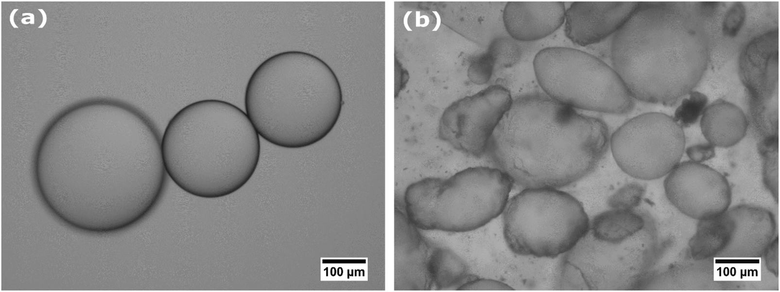
The facile adsorption of core–shell particles to fluid interfaces allowed for the preparation of emulsions and air bubbles by low energy input methods, such as gentle hand-shaking. The typical size of bubbles and droplets obtained is 20–200 μm in diameter. Microscopic investigation reveals that the produced bubbles and droplets are stabilized by a monolayer of core–shell particles (see Fig. 4). | ||
| Fig. 4 Interfacial structure of an air bubble (a) and decane-in-water droplet (b) stabilized by core–shell particles CS530. Micrographs are obtained by light microscopy. The micrographs reveal that bubbles and emulsion droplets are stabilized by an interfacial monolayer of core–shell particles. | ||
Apart from their facile adsorption to fluid interfaces, it is important for application purposes to check whether core–shell particles can effectively stabilize fluid interfaces against disproportionation and coalescence, and compare this with hard particles. For bubbles stabilized by core–shell particles we could still observe slow coarsening by disproportionation. The bubbles that we initially produced completely disappeared over a time frame of 2–3 days.
Oil-in-water emulsions of hexane, decane and toluene showed much higher stability against coalescence and disproportionation. Decane–water emulsion did not show any signs of coarsening. Hexane and toluene emulsion droplets, comprising oils with rather high solubility in the aqueous phase, undergo an initial phase of coarsening, thereafter they are completely stable. This final stable state may be reached via the following sequence of events. Shrinking of small droplets leads to the lateral compression of core–shell particles at the interface. The shrinkage of small droplets may stop when flat facets develop or when crumpling of the droplet interface leads to the occurrence of areas with convex and concave curvatures, thus zero mean curvature, on the same droplet. The latter situation can arise after jamming and further lateral compression of the interfacial particles.30 In contrast, larger droplets grow in size. During the course of droplet growth, the particle surface coverage decreases. Insufficient coverage with particles will promote coalescence of the larger droplets, thereby effectively decreasing the interfacial area.31,32 After a coalescence event, the effective surface coverage of the newly created droplet may exceed 100% which then leads to the adoption of non-spherical droplet shapes, crumpling of the droplet interface, and occurrence of flat facets, similar to the situation described for shrinking droplets. The net result of these processes is that the surface coverage of the emulsion droplets increases and droplets stop coarsening.33–35
Following the scenario described above, emulsion droplets may initially coarsen but then attain an interfacial monolayer of core–shell particles in which the soft shell is locally highly compressed, thereby enabling the establishment of a stress-bearing network at the interface which provides excellent stability against coarsening. This is indeed what we observe with hexane and toluene emulsion droplets covered by core–shell particles. As can be seen in Fig. 5, the structure of the core–shell particles at the liquid interfaces progresses from an uncompressed state (Fig. 5a) to strong lateral compression of the soft shell after 10 days of storage (see Fig. 5b). We also observed that initially spherical emulsion droplets attain pronounced non-spherical shapes (Fig. 6b), a property which is known for bubbles15 and emulsion droplets36 stabilized by hard particles. Thus, core–shell particles at the oil–water interface seem to combine two properties: the ability to spontaneously adsorb and the strong anchoring to the fluid interface. The question why core–shell particles can strongly anchor at the oil–water interface, but less so at the air–water interface cannot be answered yet.
 | ||
| Fig. 5 Interfacial structure of hexane-in-water emulsion droplets stabilized by core–shell particles CS230. Micrographs are obtained by light microscopy. The two micrographs show how the interfacial structure evolves with time. Picture (a) is taken directly after emulsion preparation and picture (b) after 10 days of storage at room temperature. | ||
 | ||
| Fig. 6 Microscopic structure of hexane-in-water emulsion droplets stabilized by poly-NIPAM microgels without the PS core (radius 792 nm) (a) and core–shell particles CS140 (b). While poly-NIPAM microgel stabilized emulsion droplets remain spherical, emulsion droplets stabilized by core–shell particles are adopting non-spherical shapes after 10 days of storage. | ||
Finally, we compare core–shell particles with conventional microgels without the hard core. With them we were able to stabilize bubbles and emulsion droplets as reported elsewhere.21,31,37 However, we find that microgel-covered air bubbles and hexane-in-water emulsion still undergo slow but continuous coarsening; during coarsening, bubbles and droplets remain spherical (see Fig. 6a), signalling a finite Laplace pressure. Hence, core-less soft particles are performing less well as stabilizers than core–shell particles. These observations seem to corroborate once more the conclusion that in order to stop coarsening and support non-spherical droplets, a colloidal amour of particles with low compliance is essential. Core–shell particles synthesized in this study seem to fulfill this requirement. Upon sufficient compression of their soft shell, they provide the necessary low compliance in order to allow the establishment of a solid-like interface which provides superior stability against Ostwald ripening of emulsion droplets.
Conclusions
In the present work we prepared micron-sized core–shell particles consisting of a hard polystyrene core plus a soft, poly-NIPAM based shell. By varying the number of seed particles during precipitation polymerization, the dimension of the NIPAM shell could be varied from 15 nm up to 530 nm. Interfacial adsorption of these core–shell particles was investigated by microscopy and tensiometry and provided evidence that the larger core–shell particles easily adsorb onto the air–water interface. For core–shell particles with shell dimensions smaller than 100 nm, the adsorption rates were somehow reduced, which suggests that core–shell particles with a thin shell still possess a finite barrier for interfacial adsorption, nevertheless they could adsorb to the air–water interface. Hard polystyrene core particles, in contrast, seem to experience such a pronounced energy barrier for interfacial adsorption that they did not adsorb at all.The absence of a pronounced energy barrier for interfacial adsorption of core–shell particles allowed for facile, low energy-input production of bubbles and emulsion droplets stabilized by particles. Emulsions stabilized by core–shell particles showed good stability against coalescence and disproportionation. Bubbles stabilized by core–shell particles still underwent coarsening albeit slowly.
Remarkably, emulsion droplets stabilized by core–shell particles can adopt pronounced non-spherical shapes. This shows that core–shell particles strongly anchor to the fluid interface and that the hard core provides enough rigidity to the core–shell particles in order to allow the establishment of a stress bearing network which can sustain non-isotropic stresses present on non-spherical emulsion droplets. Consequently core–shell particles combine the advantageous properties of soft and hard particles: they can adsorb spontaneously to fluid interfaces, yet, anchor strongly at the interface and provide enough resistance against lateral compression due to disproportionation. Altogether our results show great promise for the application of core–shell particles to stabilize fluid interfaces as present in foams and emulsions.
References
- S. Tcholakova, N. D. Denkov and A. Lips, Phys. Chem. Chem. Phys., 2008, 10, 1608–1627 RSC.
- R. Aveyard, B. P. Binks and J. H. Clint, Adv. Colloid Interface Sci., 2003, 100, 503–546 CrossRef.
- B. P. Binks, R. Murakami, S. P. Armes, S. Fujii and A. Schmid, Langmuir, 2007, 23, 8691–8694 CrossRef CAS PubMed.
- Z. Du, M. P. Bilbao-Montoya, B. P. Binks, E. Dickinson, R. Ettelaie and B. S. Murray, Langmuir, 2003, 19, 3106–3108 CrossRef CAS.
- J. I. Park, Z. Nie, A. Kumachev, A. I. Abdelrahman, B. P. Binks, H. A. Stone and E. Kumacheva, Angew. Chem., 2009, 121, 5321 CrossRef.
- A. Stocco, W. Drenckhan, E. Rio, D. Langevin and B. P. Binks, Soft Matter, 2009, 5, 2215–2222 RSC.
- N. P. Ashby and B. P. Binks, Phys. Chem. Chem. Phys., 2000, 2, 5640–5646 RSC.
- S. L. Kettlewell, A. Schmid, S. Fujii, D. Dupin and S. P. Armes, Langmuir, 2007, 23, 11381–11386 CrossRef CAS PubMed.
- R. W. Style, L. Isa and E. R. Dufresne, Soft Matter, 2015, 11, 7412–7419 RSC.
- A. R. Abate, L. Han, L. H. Jin, Z. G. Suo and D. A. Weitz, Soft Matter, 2012, 8, 10032–10035 RSC.
- S. Tan, R. L. Sherman and W. T. Ford, Langmuir, 2004, 20, 7015–7020 CrossRef CAS PubMed.
- S. U. Pickering, J. Chem. Soc., Trans., 1907, 91, 2001–2021 RSC.
- A. B. Subramaniam, M. Abkarian and H. A. Stone, Nat. Mater., 2005, 4, 553–556 CrossRef CAS PubMed.
- A. V. Nguyen, P. George and G. J. Jameson, Chem. Eng. Sci., 2006, 61, 2494–2509 CrossRef CAS.
- C. Buchcic, R. H. Tromp, M. B. Meinders and M. A. Cohen Stuart, Soft Matter, 2015, 11, 1326–1334 RSC.
- R. Pelton, Adv. Colloid Interface Sci., 2000, 85, 1–33 CrossRef CAS PubMed.
- K. Geisel, L. Isa and W. Richtering, Langmuir, 2012, 28, 15770–15776 CrossRef CAS PubMed.
- W. Richtering, Langmuir, 2012, 28, 17218–17229 CrossRef CAS PubMed.
- T. Liu, S. Seiffert, J. Thiele, A. R. Abate, D. A. Weitz and W. Richtering, Proc. Natl. Acad. Sci. U. S. A., 2012, 109, 384–389 CrossRef CAS PubMed.
- B. Brugger, J. Vermant and W. Richtering, Phys. Chem. Chem. Phys., 2010, 12, 14573–14578 RSC.
- M. Destribats, V. Lapeyre, M. Wolfs, E. Sellier, F. Leal-Calderon, V. Ravaine and V. Schmitt, Soft Matter, 2011, 7, 7689–7698 RSC.
- J. Zhang and R. Pelton, Langmuir, 1999, 15, 8032–8036 CrossRef CAS.
- O. S. Deshmukh, A. Maestro, M. H. G. Duits, D. van den Ende, M. C. Stuart and F. Mugele, Soft Matter, 2014, 10, 7045–7050 RSC.
- A. Perro, G. Meng, J. Fung and V. N. Manoharan, Langmuir, 2009, 25, 11295–11298 CrossRef CAS PubMed.
- N. B. Vargaftik, B. N. Volkov and L. D. Voljak, J. Phys. Chem. Ref. Data, 1983, 12, 817–820 CrossRef CAS.
- J. Saien, A. Rezvani Pour and S. Asadabadi, J. Chem. Eng. Data, 2014, 59, 1835–1842 CrossRef CAS.
- A. F. H. Ward and L. Tordai, J. Chem. Phys., 1946, 14, 453–461 CrossRef CAS.
- C. Buchcic, R. H. Tromp, M. B. Meinders and M. A. Cohen Stuart, manuscript in preparation.
- M. E. Dobrowolska, J. H. van Esch and G. J. M. Koper, Langmuir, 2013, 29, 11724–11729 CrossRef CAS PubMed.
- M. Abkarian, A. B. Subramaniam, S. H. Kim, R. J. Larsen, S. M. Yang and H. A. Stone, Phys. Rev. Lett., 2007, 99, 188301 CrossRef PubMed.
- M. Destribats, V. Lapeyre, E. Sellier, F. Leal-Calderon, V. Schmitt and V. Ravaine, Langmuir, 2011, 27, 14096–14107 CrossRef CAS PubMed.
- F. Leal-Calderon and V. Schmitt, Curr. Opin. Colloid Interface Sci., 2008, 13, 217–227 CrossRef CAS.
- R. M. Wiley, J. Colloid Sci., 1954, 9, 427–437 CrossRef CAS.
- S. Arditty, C. P. Whitby, B. P. Binks, V. Schmitt and F. Leal-Calderon, Eur. Phys. J. E: Soft Matter Biol. Phys., 2003, 11, 273–281 CrossRef CAS PubMed.
- B. Madivala, S. Vandebril, J. Fransaer and J. Vermant, Soft Matter, 2009, 5, 1717–1727 RSC.
- S. A. F. Bon, S. D. Mookhoek, P. J. Colver, H. R. Fischer and S. van der Zwaag, Eur. Polym. J., 2007, 43, 4839–4842 CrossRef CAS.
- M. Destribats, M. Wolfs, F. Pinaud, V. Lapeyre, E. Sellier, V. Schmitt and V. Ravaine, Langmuir, 2013, 29, 12367–12374 CrossRef CAS PubMed.
| This journal is © The Royal Society of Chemistry 2017 |