DOI:
10.1039/C6SM00920D
(Paper)
Soft Matter, 2017,
13, 101-110
Apparent contact angle and contact angle hysteresis on liquid infused surfaces
Received
18th April 2016
, Accepted 18th May 2016
First published on 18th May 2016
Abstract
We theoretically investigate the apparent contact angle and contact angle hysteresis of a droplet placed on a liquid infused surface. We show that the apparent contact angle is not uniquely defined by material parameters, but also has a dependence on the relative size between the droplet and its surrounding wetting ridge formed by the infusing liquid. We derive a closed form expression for the contact angle in the limit of vanishing wetting ridge, and compute the correction for small but finite ridge, which corresponds to an effective line tension term. We also predict contact angle hysteresis on liquid infused surfaces generated by the pinning of the contact lines by the surface corrugations. Our analytical expressions for both the apparent contact angle and contact angle hysteresis can be interpreted as ‘weighted sums’ between the contact angles of the infusing liquid relative to the droplet and surrounding gas phases, where the weighting coefficients are given by ratios of the fluid surface tensions.
1 Introduction
A novel class of functional surfaces has recently been introduced, known as liquid infused surfaces1 (LIS), lubricant impregnated surfaces2 (LIS), or slippery liquid infused porous surfaces3 (SLIPS). They are typically constructed by infusing rough or porous materials with lyophilic oils. Thus, as shown in Fig. 1, a typical liquid infused system involves three fluids: the oil phase, and typically a (water) droplet in a gas environment. They have been shown to exhibit many advantageous wetting properties, including low contact angle hysteresis, self-cleaning, drag reduction, anti-icing and anti-fouling.1–7 Furthermore, compared to competing technologies such as superhydrophobic surfaces, LIS are robust against pressure-induced instabilities and failure,8–11 which makes them favourable for applications to a wide-range of problems, ranging from marine fouling and product packaging to heat exchanger and medical devices.1,12,13
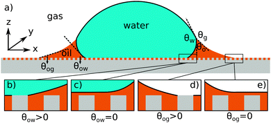 |
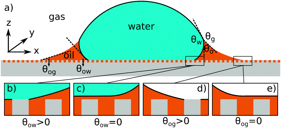
| | Fig. 1 (a) The geometry of an axisymmetric water droplet placed on a liquid infused surface, indicating the three Neumann angles θo, θw and θg, and the wetting angles relative to the oil phase θow and θog. Depending on the oil–water contact angle, the water droplet can touch the solid substrate (b) or be separated by a thin oil layer (c). Similarly, the oil–gas contact angle determines whether the infusing oil merely hemi-wicks the rough surface (d) or coat the surface corrugations (e). Based on the combinations of (b and c) and (d and e), four wetting states of interest on liquid infused surfaces can be distinguished. | |
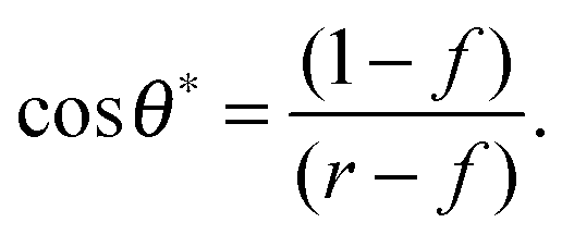
For LIS, oil penetration in between the surface corrugations is key. As such, the material contact angles characterizing the infusing oil relative to the air and water phases have to satisfy two wicking criteria: θYow < θ* for the oil–water and θYog < θ* for the oil–gas interfaces. In general the critical angle θ* will depend on the details of the surface corrugations,14 but in many cases of interest a simple thermodynamic criterion can be expressed in terms of global statistical quantities. These are the roughness factor r, corresponding to the ratio of total area of the textured surface to its projected area, and the fraction f of the projected area that is occupied by a solid15,16
| |  | (1) |
It is worth noting that, even with these thermodynamic criteria satisfied, impalement of the water and gas phases may still occur at high pressures,
8–10 but we will exclude such cases here.
For vanishing contact angles θYow = 0° or θYog = 0°, it is possible that a thin oil layer will completely cover the surface roughness. Provided the wicking criteria are satisfied, we can identify four relevant thermodynamic wetting states.2 As illustrated in Fig. 1(b–e) these states depend on the presence and absence of a thin oil film between the water and/or gas phases and the solid surface. The presence of a thin oil film prevents a direct contact between the water/gas phase and the solid. It has been proposed to explain the smooth displacement of contact lines on liquid infused surfaces,17 as opposed to stick-slip commonly observed on other surfaces.18
While thermodynamics arguments are sufficient to predict the presence of different wetting states on LIS, to date there is no theory for computing the corresponding values of the contact angle and contact angle hysteresis, despite their relevance as key design parameters for any application. For example, low contact angle and low contact angle hysteresis are preferred for efficient heat transfer,13,19 while high contact angle and low contact angle hysteresis are desirable for high droplet mobility.20
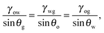
For standard wetting scenarios, the Young's equation determines how the contact angle depends on the three independent (solid–liquid, solid–gas and liquid–gas) surface tensions. In contrast, there are six independent surface tensions for LIS, and an equivalent relation for the contact angle as a function of these surface tensions is, to date, not yet available. We will derive such a relation in this paper. Furthermore, an oil ridge is drawn to the oil–water–gas three-phase contact line in LIS system due to capillary action, as depicted in Fig. 1(a). It is unclear how the shape and size of this ridge can be controlled, and correspondingly what the consequences might be. Indeed, a distinguishing feature of LIS we will show here is that both the apparent contact angle and contact angle hysteresis are not uniquely defined by material parameters; instead, they also have a strong dependence on the size of the oil ridge relative to the droplet, which in return can be manipulated by tuning the oil pressure.
This paper is organised as follows. In Section 2, we will list the essential physical assumptions for the theoretical model and describe the computational method we employ to calculate drop morphologies on liquid infused surfaces. We will derive a closed form expression for the contact angle in the limit of vanishing oil ridge in Section 3. In Section 4, supported by numerical calculations, we will address the influence of oil pressure on the apparent contact angle. In Section 5, we will discuss how the theoretical results in Sections 3 and 4 can be extended to predict contact angle hysteresis generated by contact line pinning at the edges of the surface corrugations. Finally, we will conclude and describe future works in Section 6.
2 Physical model and numerical method
2.1 Physical model
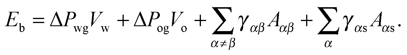
For concreteness, let us consider a typical LIS system consisting of a water droplet (w) deposited on a porous/rough solid substrate (s) infused by an oil liquid (o), and immersed in a surrounding gas phase (g) as shown in Fig. 1. Our theory is valid, without any loss of generality, if other fluids are used instead of water, oil and gas. Let us also define γwg, γow and γog as the surface tensions between the water–gas, oil–water and oil–gas components respectively. We further assume that the typical length scales in the problem (the droplet size, the oil ridge, and the surface corrugation) are smaller than the capillary length, such that we can neglect gravity. For water and most oils, the capillary length is of the order of a few millimetres.
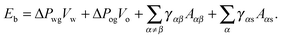
The total energy Eb has several different contributions. First, this energy contains two terms that depend on the volumes of the water droplet Vw and infusing oil Vo, and on the pressure differences ΔPwg between the water droplet and the surrounding gas, and ΔPog between the oil and the surrounding gas. It is also convenient to define ΔPow as the pressure difference between oil and water. Second, each fluid–fluid interface contributes with a term proportional to γαβAαβ. The subscripts α,β correspond to the water, oil and gas phases. Third, if any of the phases is in contact with a portion of the solid substrate, it also contributes with a term γαsAαs, where s indicates the solid surface. Thus, the total energy is given by:
| |  | (2) |
Let us now discuss the suitable ensemble for the water and oil phases. Usually the volume of the water droplet is fixed in experiments. As such, in our calculations the pressure difference Δ
Pwg acts as a Lagrange multiplier to the droplet volume. For the oil phase, instead it is appropriate to assume the pressure ensemble due to the presence of a large amount of oil infused in between the surface corrugations, which to a good approximation can be considered as an infinite reservoir. In this context, the definition of
Vo in
eqn (2) corresponds to the amount of oil drawn from the reservoir into the ridge. The oil which fills the surface roughness is not included in the computation of
Vo.
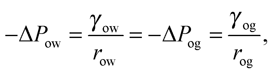
In equilibrium, the Laplace pressures of the fluid–fluid interfaces determine their mean curvatures κ through the Laplace law
As before, the subscripts
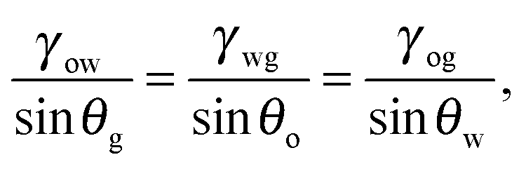
α,β correspond to the water, oil and gas phases. At the triple point junction, where the three fluid interfaces meet, the stresses are balanced
| |  | (4) |
As shown in
Fig. 1(a),
eqn (4) leads to the Neumann angles,
21θo,
θw and
θg, where
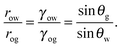
| |  | (5) |
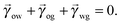
and
θo +
θw +
θg = 2π. It is worth noting that, for
γwg >
γow +
γog, the water droplet is encapsulated by a thin layer of oil, and
eqn (5) is ill-defined. In this work, we will exclude such a case, and assume that the Neumann angles can be computed according to
eqn (5) for a given set of water–gas, oil–gas, and water–oil surface tensions.
The interaction between the ternary fluids (water–oil–gas) with the (smooth) solid surface can be characterised by three material contact angles, θYwg, θYow and θYog, given by the Young's relation
| | 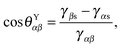 | (6) |
where once again the subscripts
α,β correspond to the water, oil and gas phases. For liquid infused surfaces, the solid surface is not smooth. In fact, the surface roughness is key for maintaining the infusing oil. As shown in
Fig. 1, a typical substrate can be modelled as a composite between solid and oil. If pinning effects and the related energy barriers are negligible, the contact angles can be described by weighted averages as proposed by Cassie and Baxter,
22| | cos![[thin space (1/6-em)]](https://www.rsc.org/images/entities/char_2009.gif) θCBαβ = fcosθYαβ + (1 − f), θCBαβ = fcosθYαβ + (1 − f), | (7) |
where
α represents the oil phase,
β is either the water or gas phase, and
f is the fraction of the projected solid area exposed to the water or gas phase. We will explicitly consider pinning phenomena at the sharp edges of the surface roughness in Section 5, where we address the emergence of contact angle hysteresis on LIS. Formally the weighted average will enter the total energy
Eb by redefining the surface energy of the composite substrate
γαs →
fγαs + (1 −
f), where
α represents the water or gas phase. For the Cassie–Baxter equation to be valid, the water droplet needs to cover a sufficiently large number (
e.g. several tens) of posts.
As it is not the aim of this work to resolve the liquid morphology down to the molecular scale, we will not specifically model a thin oil film on top of the roughness, because the effect of a thin microscopic film on the equilibrium shape of a macroscopic droplet is negligible. Its presence, however, will affect the choice of θYow and θYog. Typically it is convenient to assume the value of 0° when a thin wetting oil film is present, though in general a thin oil film does not necessarily lead to vanishing contact angles, depending on the effective interfacial potentials describing the intermolecular forces acting between the substrate and the water and oil molecules.23,24
2.2 Numerical method
In our calculations we assume the distortion induced by the underlying pattern geometry to be negligible and the drop to retain an axial symmetry. We will numerically compute droplet configurations by employing a finite element approach based on the free software SURFACE EVOLVER.25Eqn (2) will be minimized according to standard minimisation algorithms. Without losing generality, we will set the reference pressure of the gas phase to zero, while the pressures of the water and oil phases will correspond to the Laplace pressures of the water–gas and oil–gas interfaces. The oil phase will be controlled by its pressure ΔPog, by including the corresponding term in the total energy in eqn (2), while the volume Vw of the water droplet will be imposed by a global constraint. The Laplace pressure ΔPwg is the Lagrange multiplier to the constant droplet volume constraint.
3 The limit of vanishing oil ridge
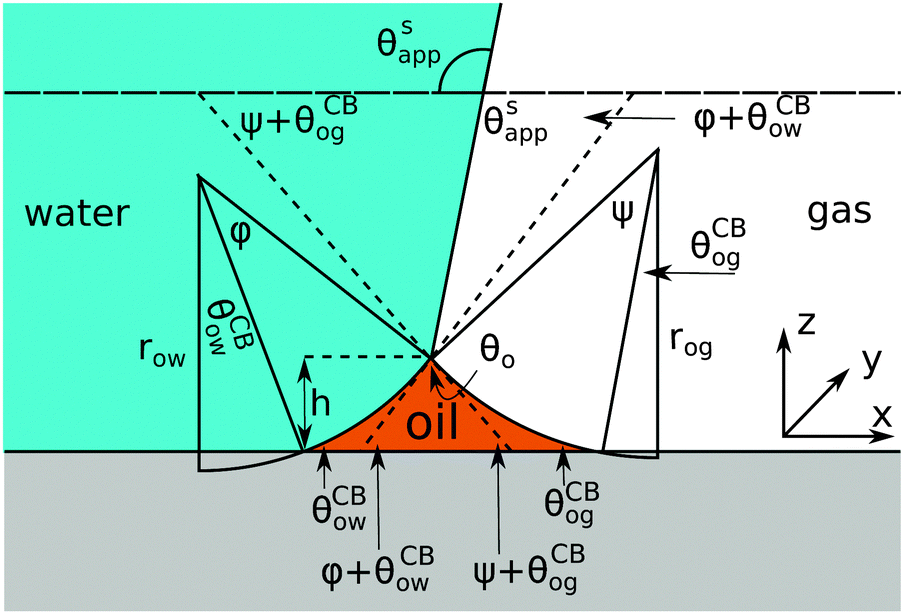
In the most general case, the shapes of fluid–fluid interfaces with constant mean curvature and an axial symmetry must belong to the family of Delaunay surfaces.26 In our problem, the water–gas interface will be a portion of sphere, while the oil–water and oil–gas interfaces can be described either by nodoids or unduloids, depending on the boundary conditions (wetting contact angles). In this section we are interested in the case where the size of the oil ridge is infinitely small compared to the water drop. For most liquid infused surfaces, this limit is equivalent to the condition of large and negative oil pressure in comparison to the Laplace pressure in the water droplet, −ΔPwg/ΔPog → 0, since ΔPog < 0 is the regime of physical interest. In Section 4, we will comment on the implications related to the case of ΔPog > 0. In the −ΔPwg/ΔPog → 0 limit, the geometry near the oil ridge can be simplified. The water–gas interface is effectively flat. The curvature in the x − y plane for the oil–water and oil–gas interfaces can be neglected. Their profiles in the x − z plane are circular arcs to an excellent approximation.
Referring to the sketch shown in Fig. 2, we introduce two auxiliary angles φ and ψ for the water-oil and oil–gas interfaces. These interfaces respectively have radii of curvature row and rog. The oil–water and oil–gas interfaces approach the substrate with contact angles θCBow and θCBog. Since −ΔPwg/ΔPog → 0, we can deduce that
| |  | (8) |
which, combined with
eqn (5), leads to
| |  | (9) |
In
Fig. 2, we can identify a triangle with interior angles given by
φ +
θCBow,
ψ +
θCBog and
θo. Imposing their sum to be π, we have a trigonometrical relation
| | | φ + θCBow + ψ + θCBog + θo = π. | (10) |
Similarly we can derive geometrical relations for the apparent contact angle
θSapp:
| | | θSapp = θw − θCBow − φ = π − θg + θCBog + ψ. | (11) |
Here we have used the superscript
S to denote the limiting case of vanishing oil volume. To complete the set of equations and express
θSapp in terms of the remaining material parameters, we can deduce one more equation by comparing the expressions for the height
h given by both menisci,
| h = rog[cosθCBog − cos(ψ + θCBog)] |
| | | = row[cosθCBow − cos(φ + θCBow)]. | (12) |
Substituting
eqn (9)–(11) into
eqn (12), we obtain
| sinθw[cosθCBog + cos(θSapp + θg)] |
| | | = sinθg[cosθCBow − cos(θw − θSapp)]. | (13) |
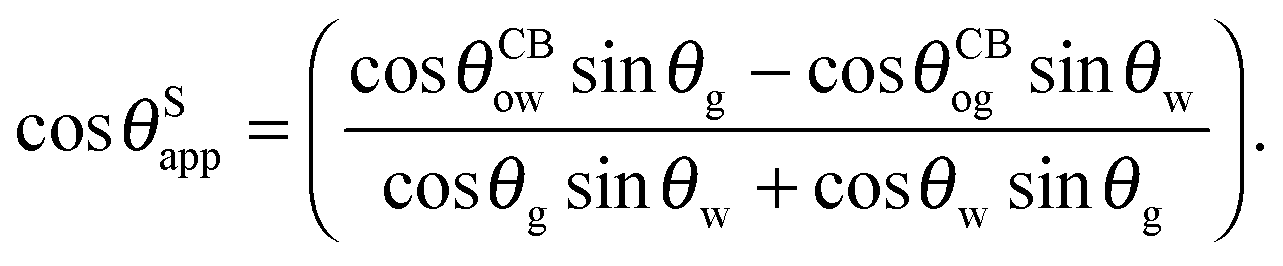
Eqn (13) can be inverted to express
θSapp only in terms of the Neumann, oil–water and oil–gas contact angles:
| |  | (14) |
Note that the specific value of the Laplace pressures for the oil–water and oil–gas interface do not appear in
eqn (14).
 |
| | Fig. 2 Sketch illustrating the derivation of the closed form expression for θSapp. In the limit of small oil ridge the water–gas interface is flat in proximity of the Neumann triangle, while the oil–water and oil–gas interfaces can be approximated by circular arcs. The surface corrugation is not explicitly depicted in this sketch. However, its effect is accounted by using the Cassie-Baxter's rather than the Young's angles for the oil–water and oil–gas interfaces. | |
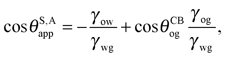
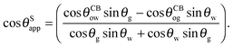
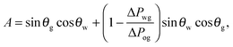
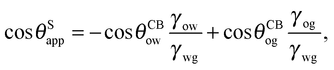
It is convenient to express the apparent contact angle in eqn (14) in terms of the fluid–fluid surface tensions and the oil–water and oil–gas contact angles. This is the form in which the material properties are most commonly reported and tabulated. To do this, we observe that the denominator in eqn (14) can be simplified as sin(θg + θw) = sin(2π − θo) = −sin(θo). Taking further advantage of eqn (5), we obtain
| | 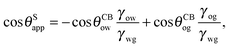 | (15) |
or alternatively
| | 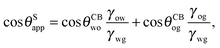 | (16) |
where we have used cos
θCBwo = −cos
θCBow.
In general eqn (15) can be interpreted as a ‘weighted sum’ between the oil–water and oil–gas contact angles, where the weighting coefficients are given by ratios of the fluid–fluid surface tensions. Several limiting cases are worth being pointed out: (i) when the oil–gas surface tension is very small, such that γog → 0 and γow → γwg, we recover cosθSapp = −cosθCBow = cosθCBwo. This is the Cassie–Baxter contact angle for a water droplet on a composite solid–oil substrate; (ii) Similarly, in the limit of γow → 0 and γog → γwg, we recover the Cassie–Baxter angle, cosθSapp = cosθCBog; (iii) for θCBow → 0 and θCBog → 0, we recover a condition equivalent to the Young's equation, cosθSapp = (γog − γow)/γwg, corresponding to a water droplet spreading on a flat substrate made of oil; (iv) the apparent contact angle approaches θSapp ∼ 90° if the oil–gas and oil–water interfaces have ‘symmetric’ properties, γog ∼ γow and θCBow ∼ θCBog, irrespective of their actual values.
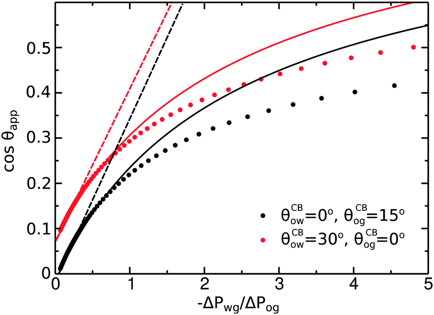
4 Role of the Laplace pressures
In the previous section we derived an analytical expression for the apparent contact angle θSapp in the limit of small oil ridge, assuming a vanishing Laplace pressure for the water–gas interface. In this section we will extend our analysis to the general case, explicitly accounting for the role of finite Laplace pressures for the three interfaces. In particular we will show that θapp is not uniquely determined by the material parameters, but it is affected by the relative size of the oil ridge relative to the size of the water drop.
To illustrate the role of the Laplace pressures, we have numerically computed ternary drop morphologies for representative systems typical of an oil with low surface tension, choosing θo = 30° and symmetrically θw = θg = 165° (see Fig. 4). We consider two different combinations of wetting angles for the oil phase, given by (i) θCBow = 0°, θCBog = 15° and (ii) θCBow = 30°, θCBog = 0°. We then vary the oil pressure while keeping the water volume constant. In our calculations the specific value of the volume is not relevant, as it simply sets the length scale of the system.
In the presence of finite Laplace pressures it is necessary to adapt the definition of θapp as the water–gas interface is no longer represented by a straight line. Two meaningful geometric choices are possible as shown in Fig. 3, either (i) as the slope of the water–gas interface at the triple junction θapp, or (ii) as the slope of the virtual water–gas interface as it is extrapolated down to the solid substrate  . The water–gas interface assumes a spherical cap geometry and the extrapolation procedure is unique. We find
  . In the limit of vanishing oil ridge, both definitions converge to the same value corresponding to eqn (16), which describes the energy balance at the contact line. The deviation grows larger with increasing size of the ridge.
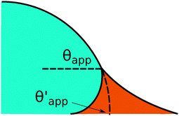 |
| | Fig. 3 Sketch of a drop with finite oil ridge displaying two possible definitions for the apparent angle: θapp at the triple junction of the fluid phases and  at the virtual contact line where the interpolated water–gas interface meets the solid substrate. at the virtual contact line where the interpolated water–gas interface meets the solid substrate. | |
In this work we favour the apparent contact angle definition at the triple junction, θapp, for two main reasons: (a) the angle at the Neumann triangle can be easily identified from the kink in the drop profile, and it can be directly measured both in simulations and experiments, and (b) it represents a direct measure of the rigid rotation of the Neumann triangle with respect to the solid surface. In contrast,  describes the slope of a portion of an interface that is only virtual, and cannot be measured directly.
The sequence of morphologies reported in Fig. 4(b–d) shows the impact of increasing −ΔPwg/ΔPog to the growth of the oil ridge. As depicted in Fig. 4(a), for the chosen sets of parameters, this is accompanied with a decrease in θapp, as consequence of the rigid rotation of the Neumann triangle (see the insets). For the two specific examples we have shown here, the variation in the apparent contact angle between −ΔPwg/ΔPog → 0 (small ridge) and −ΔPwg/ΔPog → ∞ (large ridge) is above 30°. Similarly  also decreases with increasing −ΔPwg/ΔPog but its variation is considerably smaller, limited to a few degrees. It is worth noting that our definition for the apparent contact angle is intended to characterise not just the water droplet shape, but instead the combined water droplet-oil ridge configuration, which spreads out as −ΔPwg/ΔPog increases. In this context, θapp captures this behaviour better than
  . From here on, we will only focus on θapp.
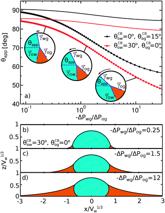 |
| | Fig. 4 Numerical results for a water droplet placed on liquid infused surfaces. The Neumann angles for the oil, water and gas phases are respectively θo = 30° and θw = θg = 165°. Two sets of wetting angles are considered: (i) θCBow = 0° and θCBog = 15°, and (ii) θCBow = 30° and θCBog = 0°. (a) Variation of the apparent contact angle as a function of −ΔPwg/ΔPog. The results for both definitions of apparent contact angles are shown, θapp (points) and  (straight lines). The insets illustrate how the Neumann triangles rotate as the oil pressure is varied. (b–d) Snapshots of numerically evaluated ternary drop configurations. (straight lines). The insets illustrate how the Neumann triangles rotate as the oil pressure is varied. (b–d) Snapshots of numerically evaluated ternary drop configurations. | |
One aspect differentiating the two combinations of angles reported in Fig. 4 is worth discussing further. In both cases the limit −ΔPwg/ΔPog → ∞ (i.e. ΔPog → 0) implies that the oil–gas ridge approaches a catenoid shape. However, while for finite contact angle θCBog the oil ridge has a finite size, in the case of θCBog = 0° the radius of the oil ridge is diverging. The latter corresponds to a liquid lens configuration, where the Neumann triangle is oriented such that the oil–gas interface is flat and lies parallel to the solid substrate.
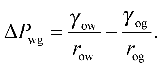
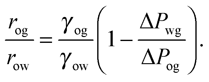
For small but finite −ΔPwg/ΔPog, we are also able to derive a closed form expression for the apparent contact angle θapp. To proceed, we note that the profiles of the oil–gas and oil–water interfaces can be still be assumed to be circular arcs in the x − z plane, as shown in Fig. 2. Following the convention displayed in Fig. 2, we have rog > 0 and row > 0 when ΔPog < 0 and ΔPow < 0. The curvature in the x − y plane can also be neglected for the oil–gas and oil–water interfaces. Taking into account the Laplace pressure difference (or the curvature) of the water–gas interface, we can write
| |  | (17) |
A straightforward manipulation invoking
eqn (3) leads to the following equation,
| |  | (18) |
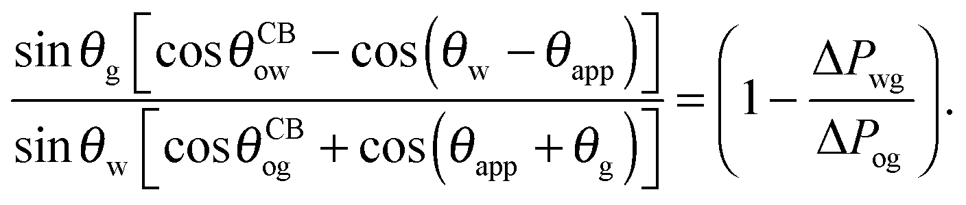
Following the same route leading to eqn (13) in the previous section, we can write down an equivalent relation with a correction term due to finite −ΔPwg/ΔPog,
| |  | (19) |
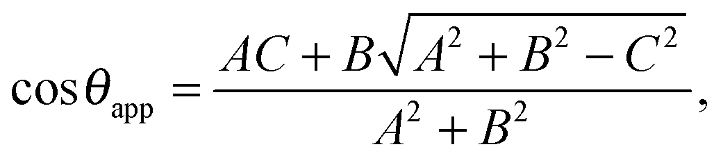
This relation can be inverted for the apparent contact angle, and it is given by
| |  | (20) |
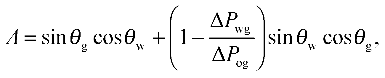
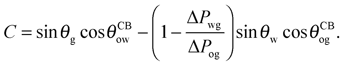
where
| |  | (21) |
| | 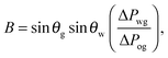 | (22) |
| |  | (23) |
As we can observe in
Fig. 5, the analytical expression compares well with the full numerical results for −Δ
Pwg/Δ
Pog < 1. For larger −Δ
Pwg/Δ
Pog, the model departs from the numerical solution, as the circular arc approximation for the oil–water and oil–gas interfaces breaks down.
 |
| | Fig. 5 Comparison between numerical results (dots), eqn (20) (full lines), and eqn (26) (dashed lines). The analytical expressions are valid for small −ΔPwg/ΔPog. The system parameters are the same as those reported in Fig. 4. | |
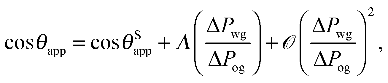
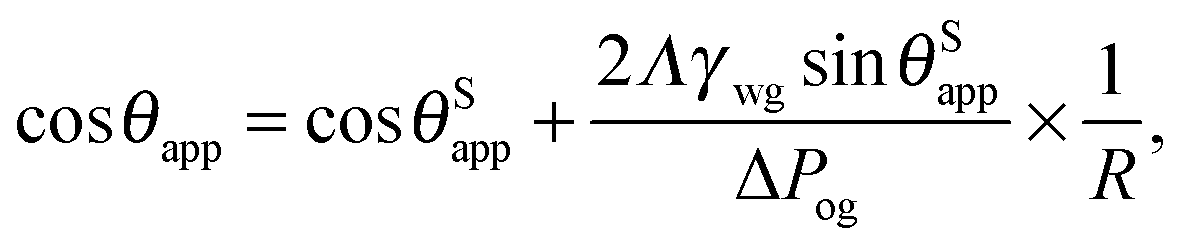
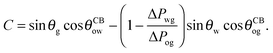
Furthermore, it is useful to extract a linear correction to the apparent contact angle due to the parameter −ΔPwg/ΔPog, given by
| |  | (24) |
with
| |  | (25) |
In experiments, the pressure difference between the oil and gas phases is usually kept constant. The Laplace pressure of the water droplet is given by ΔPwg = 2γwg/rwg ≃ 2γwgsinθSapp/R, where R/rwg ≃ sinθSapp is the effective contact radius, taken at the Neumann's triple junction between the water, oil and gas phases. Since we are only interested in the first order correction here, we have also approximated θapp ≃ θSapp. As such, eqn (24) can be written as
| | 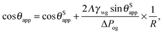 | (26) |
This equation has a familiar interpretation in the literature of wetting phenomena: it is reminiscent to the correction term in Young's angle due to line tension,
27,28 with an effective line tension given by
| | 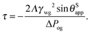 | (27) |
The linear approximation in
eqn (26) is also shown in
Fig. 5. It is in good agreement with the full numerical results for −Δ
Pwg/Δ
Pog < 0.5.
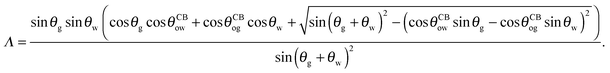
The coefficient Λ in eqn (25) can in principle assume both positive and negative values. It can be shown that Λ < 0 if θw + θg > π + θow + θog. Using the fact that θw + θg + θo = 2π, we obtain π > θo + θow + θog, which has a simple geometrical interpretation. From Fig. 6 it is clear that when θo + θow + θog = π the three angles of the oil ridge form a triangle. When Λ < 0 the sum of these angles is smaller than π, and the oil ridge is stable only if ΔPog < 0 and ΔPow < 0. In contrast, if Λ > 0, the sum of the three angles is larger than π, and the ridge is stable only if ΔPog > 0 and ΔPow > 0. Λ < 0 and ΔPog < 0 represent the most relevant physical regime for liquid infused surfaces. The case of Λ > 0 implies larger oil–water and oil–gas wetting angles, which are often in conflict with the wicking criterion in eqn (1). Additionally, for ΔPog > 0, the fluid configuration could be unstable against non-axisymmetric perturbations.29
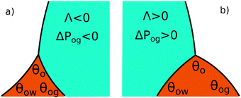 |
| | Fig. 6 Sketch illustrating the stable shapes of the oil ridge depending on the sign of Λ: (a) with Λ < 0 and ΔPog < 0; and (b) with Λ > 0 and ΔPog > 0. | |
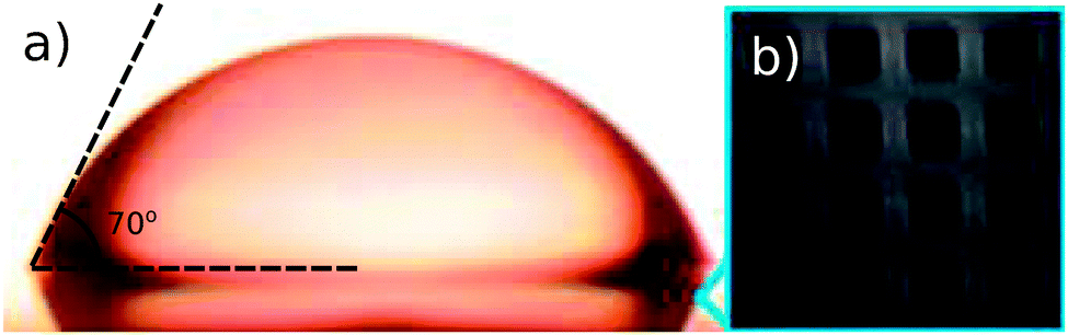
Taking advantage of eqn (15) and (27), we have computed the apparent contact angles and effective line tensions for several LIS systems reported in the literature2,3,30 in Table 1. In Fig. 7, we have also shown one experimental drop morphology from Smith et al.2 Here the oil ridge is small in comparison to the droplet size, and as such, we expect eqn (15) to provide an excellent approximation. Indeed the measured contact angle is in agreement with the theoretical prediction, assuming f = 0.44.
Table 1 Theoretical prediction for the apparent contact angle θSapp for several LIS systems reported in the literature,2,3,30 as given by eqn (15). For the Cassie–Baxter contact angles, we have assumed rough surfaces with projected solid area fraction f = 0.44. The surface tensions are expressed in the unit of mN m−1, the line tension τ is in Newton (N), and the angles are in degrees (°). Λ is the dimensionless parameter needed for computing the line tension as defined in eqn (25). For the computation of the line tension in eqn (27), we have assumed a typical Laplace pressure ΔPog = 103 Pa for the oil–gas ridge, corresponding to a radius of curvature, rog ∼ 100 μm
| Source |
Solid |
Droplet (w) |
Lubricant (o) |
γ
wg
|
γ
og
|
γ
wo
|
θ
w
|
θ
o
|
θ
g
|
θ
ow
|
θ
og
|
θ
Sapp
|
Λ
|
τ
|
|
Ref. 6
|
Inv. opal |
H2O |
Decanol |
30 |
28.5 |
8.6 |
108.3 |
88.4 |
163.3 |
0 |
0 |
48.4 |
−0.14 |
−1.9 × 10⁻⁷ |
|
Ref. 2
|
OTS |
H2O |
BMIm |
42 |
34 |
13 |
135.4 |
60.2 |
164.4 |
37 |
64 |
70.9 |
−0.15 |
−4.9 × 10⁻⁷ |
|
Ref. 3
|
S.Epoxy |
H2O |
FC-70 |
72.4 |
17.1 |
56.0 |
175.6 |
18.8 |
165.6 |
36.5 |
14.1 |
118.2 |
−0.29 |
−2.7 × 10⁻⁶ |
|
Ref. 3
|
Epoxy |
H2O |
FC-70 |
72.4 |
17.1 |
56.0 |
175.6 |
18.8 |
165.6 |
71.7 |
33.5 |
108.7 |
−0.24 |
−2.3 × 10⁻⁶ |
|
Ref. 3
|
Silicon |
C16 H34 |
H2O |
27.2 |
72.4 |
51.1 |
47.2 |
164.0 |
48.8 |
5.6 |
13.1 |
28.8 |
0.028 |
−2.0 × 10⁻⁸ |
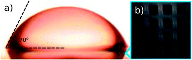 |
| | Fig. 7 (a) Experimental image of a water droplet on an OTS surface infused by BMIm as the lubricant, taken from Smith et al.2 The observed apparent contact angle θapp ≃ 70° ± 2° is in excellent agreement with the prediction of eqn (15)θSapp = 70.9°. (b) The surface pattern used in the experiment, again taken from Smith et al.2 From panel (b), we estimate that the projected solid fraction exposed to the water and gas phases is f = 0.44. | |
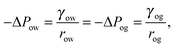
To compute the effective line tension in Table 1, we have assumed a typical Laplace pressure |ΔPog| = 103 Pa for the oil–gas ridge, corresponding to a radius of curvature of rog ∼ 100 μm. The computed effective line tension values are comparable to those measured for gas–liquid–solid contact line tensions.31 Noticeably, liquid infused surfaces always have negative effective line tensions since the signs of Λ and ΔPog are always the same for the system to be stable. Thus, the apparent contact angle of a water droplet on a liquid infused surface increases with increasing droplet volume. Our analytical expressions are readily applicable to other solid surfaces and fluids (both for the droplet and the lubricant) for cases where γwg < γow + γog.
5 Contact angle hysteresis
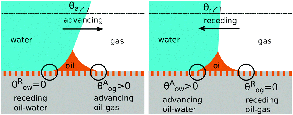
In the previous sections we computed the apparent contact angles in thermodynamic equilibrium, by introducing the Cassie–Baxter contact angles on the composite substrate. In this section we will address how pinning of the oil–water and oil–gas contact lines give rise to contact angle hysteresis on liquid infused surfaces. In general contact line pinning can be generated either by chemical heterogeneities or surface topographies.32–36 Here we will focus on the latter. Following the Gibbs condition,37 a pinned contact line does not exhibit a unique contact angle, instead it can take a range of values.
There are four wetting states on liquid infused surfaces: (i) When θCBow = θCBog = 0°, we expect the contact angle hysteresis to be negligible; (ii) in contrast, for θCBow > 0° and θCBog > 0°, the oil–water and oil–gas contact lines can both be pinned. As illustrated in Fig. 8, for a droplet to advance on a liquid infused surface, the oil–water contact line has to recede and the oil–gas contact line has to advance. Similarly, a receding droplet requires the oil–water contact line to advance and the oil–gas contact line to recede; (iii) for θCBow > 0° and θCBog = 0°, contact line pinning only occurs at the oil–water contact line, while (iv) for θCBow = 0° and θCBog > 0°, pinning only takes place for the oil–gas contact line.
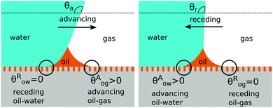 |
| | Fig. 8 Contact angle hysteresis on liquid infused surfaces arises due to the pinning of oil–water and oil–gas contact lines by the surface corrugations. Sketches illustrating the configurations of the oil ridge for (a) an advancing and (b) a receding water droplet. | |
In our model the contact angles are defined with respect to the oil phase, and are required to be small to guarantee the validity of the hemi-wicking criterion, eqn (1). The complementary angles, defined with respect to the water and gas phases are therefore large, and the analogy to superhydrophobic materials is appropriate.
A large body of work on contact angle hysteresis on superhydrophobic materials leads to the surprisingly simple result that the liquid (e.g. water) advancing contact angle occurs for θAwg = 180°,32,38 where deviations reported in literature are most likely due to experimental difficulties of measuring very large angles. The estimate for the receding angle is more debated, and several models have been proposed in the literature. These include (i) the sparse defect model proposed by Joanny and DeGennes,39 and experimentally tested by Reyssat and Quere,40 which suggests the receding contact angle has a logarithmic dependence with respect to the pillar spacing; (ii) thermodynamic approaches based on a linear average of the contact angle along the contact line,41 and (iii) the Cassie–Baxter model based on the area average.42 It is not in the scope of this work to assess the accuracy of such models in general, but we remark that the thermodynamic Cassie–Baxter approach is more aligned with the approximations assumed here. The sparse defect model is not consistent with the requirement of dense patterns, while the linear averaging model implies a strong effect of the orientation of the contact line on the global shape of a drop, which appears negligible in the currently available experimental data.17,38
Contact angle hysteresis is usually evaluated employing two alternative experimental approaches. The first one relies on applying a body force to the droplet,43 and the advancing and receding angles are measured at the front and back of the droplet just before it starts to move. To aid the discussion, let us now consider a specific example where the oil–water and oil–gas (Cassie–Baxter) contact angles are respectively θCBow = 30° and θCBog = 15°. The Neumann angles are chosen to be θo = 30° and θw = θg = 165°. Based on our discussion in the previous paragraph, the conditions for an advancing contact line are θRow = 0° and θAog = θCBog = 15°, while for a receding contact line we have θAow= θCBow = 30° and θRog = 0°. As such, the curves in Fig. 4 represent the advancing and receding apparent contact angles for a water drop on a liquid infused substrate with the aforementioned Cassie–Baxter contact angles, parametrized by the pressure ratio −ΔPwg/ΔPog. The contact angle hysteresis is defined as the difference between the advancing and receding contact angles, Δθapp = θAapp − θRapp, and it is shown in Fig. 9 as a function of −ΔPwg/ΔPog. The contact angle hysteresis shows a strong dependence on the pressure ratio (or equivalently the size of the oil ridge relative to the water droplet). It increases logarithmically in the limit of −ΔPwg/ΔPog → ∞, and it approaches a constant value as −ΔPwg/ΔPog → 0. Interestingly, the curve is also non monotonic, and exhibits a shallow minimum close to −ΔPwg/ΔPog = 0.2. This is in contrast with binary systems (e.g. water–gas on a solid surface), where the advancing and receding angles (correspondingly, contact angle hysteresis) can be regarded as constant material parameters.
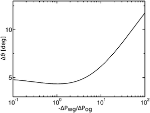 |
| | Fig. 9 Contact angle hysteresis (Δθ) of a water droplet on a liquid infused surface with θo = 30°, θw= θg = 165°, θCBow = 30° and θCBog = 15°. For this set of parameters, the two sets of data shown in Fig. 4(a) in fact correspond to the advancing (θRow = 0°, θAog = 15°) and receding (θAow = 30°, θRog = 0°) contact angles. We only focus on the definition of the apparent contact angle as defined at the triple junction, θapp. | |
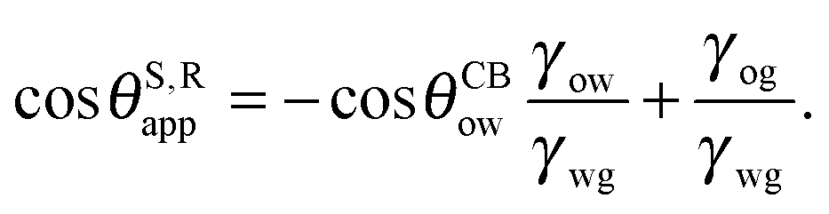
The analytical expressions in eqn (15), (20) and (26) can be modified to predict advancing and receding contact angles in the limit of small oil ridge, with the following replacement: θRow = 0°, θAow = θCBow, θAog = θCBog, θRog = 0°. In the limit of −ΔPwg/ΔPog → 0, we obtain
| |  | (28) |
and
| |  | (29) |
Furthermore, the resisting force due to contact angle hysteresis is given by
| | | F = 2RγwgΔcosθ, | (30) |
where
R is the contact radius and Δcos
θ = cos
θR − cos
θA. We can straightforwardly obtain the expression for Δcos
θSapp = cos
θS,Aapp − cos
θS,Rapp by combining
eqn (28) and (29). Here we assume the action of the body force does not significantly deform the droplet. The resulting closed form expression once again can be interpreted as a ‘weighted sum’ of the contact angle hysteresis for the oil–water and oil–gas contact lines. Similar expressions for Δcos
θapp can also be obtained for small but finite −Δ
Pwg/Δ
Pog by exploiting
eqn (20) or (26).
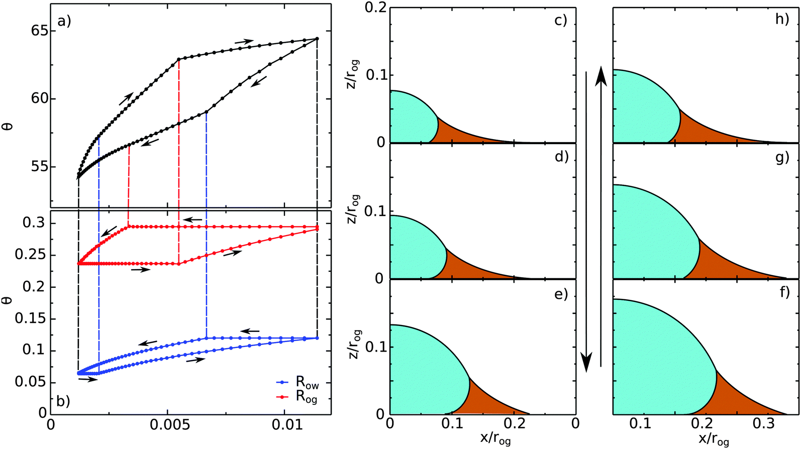
The second approach to measure contact angle hysteresis is by varying the volume of the water droplet.44 It is important to keep in mind that this protocol, unlike the previous one, involves measurements at different pressure ratio −ΔPwg/ΔPog. To elucidate the relevance of −ΔPwg/ΔPog, we report a typical hysteresis loop in Fig. 10. As before, we consider θCBow = 30°, θCBog = 15°, θo = 30° and θw= θg = 165° such that the data shown in Fig. 4(a) are the advancing and receding apparent contact angles as function of the pressure ratio for this set of parameters.
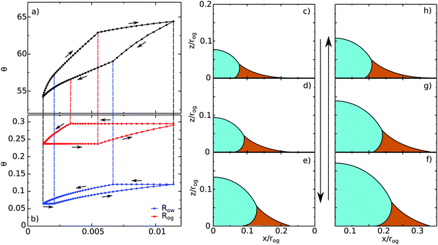 |
| | Fig. 10 A typical contact angle hysteresis loop for a water droplet on a liquid infused surface. Here θo = 30°, θw = θg = 165°, θCBow = 30° and θCBog = 15°. Panel (a) shows the apparent contact angle of the droplet as a function of its volume, while panel (b) shows the radii of the oil–water (Row) and oil–gas (Rog) contact lines. The oil pressure, ΔPog = −2γog/rog, is kept constant in these calculations, where Ro is the radius of curvature of the oil–gas interface. We use Ro to normalise the droplet volume and the contact line radii. (c–h) Drop morphologies as indicated in panels (a) and (b). | |
Let us begin with the drop configuration shown in panel (c) of Fig. 10. When the drop volume is increased, the apparent contact angle also increases. Here both the oil–water and oil–gas contact lines are pinned. At (d), the oil–water contact angle locally reaches 0°, and as a result, its contact line depins. With increasing the droplet volume, the oil–water contact line slides while the oil–gas one remains pinned. From configuration (e), both contact lines reach their corresponding advancing and receding contact angles, and become free to move. Correspondingly we observe a clear change of slope in the volume-contact angle relation. Once reaching (f), we reverse the process and decrease the droplet volume. Similar to the advancing scenario, initially both contact lines are pinned. As before, the depinning of the oil–water and oil–gas contact lines are not simultaneous, and occur at (g) for the oil–water contact line and at (h) for the oil–gas contact line. Both contact lines move freely from (h) to (c), which is our starting configuration.
6 Discussion
In this work we have theoretically investigated the apparent contact angle and contact angle hysteresis of a droplet on liquid infused surfaces (LIS). We derived a closed form expression for the apparent contact angle in the limit of vanishing oil ridge that captures the energy balance of the three fluid phases in contact with the solid substrate. Moreover, we computed the first order correction to the contact angle accounting for the influence of a small but finite oil wetting ridge surrounding the droplet, and showed that the correction term can be interpreted as a negative line tension. We also employed numerical calculations to explore the full range of negative oil–gas Laplace pressures, showing that the apparent contact angles indeed vary as a function of pressure. Unlike usual wetting scenarios involving two fluids (e.g. water–gas), the apparent contact angle for LIS cannot be regarded as a constant material property. We further note that our analytical expressions are in excellent agreement with the numerical results.
By introducing appropriate models for pinning and depinning of the oil–water and oil–gas contact lines, we showed how the analytical expression for the apparent contact angles can be readily manipulated to predict contact angle hysteresis on liquid infused surfaces. We presented a typical contact angle hysteresis loop, where we demonstrated that the depinning of the oil–water and oil–gas contact lines are in general not simultaneous. Contact angle hysteresis on LIS also depends on the oil pressure, or alternatively the relative size of the oil wetting ridge to the water droplet. Numerical calculations indicate that the contact angle hysteresis is smaller for large and negative oil pressure (small ridge), compared to small and negative oil pressure (large ridge). This finding provides a useful design principle for LIS, suggesting that the contact angle hysteresis can be tuned by the oil pressure, which can be achieved for example by under-filling/over-filling the substrate with oil.
Our results so far are limited to equilibrium morphologies. A full characterisation of wetting dynamics on liquid infused surfaces is an important and open problem. To this end, we recently developed a ternary free energy Lattice Boltzmann approach,45 well suited for handling the fluid dynamics of the water droplet and infusing oil, and for taking into account the Neumann angles and wetting contact angles involved in the problem. Another important direction for future work is to investigate the possible presence of thin oil film coating the surface corrugations and/or the water droplet,2 including the molecular mechanism that determines the film thickness and its influence to the shape of the water droplet when their length scales are comparable. When the infusing oil cloaks the droplet, the water–gas surface tension is not the appropriate variable to use in eqn (4), (15) and (26). Instead, it should be replaced by a composite water-oil and oil water interfaces, γwg → γow + γog − Δ(e), where the binding potential Δ(e) is a function of the oil film thickness, and its form depends on the intermolecular interactions of the fluids. We will explore this case in more details in future works.
Acknowledgements
C. S. and H. K. are grateful to Dr M. Brinkmann for inspiring comments on this manuscript, and thank Dr M. Wagner, Dr Y. Gizaw, Dr P. Koenig, Prof. G. Mistura and M. S. Sadullah for fruitful discussions. We acknowledge Procter and Gamble (P&G) for funding.
References
- A. K. Epstein, T.-S. Wong, R. A. Belisle, E. M. Boggs and J. Aizenberg, Proc. Natl. Acad. Sci. U. S. A., 2012, 109, 13182–13187 CrossRef CAS PubMed.
- J. D. Smith, R. Dhiman, S. Anand, E. Reza-Garduno, R. E. Cohen, G. H. McKinley and K. K. Varanasi, Soft Matter, 2013, 9, 1772–1780 RSC.
- T.-S. Wong, S. H. Kang, S. K. Y. Tang, E. J. Smythe, B. D. Hatton, A. Grinthal and J. Aizenberg, Nature, 2011, 477, 443 CrossRef CAS PubMed.
- A. Lafuma and D. Quéré, Europhys. Lett., 2011, 96, 56001 CrossRef.
- P. Kim, T.-S. Wong, J. Alvarenga, M. J. Kreder, W. E. Adorno-Martinez and J. Aizenberg, ACS Nano, 2012, 6, 6569–6577 CrossRef CAS PubMed.
- F. Schellenberger, J. Xie, N. Encinas, A. Hardy, M. Klapper, P. Papadopoulos, H.-J. Butt and D. Vollmer, Soft Matter, 2015, 11, 7617–7626 RSC.
- J. S. Wexler, I. Jacobi and H. A. Stone, Phys. Rev. Lett., 2015, 114, 1–5 CrossRef PubMed.
- H. Kusumaatmaja, M. L. Blow, A. Dupuis and J. M. Yeomans, Europhys. Lett., 2008, 81, 6 CrossRef.
- V. Hejazi and M. Nosonovsky, Langmuir, 2012, 28, 2173–2180 CrossRef CAS PubMed.
- H.-J. Butt, C. Semprebon, P. Papadopoulos, D. Vollmer, M. Brinkmann and M. Ciccotti, Soft Matter, 2013, 7615, 418–428 RSC.
- A. Tuteja, W. Choi, J. M. Mabry, G. H. McKinley and R. E. Cohen, Proc. Natl. Acad. Sci. U. S. A., 2008, 105, 18200–18205 CrossRef CAS PubMed.
- D. C. Leslie, A. Waterhouse, J. B. Berthet, T. M. Valentin, A. L. Watters, A. Jain, P. Kim, B. D. Hatton, A. Nedder, K. Donovan, E. H. Super, C. Howell, C. P. Johnson, T. L. Vu, D. E. Bolgen, S. Rifai, A. R. Hansen, M. Aizenberg, M. Super, J. Aizenberg and D. E. Ingber, Nat. Biotechnol., 2014, 32, 1134–1140 CrossRef CAS PubMed.
- R. Xiao, N. Miljkovic, R. Enright and E. N. Wang, Sci. Rep., 2013, 3, 1988 Search PubMed.
- C. Semprebon, P. Forsberg, C. Priest and M. Brinkmann, Soft Matter, 2014, 10, 5739–5748 RSC.
- J. Bico, U. Thiele and D. Quéré, Colloids Surf., A, 2002, 206, 41–46 CrossRef CAS.
- D. Quéré, Annu. Rev. Mater. Res., 2008, 38, 71–99 CrossRef.
- J. H. Guan, G. G. Wells, B. Xu, G. McHale, D. Wood, J. Martin and S. Stuart-Cole, Langmuir, 2015, 31, 11781–11789 CrossRef CAS PubMed.
- S. Varagnolo, D. Ferraro, P. Fantinel, M. Pierno, G. Mistura, G. Amati, L. Biferale and M. Sbragaglia, Phys. Rev. Lett., 2013, 111, 066101 CrossRef CAS PubMed.
- K. Rykaczewski, A. T. Paxson, M. Staymates, M. L. Walker, X. Sun, S. Anand, S. Srinivasan, G. H. McKinley, J. Chinn, J. H. J. Scott and K. K. Varanasi, Sci. Rep., 2014, 4, 4158 Search PubMed.
- L. Mahadevan and Y. Pomeau, Phys. Fluids, 1999, 11, 2449–2453 CrossRef CAS.
-
J. S. Rowlinson and B. Widom, Molecular Theory of Capillarity, Clarendon Press, Oxford, 1989 Search PubMed.
- A. B. D. Cassie and S. Baxter, Trans. Faraday Soc., 1944, 40, 546–551 RSC.
- R. Dufour, C. Semprebon and S. Herminghaus, Phys. Rev. E: Stat., Nonlinear, Soft Matter Phys., 2016, 93, 032802 CrossRef PubMed.
- I. Kuchin, O. Matar, R. Craster and V. Starov, Colloids Interface Sci. Commun., 2014, 1, 18–22 CrossRef CAS.
- K. A. Brakke, Philos. Trans. R. Soc., A, 1996, 354, 2143–2157 CrossRef.
- C. Delaunay, J. Math. Pures Appl., 1841, 6, 309–314 Search PubMed.
- J. Gaydos and A. Neumann, J. Colloid Interface Sci., 1987, 120, 76–86 CrossRef CAS.
- A. Marmur, J. Colloid Interface Sci., 1997, 186, 462–466 CrossRef CAS PubMed.
- C. Schäfle, M. Brinkmann, C. Bechinger, P. Leiderer and R. Lipowsky, Langmuir, 2010, 26, 11878–11885 CrossRef PubMed.
- S. Anand, K. Rykaczewski, S. B. Subramanyam, D. Beysens and K. K. Varanasi, Soft Matter, 2015, 11, 69–80 RSC.
- A. Amirfazli and A. Neumann, Adv. Colloid Interface Sci., 2004, 110, 121–141 CrossRef CAS PubMed.
- H. Kusumaatmaja and J. M. Yeomans, Langmuir, 2007, 23, 6019–6032 CrossRef CAS PubMed.
- C. Semprebon, S. Herminghaus and M. Brinkmann, Soft Matter, 2012, 8, 6301 RSC.
- P. Lenz and R. Lipowsky, Phys. Rev. Lett., 1998, 80, 1920–1923 CrossRef CAS.
- J. Oliver, C. Huh and S. Mason, J. Colloid Interface Sci., 1977, 59, 568–581 CrossRef CAS.
- R. E. Johnson and R. H. Dettre, Adv. Chem. Ser., 1964, 43, 112–135 CrossRef CAS.
-
J. W. Gibbs, Scientific Papers 1906, Dover Reprint, Dover, New York, 1961 Search PubMed.
- F. Schellenberger, N. Encinas, D. Vollmer and H.-J. Butt, Phys. Rev. Lett., 2016, 116, 096101 CrossRef PubMed.
- J. F. Joanny and P. G. de Gennes, J. Chem. Phys., 1984, 81, 552–562 CrossRef CAS.
- M. Reyssat and D. Quéré, J. Phys. Chem. B, 2009, 113, 3906–3909 CrossRef CAS PubMed.
- R. Raj, R. Enright, Y. Zhu, S. Adera and E. N. Wang, Langmuir, 2012, 28, 15777–15788 CrossRef CAS PubMed.
- G. McHale, N. J. Shirtcliffe and M. I. Newton, Langmuir, 2004, 20, 10146–10149 CrossRef CAS PubMed.
- C. Semprebon and M. Brinkmann, Soft Matter, 2014, 10, 3325 RSC.
- F. J. M. Ruiz-Cabello, M. A. Rodríguez-Valverde and M. A. Cabrerizo-Vilchez, J. Adhes. Sci. Technol., 2011, 25, 2039–2049 CrossRef CAS.
- C. Semprebon, T. Krüger and H. Kusumaatmaja, Phys. Rev. E: Stat., Nonlinear, Soft Matter Phys., 2016, 93, 033305 CrossRef PubMed.
|
| This journal is © The Royal Society of Chemistry 2017 |
Click here to see how this site uses Cookies. View our privacy policy here. 
 *a
*a


 . The water–gas interface assumes a spherical cap geometry and the extrapolation procedure is unique. We find
  . In the limit of vanishing oil ridge, both definitions converge to the same value corresponding to eqn (16), which describes the energy balance at the contact line. The deviation grows larger with increasing size of the ridge.
 at the virtual contact line where the interpolated water–gas interface meets the solid substrate.
 describes the slope of a portion of an interface that is only virtual, and cannot be measured directly.
 also decreases with increasing −ΔPwg/ΔPog but its variation is considerably smaller, limited to a few degrees. It is worth noting that our definition for the apparent contact angle is intended to characterise not just the water droplet shape, but instead the combined water droplet-oil ridge configuration, which spreads out as −ΔPwg/ΔPog increases. In this context, θapp captures this behaviour better than
  . From here on, we will only focus on θapp.
 (straight lines). The insets illustrate how the Neumann triangles rotate as the oil pressure is varied. (b–d) Snapshots of numerically evaluated ternary drop configurations.