DOI:
10.1039/C6SM00857G
(Paper)
Soft Matter, 2017,
13, 88-100
Multiscale directed self-assembly of composite microgels in complex electric fields†
Received
11th April 2016
, Accepted 17th June 2016
First published on 17th June 2016
Abstract
This study explored the application of localized electric fields for reversible directed self-assembly of colloidal particles in 3 dimensions. Electric field microgradients, arising from the use of micro-patterned electrodes, were utilized to direct the localization and self-assembly of polarizable (charged) particles resulting from a combination of dielectrophoretic and multipolar forces. Deionized dispersions of spherical and ellipsoidal core–shell microgels were employed for investigating their assembly under an external alternating electric field. We demonstrated that the frequency of the field allowed for an exquisite control over the localization of the particles and their self-assembled structures near the electrodes. We extended this approach to concentrated binary dispersions consisting of polarizable and less polarizable composite microgels. Furthermore, we utilized the thermosensitivity of the microgels to adjust the effective volume fraction and the dynamics of the system, which provided the possibility to dynamically “solidify” the assembly of the field-responsive particles by a temperature quench from their initial fluid state into an arrested crystalline state. Reversible solidification enables us to re-write/reconstruct various 3 dimensional assemblies by varying the applied field frequency.
1 Introduction
Directed self-assembly (DSA) has attracted significant attention with respect to its numerous applications in the fabrication of advanced materials in a range from photonics1,2 to sensors3 and electronics.3,4 Field-DSA has emerged as a powerful approach to create complex self-assemblies dynamically by controlling dipolar interactions. Recent examples of DSA employed either an external electric or a magnetic field as a director for tuning the interactions.5–8 This has led to remarkable assemblies, for instance, the self-assembly of magnetite nanocubes into helical superstructures.9 In this expanding research area, electric-field DSA has been extensively explored in a large number of systems, and is often combined with microscopy to resolve the assembly process and the resulting structures in situ. The dipolar response of anisotropic colloidal systems, controlled by the applied field strength and frequency, generally results in their orientation and self-assembly in chain-like structures along the field at low volume fractions. At higher volume fractions, when the particles are sufficiently monodisperse, they reorganize into defined close packed crystalline arrays for hard5,10 and soft spheres.11,12 While anisotropic particles are currently relatively developed for their application in DSA,13,14 the number of studies investigating their electric field-DSA remains limited. AC electric fields are, for example, used to manipulate the assembly and organization of rods,15–19 ellipsoidal20–22 and bowl-shaped particles.23–26 It has also been shown not long ago that shape anisotropy and field can be utilized to switch on and off plastic crystals made of long-range repulsive colloidal rods.17 One recent contribution has reported the unexpected observation that prolate ellipsoidal colloids could reversibly self-assemble into well-defined and highly regular tubular structures in the presence of an AC electric field.22
Promising possibilities in field-DSA emerge from the development of more complex fields. A recent example is the use of magnetic lithographed substrates to generate magnetic field microgradients in a paramagnetic fluid to create “virtual moulds” acting as templates for the pre-programmed DSA of magnetic and non-magnetic particles, simultaneously.27 Dielectrophoretic (DEP) forces, generated when particles are polarized by a non-uniform electric field, can similarly be employed to manipulate the assembly of colloidal systems. The resulting net force experienced by the particles will either direct them towards the high field or low field regions following the dielectric contrast with the suspending medium.28–30 Dielectrophoresis has been widely applied in different biological applications, e.g. to detect, separate, manipulate and characterize biological particles.15,19,31–36 With respect to synthetic colloids, DEP has been employed, for instance, to sort out and organize complex colloidal mixtures34,37,38 and to control the crystallization of spherical colloids.39–42 The current developments in the manipulation of conductive nanowires in this research field are particularly appealing for future applications.43–45
However, DEP has never been used to spatially control the assembly of microgel colloids in confined geometries with tunable localization and orientation control. In this study, we investigate the localized field DSA of microgel based particles under an alternating electric field in situ using confocal laser scanning microscopy (CLSM). Deionized spherical and ellipsoidal composite microgel dispersions are placed between a conductive micro-patterned electrode and an indium tin oxide (ITO)-coated electrode. This design generates an inhomogeneous field that allows for the manipulation of the particles as a function of the applied field strength and frequency at different length scales commensurate with the micropatterns of the electrode. In the last part of the study, a concentrated binary mixture of spherical composite microgels and pure microgels is employed to create 3D assemblies confined in geometries defined by the micro-patterned electrode that can be dynamically solidified by taking advantage of the thermosensitivity of the microgel systems.
2 Methods
2.1 Particle synthesis and characterization
Spherical core–shell microgels.
The particles consist of a 267 nm radius polystyrene core, as determined by transmission electron microscopy, surrounded by a crosslinked poly(N-isopropylmethylacrylamide) (PNIPMAM) microgel shell (5 mol% crosslinking) covalently labelled with rhodamine dye. Details of the synthesis and characterization of these particles can be found elsewhere.22,46 The swollen particles have a hydrodynamic radius of 536 nm at 20 °C and of 348 nm in their collapsed state measured by dynamic light scattering at 50 °C. The core–shell particles are negatively charged with a zeta potential determined as −33 mV at 20 °C. In some experiments, the polystyrene core was labelled by swelling the particles with a small amount of styrene containing pyrromethene by the following procedure. First, a dye solution was prepared by dissolving (5.9 mg of pyrromethene(difluoro2-[1-(3.5-dimethyl-2H-pyrrol-2-ylidene-N)ethyl]-(3,5-dimethyl-1H-pyrrolato-N)boron, Aldrich) in 5.0 mL styrene (≤99%, Sigma-Aldrich) by shaking and ultra-sonication for 10 min. 20 μL of dye solution was added to a 5 mL aqueous composite microgel dispersion (1.1 wt%) and the mixture was kept under magnetic stirring at 250 rpm for 24 hours. The dispersion was cleaned by repeated cycles of centrifugation and redispersion in Milli-Q water.
Ellipsoidal composite microgels.
The composite core–shell microgel particles were post-processed into ellipsoids by applying the procedure described by Keville et al.47 and Ho et al.,48 as shown in former studies.22,46 The resulting ellipsoidal particles were monodisperse with an aspect ratio ρ of 3.3 ± 0.2 and long and short semi-axes, a and b, of 885 nm and 271 nm, respectively, as determined from their CLSM imaging at 20 °C.22
Microgel particles.
Microgel particles were synthesized by precipitation polymerization of N-isopropylacrylamide (NIPAM) with 5 mol% bimethylacrylamide (BIS) crosslinker and covalently labeled with rhodamine. Synthesis and characterization details are described elsewhere49 (these particles are referred to as MG4 in ref. 49). Their hydrodynamic radius was determined as 244 and 167 nm by DLS at 20 and 40 °C, respectively. Their zeta potential was measured as −22 mV at 20 °C.
2.2 Microfabricated electrodes
Micro-patterned gold electrodes were fabricated by standard photolithography techniques, dissolution of the exposed photoresist regions, subsequent e-beam evaporation of the 4 nm titanium and 15 or 40 nm gold layers, and lift-off of the masking photoresist by sonication in acetone. The variation of the gold thickness was meant to tune the transparency of the electrode. The fabrication was performed at the clean room facility of ETH Zürich, FIRST.
2.3 CLSM experiments
All electric field studies were carried out using an inverted confocal laser scanning microscope (CLSM) (Leica DMI6000) with an SP5 tandem scanner in the resonant mode using a 10× and 40× dry objective for low magnification imaging and a 100× oil immersion objective at higher magnifications. The CLSM was mounted in a thermostated enclosure, which enabled us to control the temperature with an accuracy of 0.2 °C. The microgel suspension (8 μL) was sandwiched between the conductive sides of the coverslips and hermetically sealed by a 120 μm thick spacer with a 5.1 mm aperture (SecureSeal Imaging). Conductive tapes were then used to connect the two conducting coverslips to the electrodes of the frequency generator as schematically illustrated in Fig. 1a.
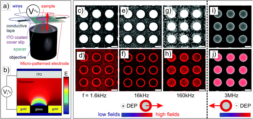 |
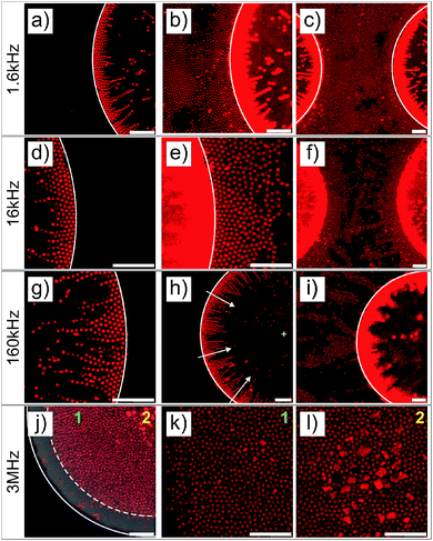
| | Fig. 1 (a) Schematic representation of the experimental setup. (b) Heterogeneous field created between the micro-patterned gold electrode and the non-patterned ITO electrode. (c–j) CLSM experiments performed on a 1 wt% dispersion of spherical core–shell microgels sandwiched between a micro-patterned gold electrode (bottom) and a conductive ITO coverslip (120 μm spacer) (top panels: transmission micrographs (c, e, g and i), bottom panels: fluorescence micrographs (d, f, h and j)). The samples were subjected to an alternating electric field (E = 83 V mm−1) with different frequencies (c and d: 1.6 kHz; e and f: 16 kHz; g and h: 160 kHz; i and j: 3 MHz) during ≈10 min before imaging. At f ≤ 160 kHz, particles experienced a positive DEP and diffuse to high field regions, whereas at f = 3 MHz, they diffused to low field regions driven by a negative DEP. Scale bars: 75 μm. | |
3 Theoretical background
Let us consider a dielectric charged sphere of radius R suspended in a dielectric medium subjected to an alternating electric field E with an angular frequency ω = 2πf (with f referring to the frequency of the applied field). An effective dipole moment is created by the dielectric polarization of the interface of a particle with an associated relaxation time generally referred to as the Maxwell–Wagner relaxation frequency. The net electric dipole moment is then given by28,50| | ![[small mu, Greek, vector]](https://www.rsc.org/images/entities/i_char_e0e9.gif) (ω) = 4πεmfCM(ω)R3 (ω) = 4πεmfCM(ω)R3![[E with combining right harpoon above (vector)]](https://www.rsc.org/images/entities/i_char_0045_20d1.gif) = α = α | (1) |
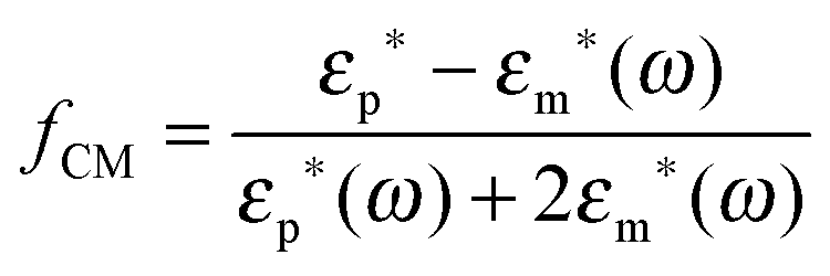
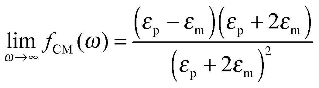
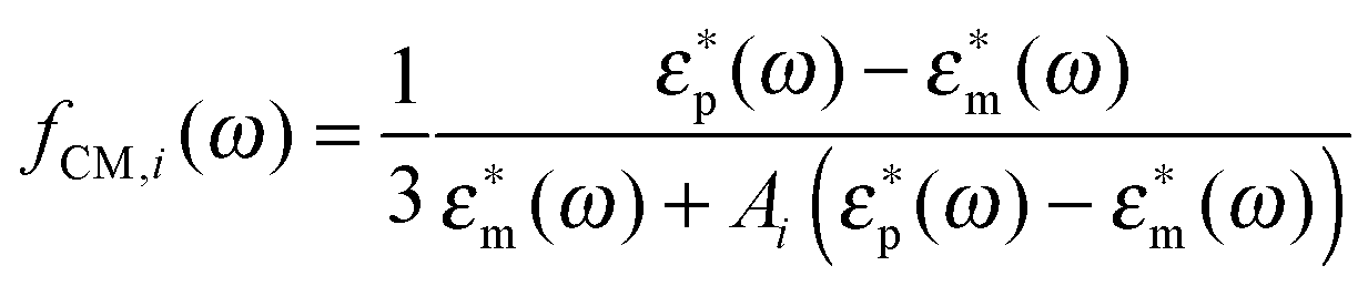
where α(ω) is referred to as the polarizability of the particle, and fCM(ω) is the the Clausius–Mossotti factor defined as| | 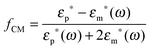 | (2) |
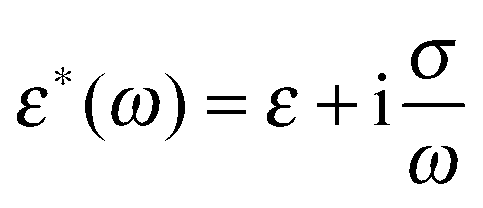
with ε*(ω) being the effective complex permittivity of the particle and medium as indicated by the subscripts p and m, respectively. Its dependence on the angular frequency ω of the applied field is given by| |  | (3) |
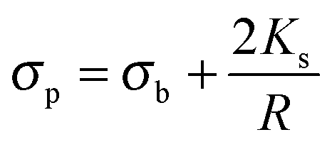
where ε is the permittivity and σ the conductivity. Following the approach proposed by O'Konski,51 the conductivity σp of a particle is given by the sum of the particle's bulk conductivity σb and the surface conductivity 2Ks/R:34,51–53| |  | (4) |
Considering the simple case of polystyrene particles, one can neglect the bulk conductivity and only consider the surface component and use a value for Ks of the order of 1.2 nS.54
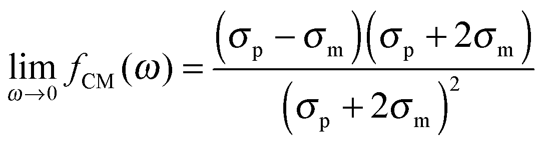
The polarizability of the particles as specified by ℜ(fCM(ω)) in eqn (2) is dominated by the difference in conductivity at low frequencies and by the difference in permittivity at high frequencies between particles and dispersing medium, that is
| |  | (5) |
| | 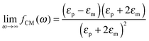 | (6) |
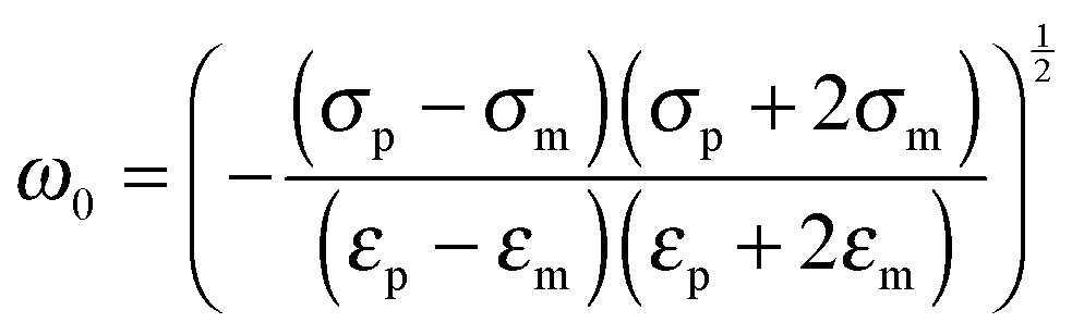
The angular frequency
ω0 for which ℜ(
fCM(
ω)) is equal to zero (
i.e. the frequency where a switch from positive to negative DEP occurs) is given by
| |  | (7) |
The dielectrophoretic (DEP) force generated when the suspended particles experience a non-uniform electric field is equal to
| | | FDEP = 2πεmℜ(fCM(ω))R3∇E2 | (8) |
A so-called positive DEP is observed when particles are more polarizable than the suspending medium, resulting in an attraction towards regions of higher electric field strengths. Likewise, a negative DEP occurs for particles that are less polarizable than the suspending medium, leading to forces that drive the particles towards regions of lower electric field strengths. Both negative and positive DEP can be observed in different frequency regimes for particles with a lower dielectric permittivity and a higher conductivity than the suspension medium (
σp >
σm;
εp <
εm). This is illustrated by calculating the Clausius–Mossotti factor for a 500 nm radius polystyrene particle (
σp = 4.8 × 10
−3 S m
−1,
cf.eqn (4),
εp = 2.55) dispersed in deionized water at 25 °C (
σm = 10
−5 S m
−1,
εm = 78.5) (see Fig. S1a in the ESI
†). At low
ω, the particle experiences a positive DEP dominated by the difference in conductivity, whereas at higher
ω a negative DEP arises from the difference in dielectric permittivities between the particle and the suspending medium. The transition between positive and negative DEP is then expected at a frequency of about 800 kHz.
For prolate particles with a major semi-axis a and a minor semi-axis b, the polarizability depends on the relative orientation of the particles with the electric field. The polarizabilities along the major axes can be written as28,50,55
| | | αi(ω) = 4πεmℜ(fCM(ω))ia2b | (9) |
where, for a prolate particle,
i =
x refers to the major axis, and
i =
y and
z refer to the minor axis). The Clausius–Mossotti factor for each main axis reads
| |  | (10) |
where the depolarization factors
Ai for a prolate particle are equal to
| |  | (11) |
with
e = (1 −
ρ−2)
1/2; defining the eccentricity of the particle (with
ρ =
a/
b being the aspect ratio).
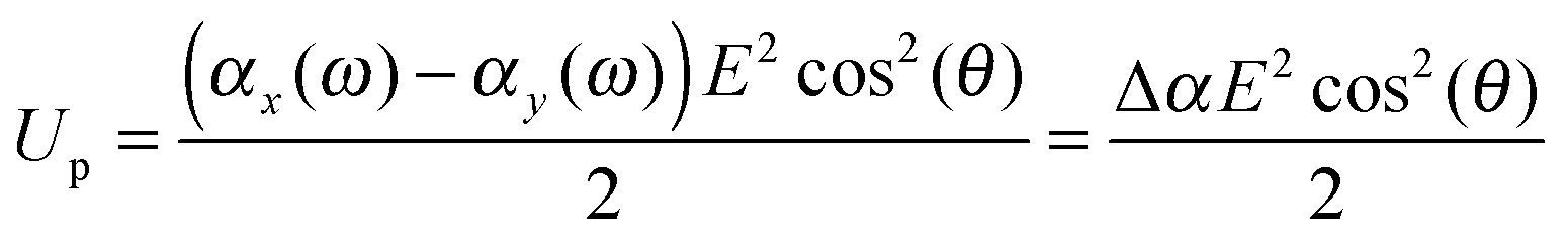
When the particle attains an orientation with an angle θ between the external field and it's major axis, the corresponding potential energy of orientation is equal to
| |  | (13) |
An ellipsoidal particle will therefore align when Δ
αE2 ≈ 2
kBT.
56 Finally, the DEP factor can be described using the average of the real part of
fCM for the three possible directions,
28,55| | | FDEP = 2πεmℜ(fCM(ω))ab2∇E2 | (14) |
with
| |  | (15) |
As an example, the real part of the Clausius–Mossotti factor was calculated for ellipsoidal particles having the same dielectric properties as of a 500 nm polystyrene sphere (
σp = 4.8 × 10
−3 S m
−1,
εp = 2.55) (see Fig. S1b in the ESI
†) with the aspect ratio
ρ varying from 1.1 to 8. For particles with equal volume, these calculations illustrate the enhanced polarizability of anisotropic particles at low frequencies (
f ≲ 10
5 kHz) and a relative decrease at intermediate frequencies (10
5 ≲
f ≲ 8.10
5). It is interesting to note that the transition from positive to negative DEP characterized by
ω0 is almost independent of
ρ, similar to the dielectric properties at higher frequencies. The critical frequency
ω0 is only sensitive to the difference in conductivities of the particles and the suspension medium, and is shifted to higher frequencies with the increase in the difference in conductivities, as shown from the calculation of
fCM for ellipsoidal polystyrene particles (
ρ = 3) presenting different surface conductivities in deionized water (see Fig. S1c in the ESI
†).
4 Results and discussion
4.1 Spherical composite microgels
The first experiments were performed with deionized spherical composite microgel dispersions (1 wt%) using a gold electrode with a 40 nm metal coating patterned with square arrays of 100 μm diameter round voids with a 160 μm pitch. This electrode design allows the generation of a heterogeneous field as confirmed by finite element calculations (see Fig. 1b and Fig. S2 in the ESI†), where the field is stronger at the gold coating and lower within voids, with a large field gradient at the gold/void interface where strong DEP forces are expected.
The particles were imaged in the vicinity of the gold electrode after the application of the field (E = 83 V mm−1) at different frequencies and a high magnification (see Fig. 2). For all frequencies, the particles were highly responsive and rapidly reorganized at the electrode (see DSA at 160 kHz in Video S1 in the ESI†). This process was reversible at all frequencies and turning off the field led to the rapid redispersion/disassembly of the system in less than 5 min (see redispersion of the structure formed at 160 kHz in Video S2 in the ESI†). At low frequencies (f ≤ 160 kHz), the composite microgels experienced a positive DEP and localized over the electrode and at the interface between the gold electrode and the voids where the field gradient was significant (see Fig. 1c–h). At a frequency of 1.6 kHz, the electrode was almost fully covered by the particles. At frequencies of 16 and 160 kHz, less particles were observed at the gold electrode where they built up a more diffuse network indicating that the structure formed was extended to the bulk in 3 dimensions. However, at a higher frequency of 3 MHz (see Fig. 1i and j), particles were found to be concentrated within the voids, i.e., the low field regions driven by a negative DEP. This transition appeared to occur around a frequency of 1.6 MHz, at which the particles started to diffuse to the center of the voids.
 |
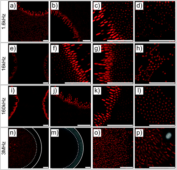
| | Fig. 2 Higher magnification CLSM imaging of the directed self-assembly of a 1 wt% dispersion of spherical core–shell microgels taking place at the micro-patterned electrode observed at a field strength of E = 83 V mm−1 and different frequencies. Solid lines indicate the boundaries between the gold coated and uncoated areas. Different contrasts/intensities were applied to locally illustrate the assembly in the void regions or at the electrodes. At f ≤ 160 kHz (a–i), particles were found to strongly localize in the high field gradient regions, where they built up dipolar chains pointing towards the center of the voids as evidenced by the arrows in (h). The high coverage of the gold surface by the particles and their self-assembly into hexagonal domains at the gold surface and at the gold/void interface at 1.6 kHz are shown in (a)–(c). At 16 kHz, less particles were observed at the gold surface and hexagonal arrays were only seen in the vicinity of the voids in (d)–(f). The number of particles at the gold surface decreased further at 160 kHz and the particles localized at the interface mostly on the void side, where the field gradient was the highest. At 3 MHz, the particles concentrated towards the low field regions driven by negative dielectrophoresis as shown by the dashed lines marking the front line of the dispersion observed from the superposition of the micrographs recorded in transmission and fluorescence modes in (j). Regions 1 and 2, shown in (j), are magnified in (k) and (l), respectively. Scale bars: 10 μm. | |
3D reconstruction of the self-assembly at the micro-patterned electrodes using a 40× dry objective was performed to support our observations (see Fig. S3 in the ESI†). The thick gold coating (40 nm) only allowed the visualization of the particles within the voids. These analyses confirmed the strong localization at the edge of the voids and at the gold electrode at low frequencies and the diffusion of the particles to the interior of the voids at higher frequencies. Interestingly, dipolar particle strings could be observed within the voids when approaching the ITO electrode at 160 kHz (see Fig. S3b, ESI†). These structures are usually observed in a homogeneous field, and therefore illustrate that gradients in the electric field become less pronounced on approach of the uniform ITO electrode.
The structural reorganization of the particles at the micro-patterned electrode was investigated using a 100× oil objective, as summarized in Fig. 2. Hereby, individual particles could be resolved to follow their localized DSA as a function of the frequency at a specific field strength (E = 83 V mm−1). The thick gold coating employed in these experiments did not allow us to clearly evidence both the particles present in the void and at the electrode. Therefore, the contrast was adjusted to visualize the particles at different locations in the rows of images given in Fig. 2. For instance, Fig. 2a and b present the same micrograph with different contrasts for visualizing different parts of the sample. At f ≤ 160 kHz, particles were closely packed in crystalline arrays in high field gradient regions that extended over 2 to 3 layers and formed short dipolar chains pointing to the centre of the voids (Fig. 2a–i). At 1.6 kHz, the composite microgels strongly localized at the surface of the gold electrode where they built blocks of 2D hexagonally packed crystals (Fig. 2b and c); increasing the frequency caused less particles to be observed at the electrodes where the particles started to form dipolar aggregates that extended to the bulk (see Fig. 2e, f and i). In this frequency regime, it is important to note that all assemblies were dynamic as a consequence of the heterogeneous field application giving rise to an apparent flow that was particularly pronounced at 160 kHz frequency. At 3 MHz, the particles were repelled from the high field gradient regions and were found to mostly diffuse to the low field regions within the voids. This was clearly visible from the displacement of the front line of the assembly which was about 7.5 μm away from the edge of the electrode (see Fig. 2j). In the dense region, the particles were strongly interacting without, however, any clear indication of strong directional dipolar interactions. The use of negative DEP to locally concentrate and crystallize dispersions is well-known as shown in other studies.39–42 In our experiments, however, the particles did not crystallize in the voids at the applied field strength. Aggregates and larger particles were found to concentrate at the centre of the voids as they experienced, due to their larger volume, stronger DEP forces. This illustrates the possibility to hierarchically organize the particles in the low field regions at high frequencies and one of the basic principles of the use of DEP forces to selectively sort out or isolate particles as a function of their polarizability.
The polarization mechanism discussed in the theory describes the so-called δ dispersion defined by the Maxwell–Wagner–O'Konski (MWO) relaxation. It assumes that the polarizability is frequency dependent, whereas the permittivity and conductivity of the particles and medium are frequency independent. This model captured the frequency dependent localization of the particles towards either the high field regions at low frequencies (positive DEP) or the low field regions at high frequencies (negative DEP). This transition observed in our experiments around 1.6 MHz is characteristic of charged particles dispersed in low dielectric media with a higher refractive index (see Fig. S1a, ESI†).28,31,33,34,50 Different cases were investigated for which the Clausius–Mossotti factors were calculated (see Fig. S4 in the ESI†). First, a polystyrene sphere with the same radius of 267 nm as the core of the core–shell particles was considered (εp = 2.55, σs = 8.99 mS m−1, cf.eqn (4)). Then, a PNIPAM microgel was considered, using the value found in recent dielectric spectroscopy obtained at 20 °C for a swollen microgel particle with a radius of about 200 nm prepared by precipitation polymerization (εp ≈ 75 and σp ≈ 2.7 × 10⁻³ S m−1).57 Finally, a core–shell model was employed for the composite microgels using a 267 nm radius polystyrene core surrounded by a 269 nm fuzzy PNIPAM shell. This theoretical approach, initially developed to describe the dielectrophoresis of cells,31,50,58 relies on a concentric multi-shell model that can be easily implemented for single-shelled particles (see eqn (S1) in the ESI†). Core–shell particles were expected to present two intrinsic relaxation frequencies corresponding to the two components constituting the system. The transitions from positive to negative DEP were calculated to be at f = 1.43, 1.36 and 1.39 MHz for the core, microgel and core–shell particles, respectively. Both core and microgel particles were found to present a transition at similar ω0 values. Therefore, it was not really surprising to find a similar transition for the core–shell particles. The calculated ω0 value for core–shell particles was in good agreement with our experimental observations. These calculations are strongly dependent on the volume of the two components. Therefore, the polarizability of the composite microgels is expected to be mostly determined by the shell properties. However, a more pronounced response at high frequencies is expected for composite microgels as compared to pure microgels due to the presence of the polystyrene core.
Other polarization mechanisms occur for ω < ω0, related to the modification of the double layer structure following two mechanisms.29,30,59 The first polarization mechanism is related to the accumulation of ions on either side of the impenetrable particle core as a result of ion fluxes induced by the electric field. For very low surface charge densities the resulting dipole is opposite to the electric field direction, while for larger surface charge densities the induced dipole points in the same direction as the external electric field. This polarization mechanism is commonly referred to as “concentration polarization”, “α-relaxation”, or “volume diffusion”. Relaxation of the thus induced dipole moment requires ions to diffuse from one side of the core to the other side, which corresponds to a distance πR (with R being the typical linear dimension of the particle). The time required to diffuse over that distance is (πR)2/D (where D is the ion-diffusion coefficient). The respective characteristic frequency f = ω/2π is thus of the order f ≈ 2D/(πR)2. The second double-layer polarization mechanism is simply the electric-field induced distortion of the charge distribution within the double layer, other than that caused by concentration polarization. The ions are now locally, on each side of the colloid, displaced over distances comparable to the Debye length. The corresponding relaxation frequency for this “ion-migration relaxation process” is thus of the order, f ≈ 2Dκ2, with κ being the inverse Debye length. As our experiments are performed in deionized water (where we consider κ−1 ≈ 100 nm), the predominant free charges are the protons (for which D = 10−8 m2 s−1). Using the hydrodynamic radius of the particles (R = 536 nm), the two above described polarization mechanisms are thus found to occur at frequencies lower than approximately 7 kHz for the α-relaxation process and about 2 MHz for the ion-migration process. We do not observe any change in the response of our system at these frequencies, which is attributed to the small amplitudes of the dipoles induced by these polarization mechanisms, as the zeta potential of −33 mV of our particles is quite low and the double-layer thickness is large.
At lower frequencies, the self-assembly at the electrode is affected by electrode polarization. For perfectly polarizable electrodes separated by a distance 2h, largely greater than the Debye length, κ−1, electrode polarization becomes significant for frequencies f ≲ 10D/(4πκ−1h),15 where κ−1 ≈ 100 nm under deionized conditions, as described in more detail in the ESI† (Section 5, electrode polarization). In our experiments, such contributions are thus expected to come into play for frequencies less than about 1.4 kHz for 2h = 120 μm. When particles diffuse to the electrode charge polarization layer, it generates a distortion of the local field by the particles that is at the origin of an electrohydrodynamic (EHD) flow observed by Saville et al.60 This effect is at the origin of the 2D crystal formation60–63 and due to more complex self-assembly phenomena in the electrode vicinity when the polarization layer is large compared to the size of the particles.63 We refer to these studies and in particular to the work of Ristenpart et al.64 for a more detailed description of this phenomenon. The strong localization of the composite microgels at the electrode particularly pronounced at 1.6 kHz was therefore attributed to electrode polarization driving the particles to the electrode, where they further self-assemble through a combination of dipolar interactions, EHD flow and DEP forces stemming from the local field gradient generated by the patterned electrodes.
4.2 Ellipsoidal composite microgels
Similar experiments were performed on ellipsoidal composite microgel dispersions (1 wt%). The particles were first imaged using a CLSM either in the vicinity of the micro-patterned gold electrode or close to the ITO electrode, as schematically illustrated in Fig. 3a and a′ using a low magnification 10× dry objective in fluorescence and transmission modes. From our observations at the micro-patterned electrode, ellipsoidal core–shell microgels were found to respond similar to spherical particles with a positive DEP at f ≤ 160 kHz (Fig. 3b–d, f–h and b′–d′, f′–h′) and a negative DEP at 3 MHz (Fig. 3e, i and e′, i′). This was to be expected as the ellipsoidal particles are the products of an almost isochore transformation of the spherical particles. The total surface charge density is then expected to decrease in the order of 20% at ρ = 3.3 from the ratio of surfaces between isochore spherical and prolate ellipsoidal particles. Such a decrease of σp should not significantly affect the transition, as shown in Fig. S1b and c (ESI†). At f = 1.6 kHz, fluorescence and transmission micrographs indicated the dense coverage of the gold pattern by the particles (see Fig. 3b and f) and their homogeneous adsorption at the opposite ITO electrode (see Fig. 3b′ and f′) caused by the strong electrode polarization. With the increase of f to 16 kHz and 160 kHz, the DSA at the ITO electrode became sensitive to the complex field generated by the micro-patterned electrode and therefore to dielectrophoretic forces (see Fig. 3c′, g′ and d′, h′). Obtaining an assembly at the ITO electrode similar to the micro-patterned electrode was particularly clear at 16 kHz, whereas at 160 kHz the particles appeared to be less segregated at the ITO electrode. This was interpreted as a consequence of the lower particle polarizability and of the decreasing range of DEP forces at higher frequencies. Finally at f = 3 MHz, particles were observed all over the ITO electrode with a concentration gradient towards the low field regions (see Fig. 3e′ and i′).
 |
| | Fig. 3 CLSM experiments performed on a 1 wt% deionized dispersion of ellipsoidal core–shell microgels sandwiched between a micro-patterned gold electrode and a conductive ITO coverslip with the micro-patterned electrode on top (a) or at the bottom (a′). (b–i) Imaging in the vicinity of the micro-patterned electrode after application of the electric field (E = 83 V mm−1) for about 10 min at different frequencies by fluorescence (top panels) and transmission (bottom panels) CLSM imaging (b and f: 1.6 kHz; c and g: 16 kHz; d and h: 160 kHz; e and i: 3 MHz). (b′–i′) Same experiments performed by placing the ITO at the bottom. Scale bars: 75 μm. | |
The structures observed under the field are fully reversible and can be redispersed within 5 min after field cessation. The redispersion process observed by monitoring the excess fluorescence observed at the ITO electrode is summarized in Fig. S5 in the ESI.† This allowed us to confirm the initial localization of the high concentration regions observed at f = 1.6 kHz, 16 kHz and 1.6 MHz. Hereby, the redispersion was driven by the diffusion of the particles to the depleted regions, where approaching particle “clouds” created defined interfaces before they finally mixed up. This process led to square patterns at 1.6 kHz and 1.6 MHz and to a more intricate pattern at 16 kHz within the first 2 minutes. Besides demonstrating that our design could be employed to manipulate in situ dispersions and investigate complex diffusive mixing processes, these experiments clearly showed the degree of localization in different frequency ranges. For instance the particles were strongly localized within the voids in the low field regions at f = 3 MHz at the patterned electrode as shown from their redispersion process (see the transmission and fluorescence CLSM micrographs in Fig. S6, ESI†, 3rd and 4th rows).
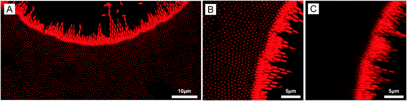
The DSA of the core–shell ellipsoidal microgels was further investigated at higher magnifications either at the micro-patterned gold electrode (see Fig. 4) or at the ITO electrode (see Fig. S6 in the ESI†). These particles were studied in detail in a former study with respect to their ability to align and self-assemble under “homogeneous” alternating fields.22 Therefore, the use of these ellipsoidal particles allowed us to not only probe their localization and organization at the electrode but also to obtain insights into their local alignment with the field. At f ≤ 160 kHz, similar to spheres, ellipsoidal particles preferentially self-assembled at the gold surface and densely rearranged at the interface between the gold electrode and the voids under the influence of positive DEP and dipolar forces. In this frequency regime, the particles assembled over the gold coating were aligned with their long axis perpendicular to the electrode and densely packed at the edge of the voids, which at 160 kHz (see Fig. 4i–k) results in the formation of small hexagonal arrays. Further away from the edge atop the gold electrode, disordered dipolar aggregates coexisting with strings were observed. However, ellipsoids within the voids at the edge of the electrode built short dipolar pyramidal structures and chains pointing towards the centre of the voids (see Fig. 4a–c, e–g and i–k). A transition from a parallel to a perpendicular orientation with respect to the imaging plane was evidenced from the variation of the imaged particle cross-sections. Hereby, anisotropic particles aligned parallel to the imaging plane appeared as ellipses with an aspect ratio close to 3, whereas the perpendicular orientation was characterized by a circular cross-section. The continuous change in aspect ratio of the imaged elliptic cross-section from 3 to 1 in the high field gradient regions demonstrated the high sensitivity of the particles to the local field. Conversely, at 3 MHz, the particles were concentrated mostly within the voids in the low field regions. Similar to the spherical particle dispersion, the front line of the dispersions was observed at a distance of about 7.5 μm from the gold/void interface by comparing the fluorescence and transmission micrographs (Fig. 4m and n, respectively). Moreover, the particles were found to partially align towards the center of the voids (see Fig. 4o and p) as evidenced from the time-averaged Fourier transformation presenting an anisotropic pattern shown in the inset of Fig. 4p.
 |
| | Fig. 4 Higher magnifications CLSM imaging of the dynamic self-assembly of the ellipsoidal core–shell microgels (1 wt% deionized dispersion) over the micro-patterned electrode coated with a thin layer of gold at different frequencies (a–d: 1.6 kHz; e–h: 16 kHz; i–l: 160 kHz, m–p: 3 MHz) at a field strength E = 83 V mm−1. At a frequency of f ≤ 160 kHz the particles orientated and self-assembled at the electrode and at the interface along the local field direction building up dynamical dipolar networks at the electrode (a–l, shown in detail in d, h and l), small hexagonal arrays approaching the voids at 160 kHz (i–k) and short pyramidal dipolar assemblies from the interface towards the center of the voids (a–c, e–g and i–k). At 3 MHz frequency, similar to spheres, the particles concentrated within the voids as shown by fluorescence (n) and transmission (m) CLSM imaging with a depleted region between the end of the coated area (solid lines) and the end-of-assembly (dashed lines). Here, particles within the voids partially aligned along the local field direction (m and p) demonstrated by the time averaged Fourier transformation of the image taken in (p) (see inset). | |
The detailed examination of the colloidal assembly at the ITO electrode in Fig. S7 in the ESI† confirmed the results obtained at lower magnifications and the homogeneous covering of the electrode at 1.6 kHz, where the particles formed vertically aligned 2D sheets (see Fig. S7a–d in the ESI†). This assembly was sufficiently stable and could be accurately imaged in the xz plane. The height of such a structure could not be measured due the high refractive mismatch that prevented the examination deep in the bulk. However, the assembly did not span the full gap as it was not observed on the facing micro-patterned electrode. Fig. S7d (ESI†) shows the periodic organization in a 2D crystal belonging to the C2mm plane group with an average centre-to-centre angle determined as 18 ± 2 °C in good agreement with the observations of Singh et al. on dipolar polystyrene ellipsoids with an aspect ratio of 3.20 Self-assembly into 2D sheets is predicted for this aspect ratio from recent simulations assuming a two-point charge model that captures the dipolar character of conductive ellipsoids.22 However, when polarized in an alternating AC field the particles were found to rearrange into a defined tubular structure spanning the two electrodes at a similar number density.22 This was interpreted as an energy minimization of the 2D sheet assembly and was found to depend on the size of the system (i.e. the number of particles in x and z directions). The persistent organization into 2D sheets was therefore attributed to the limited extension in the z-direction. At 16 and 160 kHz, disordered dipolar aggregates were observed in the areas facing the gold electrode coexisting with single particle strings, whereas in the regions opposite to the voids less particles were detected. At 3 MHz, no sign of clear localization was observed and only single diffusing particles aligned along the field were detected in majority. The assembly on the non-patterned electrode was therefore found to also strongly depend on the frequency. To summarize our observations at the ITO electrode at a constant field strength and different frequencies, low frequencies were dominated by the mass transport towards the electrode, where the particles self-assembled irrespective of the complex field generated by the micro-patterned electrode. Intermediate frequencies (16 and 160 kHz) were characterized by concentration and self-assembly of the particles in the high field regions facing the gold pattern, whereas at high frequencies the particles align only along the field.
These results demonstrate the strong potential of our DSA strategy for printing applications as it was possible at certain frequencies to transfer the structure from the micro-patterned to the non-patterned electrode. Our experiments also suggested that defined vertically aligned arrays could be generated around the voids, which was confirmed by investigating the DSA at the micro-patterned electrode of a more concentrated dispersion (5 wt%) at f = 16 kHz (see Fig. 5). Larger 2D arrays were observed to form around the voids through the combination of EHD flow, DEP forces and dipolar interactions (Fig. 5A and B). The crystalline order was observed on a single layer as shown from the 3D projection in Fig. 5C. The average center-to-center distance, d, within hexagonal arrays was determined as 0.88 μm, much larger than the full short axis, 2b = 0.542 μm, confirming the overall repulsive character of the lateral dipolar interactions.
 |
| | Fig. 5 (A and B) 2D CLSM micrographs of the organization of a more concentrated ellipsoidal core–shell microgel dispersion (5 wt%) at the micro-patterned electrode coated with a thin layer of gold at a field strength E = 83 V mm−1 using a frequency of 16 kHz highlighting the local reorganization in hexagonal arrays. (C) 3D projection of the assembly at the gold interface (25.83 × 25.83 × 4.93 μm3). | |
4.3 Binary spherical microgel mixture
Besides the fundamental understanding of complex fields and their influence on particles assembly, one of the overarching goals in this study was to build complex and novel nanostructured materials with pre-programmed microstructures. To do so, the responsive nature of the particles was employed to locally control the directed self-assembly into binary mixtures. A binary mixture consisting of core–shell microgels (1.04 wt%, with the polystyrene core labeled in green and the PNIPMAM shell labeled in red) and an excess of pure PNIPAM microgels (6.86 wt%, labeled in red) was investigated. The choice of these two components relied on the specific difference in their polarizability and thermoresponsiveness dictated by their respective chemical composition, size and charge. The ionic strength was set to 10−4 mol L−1 by adding a small amount of potassium chloride to the mixture in order to slightly decrease the range of the electrostatic interactions. Temperature was employed as a control parameter to adjust the overall effective volume fraction of the microgel particles, which is known from former studies to drive concentrated dispersions into fluid, crystalline and glassy states.65,66 The high magnification CLSM fluorescence micrographs of the binary mixture are presented in Fig. 6 and observations made at lower magnifications are summarized in Fig. 7. At 20 °C, the core–shell particles were homogeneously dispersed within microgel particles densely packed into crystals (see Fig. 6a–c). The dispersion appeared to be arrested, which was supported by 2D tracking of the larger core–shell particles. The particle trajectories in the xy plane were sampled over 30 s and are summarized in Fig. S7a (ESI†). The computed 2D mean square displacement, 〈Δr2(t)〉, was found to be constant at a plateau value δ2 = 10−3 μm2 (see Fig. S7c, ESI†). When compared to the hydrodynamic radius of the core–shell particles (RH = 536 nm), the ratio δ2/(2RH)2 = 8.7 × 10⁻⁴ confirmed that the particles were fully arrested and only rattled to a distance of the order of 3% of their diameter. This was supported by the average distance between 2 microgel particles in a 2D crystalline hexagonal lattice, d, determined at 431 nm, significantly lower than the hydrodynamic microgel diameter (2RH = 490 nm), attesting for the dense packing of microgel in the crystals.
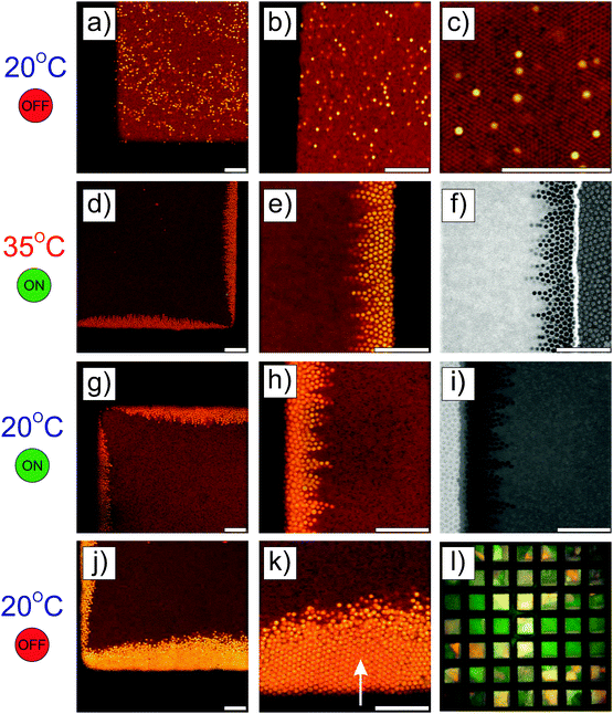 |
| | Fig. 6 High magnification CLSM micrographs of a binary mixture of core–shell microgels (1.04 wt%, green and red) dispersed in an excess of pure fluorescent PNIPAM microgels (6.86 wt%, red) recorded at a square-mesh micro-patterned gold electrode (40 nm gold coating). (a–c) Imaging of the dispersion at 20 °C showing the homogeneous dispersion of the core–shell microgels within pure microgels in a crystalline state. (d–f) Micrographs taken at 35 °C in the fluid state and selective DSA of the core–shell microgels at the interface after application of the field (E = 83 V mm−1, f = 160 kHz). The organization of the particles at the gold electrode is shown from the processed micrograph in (f). (g–i) Recrystallization of the microgels by slow cool-down under the field to 20 °C after 1 h equilibration. (j and k) CLSM fluorescence micrographs of the frozen DSA about 30 min after field cessation. The slight drift of the assembly, indicated by the arrow, evidenced the crystalline ordering of the larger particles in (k). The crystalline order of the microgels was confirmed by the presence of Bragg reflections observed using polarized microscopy in (l). | |
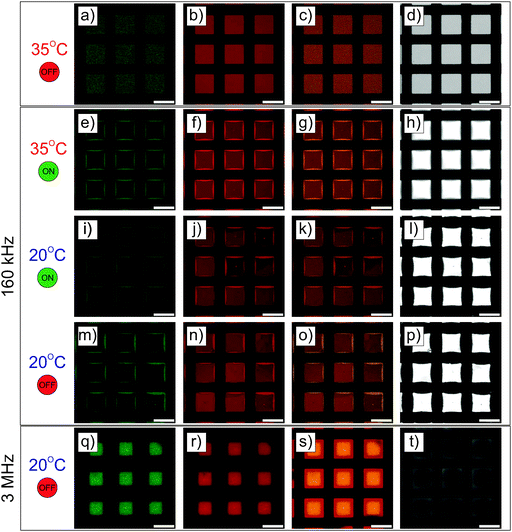 |
| | Fig. 7 CLSM micrographs of the hierarchical DSA at lower magnification near the micro-patterned electrode presenting the green channel (core–shell particles, 1st column), the red channel (core–shell and pure microgels, 2nd column), the superposition of both fluorescence channels (3rd column) and the micrographs recorded in transmission mode (4th column). The dispersion was imaged at 35 °C before (a–d) and after (e–h) the application of the field (E = 83 V mm−1, f = 160 kHz). Maintaining the field the dispersion was then imaged after cooling down to 20 °C (i–l) and finally after field removal at 20 °C (m–p). The same procedure was repeated at a frequency of 3 MHz, for which the resulting structure is imaged in (q)–(t). | |
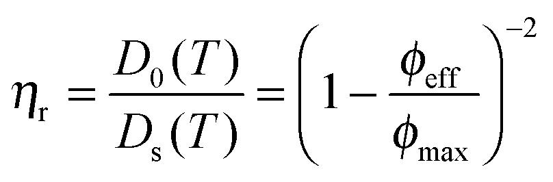
Upon increasing the temperature to 35 °C, the crystalline order disappeared and the particles became diffusive after 1 h equilibration as shown from their trajectories (see Fig. S4b, ESI†). No phase separation was observed and the core–shell particles remained homogeneously distributed within the whole sample as confirmed from the CLSM micrographs in Fig. 7a–d. The computed 2D 〈Δr2(t)〉 was found to increase linearly with time and could be used to determine the self-diffusion of the core–shell particles, Ds, using the linear relation 〈Δr2(t)〉 = 4Dst. Ds was derived as 3.2 × 10⁻² μm2 s−1, which was about 20 times lower than the diffusion of the dilute core–shell particles, D0 = 6.6 × 10⁻¹ μm2 s−1, determined by DLS at 35 °C. The corresponding effective volume fraction of the dispersion, ϕeff, was then estimated using the Quemada's equation67 by assuming that the ratio D0(T)/Ds(T) was proportional to the relative zero shear viscosity, ηr as follows:
| |  | (16) |
where
ϕmax refers to the maximal effective volume fraction, which we defined by the hard sphere glass transition at 0.58. Under such assumptions,
ϕeff was found to be 0.45. The increased mobility of the particles in their fluid state allowed us to selectively assemble the core–shell particles by applying the field (
E = 83 V mm
−1,
f = 160 kHz) (see
Fig. 6(d)–(f) and 7(e)–(h)). The core–shell particles were then found to strongly localize at the gold/void interface as shown from the superposition of the green and red fluorescence channels and the transmission micrographs in
Fig. 7g and h, respectively. There, the core–shell particles built-up dipolar pyramid-like assemblies presenting a local hexagonal ordering ended by short dipolar chains (
Fig. 6(d)–(f)). The dense packing slightly extended to the gold as evidenced from
Fig. 6f where the contrast has been artificially enhanced on both sides of the interface. However, the local hexagonal order was not found on more than 2 layers and was mostly 2D. Keeping the field on, the dispersion was slowly cooled back to 20 °C (within 30 min) and equilibrated for an extra hour. At this temperature, the association was maintained as shown in
Fig. 7i–k and the pure microgels recrystallized as evidenced in
Fig. 6(g)–(i). This was also confirmed by the increase of the transmission visible in
Fig. 7l. About 30 min after the field was turned off, the assembly was almost integrally preserved (see
Fig. 7m–p) with the exception of the interface between the two particles, which became less sharp as the two kinds of particles partially mixed up and led to a slight drift of the hierarchical assembly (see
Fig. 7(j) and (k)). The drift, indicated by the arrow in
Fig. 6k, was taken at our advantage to clearly visualize the crystalline ordering of the larger particles that could be imaged over 5 layers.The promoted crystalline order of the core–shell particles with respect to experiments performed at 35 °C with field, which we ascribed to the additional confinement generated by the expansion of the microgel particles and the slow increase of the volume fraction during the cool-down process was worth noting. It indicates that dense microgels could be employed not only to maintain the assembly of different components but also to promote the ordering of the particles during the hierarchical DSA by local confinement. Finally, the presence of Bragg reflections stemming from the pure microgel crystallization was confirmed by polarized microscopy in
Fig. 6l.
The full process was repeated at a frequency of 3 MHz and the resulting DSA observed at 20 °C in the absence of field is presented in Fig. 7q–t. Driven by negative DEP, the core–shell particles were found to be concentrated at the centre of the voids as confirmed by the imaging in fluorescence and transmission modes. However, in analogy to the one-component core–shell microgel dispersions the core–shell particles were not found to present any crystalline ordering at the applied field strength and frequency. These experiments further demonstrated that complex binary mixtures can be rewritten (even to another structure, i.e. by using another frequency) in 3D by combining field-localized DSA with the thermoresponsive properties of PNIPAM and PNIPMAM microgel based particles.
5 Perspectives and outlook
To summarize our results, a complex heterogeneous alternating field generated by the superposition of a micro-patterned gold electrode and a non-patterned ITO electrode allowed for precise manipulation of colloidal particles in dispersions. Composite microgel particles were employed to demonstrate this concept. Varying the frequency enabled to reversibly control the resulting structure at the electrode following the dielectric properties of the particles and medium. Such manipulation is fundamentally interesting as it enables us to trap particles within the non-conducting voids at high frequency and to study, for instance, their phase diagram as a function of the field strength as shown in other studies.39–42 The same principle can apply for the structure formation at the electrode interface, for which a more detailed modeling is necessary to account for contributions other than dielectrophoretic forces. In terms of applications, our method could be employed for printing as some of the structures (i.e. at 16 kHz) could be transferred from the micro-patterned electrode to the non-patterned electrode.
The extension to ellipsoidal-shaped colloids has shown that not only the localization but also the orientation were affected by the local field. In our experiments, 2D hexagonally packed arrays of ellipsoidal particles standing at the surface of the gold electrode were generated. Our results are promising with the perspective of the development of photovoltaic materials based on semi-conducting nanowire arrays. Hereby, the proposed complex field based multiscale self-assembly approach could represent an important advance in the cost-efficient and large-scale fabrication of such materials. For example, an array of indium phosphide nanowires (InP NWs) currently hold the world record photoefficiency for such a design.68 However, with the exception of the work of Jamshidi et al.,43 self-assembly routes for cost-efficient fabrication of such arrays using preformed nanowires are, to our knowledge, still missing. In addition, such materials are well-known to strongly adsorb light, limiting their applications.69 Thus, the use of micro-patterned electrodes may find future use to create semi-transparent photovoltaic devices.
Finally, we demonstrated that our approach could be extended to binary thermoresponsive microgel mixtures, thus allowing us to create complex rewritable structures in 3D that can be dynamically maintained through the temperature control of the effective volume fraction of the samples. This can lead to the development of advanced photonic materials as shown in our proof of concept experiments. The extension to multi-component mixtures may be applied to generate novel electronic materials. The next step towards the development of novel advanced materials implies modifications of the surface chemistry of the electrodes and particles to maintain the self-assembly in bulk and at the surface.
Putting our results into perspective, we believe field-localized DSA paves the way towards a nanoscale control of the local field and could become a powerful alternative for designing hybrid materials in three dimensions and allow for a major step in the fabrication of advanced functional materials for tomorrow's needs.
Acknowledgements
J. J. C. acknowledges the Knut and Alice Wallenberg Foundation (project grant KAW 2014.0052) and A. F. D. acknowledges the Swiss National Science Foundation (Ambizione grant PZ00P2_148040) for the financial support. The authors acknowledge Prof. Jan Vermant and Dr. Patrick Pfleiderer for the processing of the ellipsoidal particles. Linda K. Månsson and Jasper Immink are acknowledged for providing the labeled pure microgel particles and Janne-Mieke Meijer for the labeling of the core–shell composite microgels and the particle tracking analysis. Prof. Jan K. G. Dhont is acknowledged for providing useful insights into the polarization mechanism.
References
- Y. Xia, B. Gates and Z. Y. Li, Adv. Mater., 2001, 13, 409 CrossRef CAS.
- A. Yethiraj, J. H. J. Thijssen, A. Wouterse and A. van Blaaderen, Adv. Mater., 2004, 16, 596 CrossRef CAS.
- A. N. Shipway, E. Katz and I. Willner, ChemPhysChem, 2000, 1, 18 CrossRef CAS PubMed.
- A. I. Hochbaum, R. Fan, R. He and P. Yang, Nano Lett., 2005, 5, 457 CrossRef CAS PubMed.
- A. Yethiraj, Soft Matter, 2007, 3, 1099 RSC.
- Y. Min, M. Akbulut, K. Kristiansen, Y. Golan and J. Israelachvili, Nat. Mater., 2008, 7, 527 CrossRef CAS PubMed.
- M. Grzelczak, J. Vermant, E. M. Furst and L. M. Liz-Marzán, ACS Nano, 2010, 4, 3591 CrossRef CAS PubMed.
- B. Bharti and O. D. Velev, Langmuir, 2015, 31, 7897 CrossRef CAS PubMed.
- G. Singh, H. Chan, A. Baskin, E. Gelman, N. Repnin, P. Král and R. Klajn, Science, 2014, 345, 1149 CrossRef CAS PubMed.
- A. Yethiraj and A. van Blaaderen, Nature, 2003, 421, 513 CrossRef CAS PubMed.
- S. Nöjd, P. S. Mohanty, P. Bagheri, A. Yethiraj and P. Schurtenberger, Soft Matter, 2013, 9, 9199–9207 RSC.
- P. S. Mohanty, P. Bagheri, S. Nöjd, A. Yethiraj and P. Schurtenberger, Phys. Rev. X, 2015, 5, 011030 Search PubMed.
- S. Sacanna and D. J. Pine, Curr. Opin. Colloid Interface Sci., 2011, 16, 96 CrossRef CAS.
- S. N. Fejer, D. Chakrabartia and D. J. Wales, Soft Matter, 2011, 7, 3553 RSC.
- K. Kang and J. K. G. Dhont, Soft Matter, 2010, 6, 273 RSC.
- K. Chaudhary, J. J. Juárez, Q. Chen, S. Granick and J. A. Lewis, Soft Matter, 2014, 10, 1320 RSC.
- B. Liu, T. H. Besseling, M. Hermes, A. F. Demirörs, A. Imhof and A. van Blaaderen, Nat. Commun., 2014, 5, 3092 Search PubMed.
- A. Kuijk, T. Troppenz, L. Filion, A. Imhof, R. van Roij, M. Dijkstra and A. van Blaaderen, Soft Matter, 2014, 10, 6249 RSC.
- J. K. G. Dhont and K. Kang, Soft Matter, 2014, 10, 1987 RSC.
- J. P. Singh, P. P. Lele, F. Nettesheim, N. J. Wagner and E. M. Furst, Phys. Rev. E: Stat., Nonlinear, Soft Matter Phys., 2009, 79, 050401 CrossRef PubMed.
- A. A. Shah, H. Kang, K. L. Kohlstedt, K. H. Ahn, S. C. Glotzer, C. W. Monroe and M. J. Solomon, Small, 2012, 8, 1551 CrossRef CAS PubMed.
- J. J. Crassous, A. M. Mihut, E. Wernersson, P. Pfleiderer, J. Vermant, P. Linse and P. Schurtenberger, Nat. Commun., 2014, 5, 5516 CrossRef CAS PubMed.
- S. Sacanna, W. T. M. Irvine, P. M. Chaikin and D. J. Pine, Nature, 2010, 464, 575 CrossRef CAS PubMed.
- C. Zhifeng, L. Fuhua, Z. Zexin and M. Yu-qiang, Soft Matter, 2013, 9, 11392 RSC.
- J. J. Crassous, A. M. Mihut, L. K. Månsson and P. Schurtenberger, Nanoscale, 2015, 7, 15971 RSC.
- M. Kamp, N. A. Elbers, T. Troppenz, A. Imhof, M. Dijkstra, R. van Roij and A. van Blaaderen, Chem. Mater., 2016, 28, 1040 CrossRef CAS.
- A. F. Demirörs, P. P. Pillai, B. Kowalczyk and B. A. Grzybowski, Nature, 2013, 503, 99 CrossRef PubMed.
-
Electromechanics of Particles, ed. T. B. Jones, Cambridge University Press, 1995 Search PubMed.
- C. Zhang, K. Khoshmanesh, A. Mitchell and K. Kalantar-zadeh, Anal. Bioanal. Chem., 2010, 396, 401 CrossRef CAS PubMed.
- C. Zhao and C. Yang, Microfluid. Nanofluid., 2012, 13, 179 CrossRef.
- Y. Huang, R. Holzel, R. Pethig and X.-B. Wang, Phys. Med. Biol., 1992, 37, 1499 CrossRef CAS PubMed.
- R. Pethig, Y. Huang, X.-B. Wang and J. P. H. Burt, J. Phys. D: Appl. Phys., 1992, 24, 881 CrossRef.
- R. Pethig, Crit. Rev. Biotechnol., 1996, 16, 331 CrossRef.
- H. Morgan, M. P. Hughes and N. G. Green, Biophys. J., 1999, 77, 516 CrossRef CAS PubMed.
- A. Nakano and A. Ros, Electrophoresis, 2013, 34, 1085 CrossRef CAS PubMed.
- T. Z. Jubery, S. K. Srivastava and P. Dutta, Electrophoresis, 2014, 35, 691 CrossRef CAS PubMed.
- A. P. Barlett, A. K. Agarwal and A. Yethiraj, Langmuir, 2011, 27, 4313 CrossRef PubMed.
- A. F. Demirörs, D. Courty, R. Libanori and A. R. Studart, Proc. Natl. Acad. Sci. U. S. A., 2016, 113, 4623 CrossRef PubMed.
- M. E. Leunissen, M. T. Sullivan, P. M. Chaikin and A. van Blaaderen, J. Chem. Phys., 2008, 128, 164508 CrossRef PubMed.
- M. E. Leunissen and A. van Blaaderen, J. Chem. Phys., 2008, 128, 164509 CrossRef PubMed.
- J. J. Juárez, P. P. Mathai, J. A. Liddle and M. A. Bevan, Lab Chip, 2012, 12, 4063 RSC.
- T. D. Edwards and M. A. Bevan, Langmuir, 2014, 30, 10793–10803 CrossRef CAS PubMed.
- A. Jamshidi, P. J. Pauzauskie, P. J. Schuck, A. T. Ohta, P.-Y. Chiou, J. Chou, P. Yang and M. C. Wu, Nat. Photonics, 2008, 2, 86 CrossRef PubMed.
- E. M. Freer, O. Grachev, X. Duan, S. Martin and D. P. Stumbo, Nat. Nanotechnol., 2010, 5, 525 CrossRef CAS PubMed.
- B. K. Sarker, S. Shekhar and S. I. Khondaker, ACS Nano, 2011, 5, 6297 CrossRef CAS PubMed.
- J. J. Crassous, H. Dietsch, P. Pfleiderer, V. Malik, A. Diaz, L. A. Hirshi, M. Drechsler and P. Schurtenberger, Soft Matter, 2012, 8, 3538 RSC.
- K. M. Keville, E. I. Franses and J. M. Caruthers, J. Colloid Interface Sci., 1991, 144, 103126 CrossRef.
- C. C. Ho, A. Keller, J. A. Odell and R. H. Ottewill, Colloid Polym. Sci., 1993, 271, 469 CAS.
- L. K. Månsson, J. N. Immink, A. M. Mihut, P. Schurtenberger and J. J. Crassous, Faraday Discuss., 2015, 181, 49 RSC.
-
H. Morgan and N. G. Green, AC electrokinetics: colloids and nanoparticles, Research Studies Press, Philadelphia, PA, USA, 2003 Search PubMed.
- C. T. O'Konski, J. Phys. Chem., 1960, 64, 605 CrossRef.
- W. M. Arnold, H. P. Schwan and U. Zimmermann, J. Phys. Chem., 1987, 91, 5093 CrossRef CAS.
- N. G. Green and H. Morgan, J. Phys. Chem. B, 1999, 103, 41 CrossRef CAS.
- T. Sun, D. Holmes, S. Gawad, N. G. Green and H. Morgan, Lab Chip, 2007, 7, 1034 RSC.
- G. Schwarz, M. Saito and H. P. Schwan, J. Chem. Phys., 1965, 43, 3562 CrossRef.
- C. T. O'Konski, K. Yoshiota and W. H. Orttung, J. Phys. Chem., 1959, 63, 1558 CrossRef.
- W. Su, K. Zhao, J. Wei and T. Ngai, Soft Matter, 2014, 10, 8711 RSC.
- A. Irimajiri, T. Hanai and A. Inouye, J. Theor. Biol., 1979, 78, 251 CrossRef CAS PubMed.
- C. Grosse and A. Delgado, Curr. Opin. Colloid Interface Sci., 2010, 15, 145 CrossRef CAS.
- M. Trau, I. A. Aksay and D. A. Saville, Science, 1996, 272, 706 CAS.
- W. D. Ristenpart, I. A. Aksay and D. A. Saville, Phys. Rev. Lett., 2003, 90, 128303 CrossRef CAS PubMed.
- W. D. Ristenpart, I. A. Aksay and D. A. Saville, Phys. Rev. E: Stat., Nonlinear, Soft Matter Phys., 2004, 69, 021405 CrossRef CAS PubMed.
- K. Q. Zhang and X. Y. Liu, J. Chem. Phys., 2009, 130, 184901 CrossRef PubMed.
- W. D. Ristenpart, I. A. Aksay and D. A. Saville, J. Fluid Mech., 2007, 575, 83 CrossRef CAS.
- J. J. Crassous, M. Siebenbürger, M. Ballauff, M. Drechsler, D. Hajnal, O. Henrich and M. Fuchs, J. Chem. Phys., 2008, 128, 204902 CrossRef CAS PubMed.
- D. Paloli, P. S. Mohanty, J. J. Crassous, E. Zaccarelli and P. Schurtenberger, Soft Matter, 2013, 9, 3000–3004 RSC.
- D. Quemada, Rheol. Acta, 1977, 16, 82 CrossRef.
- J. Wallentin, N. Anttu, D. Asoli, M. Huffman, I. Åberg, M. H. Magnusson, G. Siefer, P. Fuss-Kailuweit, F. Dimroth, B. Witzigmann, H. Q. Xu, L. Samuelson, K. Deppert and M. T. Borgström, Science, 2013, 339, 1057 CrossRef CAS PubMed.
- N. Anttu, A. Abrand, D. Asoli, M. Heurlin, I. Åberg, L. Samuelson and M. Borgström, Nano Res., 2014, 7, 816 CrossRef CAS.
Footnote |
| † Electronic supplementary information (ESI) available. See DOI: 10.1039/c6sm00857g |
|
| This journal is © The Royal Society of Chemistry 2017 |
Click here to see how this site uses Cookies. View our privacy policy here.