
Two-dimensional nanomaterials for photocatalytic CO2 reduction to solar fuels
Yong
Chen
a,
Gan
Jia
a,
Yingfei
Hu
a,
Guozheng
Fan
a,
Yuen Hong
Tsang
b,
Zhaosheng
Li
 *a and
Zhigang
Zou
a
*a and
Zhigang
Zou
a
aCollaborative Innovation Center of Advanced Microstructures, National Laboratory of Solid State Microstructures, College of Engineering and Applied Science, Nanjing University, 22 Hankou Road, Nanjing, 210093, People's Republic of China. E-mail: zsli@nju.edu.cn
bDepartment of Applied Physics and Materials Research Center, The Hong Kong Polytechnic University, Kowloon, Hong Kong, China
First published on 18th August 2017
Abstract
As a “kill two birds with one stone” approach, photocatalytic CO2 reduction to solar fuels can save supplying energy and simultaneously protect our environment. Specifically, the use of CO2 as the starting carbon source can help with the required emission cuts. Meanwhile, it directly generates short-chain hydrocarbon products such as CH4, CH3OH, C2H6 and so on, which can serve as a renewable energy source (solar fuels) to alleviate the increasingly tense energy crisis. Two-dimensional (2D) nanomaterials possess several extraordinary advantages, including large surface-to-volume ratio, abundant active sites, atomic thickness, and a high fraction of coordinated unsaturated surface sites, making them promising candidates with high photocatalytic activity for CO2 reduction. This review summarizes a series of typical 2D nanomaterials for photocatalytic CO2 conversion, such as graphene-based photocatalysts, graphitic carbon nitride-based photocatalysts, 2D metal oxide-based photocatalysts, 2D metal chalcogenide-based photocatalysts, 2D metal oxyhalide-based photocatalysts, and layered double hydroxide-based photocatalysts. Furthermore, based on the characteristics of 2D materials and the current status of research on photocatalytic CO2 reduction, the challenges and opportunities of 2D materials as prospective photocatalysts for CO2 reduction will also be discussed.
1. Introduction
Along with the process of global industrialization, global warming from greenhouse gases caused by the ongoing burning of fossil fuels has drawn increasing attention.1–4 Carbon dioxide (CO2) is believed to be a major greenhouse gas that is present in the atmosphere and plays a significant role in global warming.5–11 Therefore, many great strides are made through the fixation and conversion of greenhouse CO2 to reduce the regional and global CO2 emissions. To date, several efficient methods have been explored to reduce the CO2 concentration in the atmosphere, such as thermochemical,12,13 biological,14 electrochemical15–17 and photocatalytic18 methods. Compared with other methods, photocatalytic reduction of CO2 motivated by the natural photosynthesis in green plants is one of the most promising and compelling approaches. Photochemical CO2 reduction has also been regarded as a “kill two birds with one stone” approach in terms of saving supplying energy and simultaneously protecting our environment.19 On the one hand, the use of CO2 as the starting carbon source can help with the required emission cuts. On the other hand, it directly generates short-chain hydrocarbon products such as CH4, CH3OH, C2H6 and so on, which can serve as a green and renewable energy source (solar fuels) to alleviate the increasingly tense energy crisis.3,20 Since the initial report on photoelectrocatalytic reduction of CO2 to organic compounds (formic acid, formaldehyde, methanol and methane) was conducted by Inoue and co-workers in 1979,18 various types of catalysts have been reported in the field of CO2 photoreduction, including metal oxides,18,21–35 metal sulfides,36–42 graphitic carbon nitride, graphene oxide, carbon nanofiber,43,44 carbon quantum dots,45 and metal–organic frameworks.46–48 In particular, the pace of development of CO2 photoreduction has recently increased enormously, owing to the promoting effect of advanced technologies (e.g. nanotechnology and in-site advanced characterization) on the development of novel photocatalysts. Unfortunately, the commercial and practical applications of these photocatalysts in the reduction of CO2 are still limited because of the low CO2 conversion efficiencies caused by the rapid electron–hole carrier recombination rate and low light utilization.20 Therefore, diverse strategies such as band gap tuning, morphology control, surface oxygen vacancy engineering, exposure of highly active crystal facets, utilization of co-catalysts and heterojunction construction have been explored to improve the activity of photocatalytic CO2 reduction.1,4,6,19,20,49–53Ultrathin two-dimensional (2D) nanomaterials represent an emerging class of nanomaterials that possess sheet-like structures that are only single- or few-atoms thick (typically less than 5 nm), but their lateral size is larger than several hundred nanometers.54,55 Since the discovery of mechanically exfoliated graphene from graphite using Scotch tape by Novoselov and co-workers in 2004,56 ultrathin 2D nanomaterials have attracted significant attention owing to their unprecedented physical and chemical properties and versatile applications in electronics,57,58 optoelectronics,59–61 energy storage and conversion,62–66 catalysis,63,67–71 environment,6,72,73 sensors,74–77 biomedicine,78–80 and so on. At the same time, graphene-like ultrathin 2D nanomaterials have also sprung up, for instance, graphitic carbon nitride (g-C3N4),81–87 hexagonal boron nitride (h-BN),88–90 transition metal dichalcogenides (TMDs),91–95 layered metal oxides,96,97 layered double hydroxides (LDHs),97–99 MXenes,100 black phosphorus (BP),101,102 silicene,103,104 inorganic perovskites,105,106 and organic–inorganic hybrid perovskites.107
Thus far, the utilization of 2D nanomaterials in the field of photocatalysis has fascinated many researchers, and has rapidly become one of the hottest research themes. In comparison with zero-dimensional (0D) and one-dimensional (1D) materials, 2D nanomaterials possess several extraordinary advantages, endowing them with promising potential for photocatalytic applications (see Fig. 1). Firstly, 2D nanomaterials have larger surface-to-volume ratio over their bulk counterparts.6,73,108,109 Thus, it is easy to understand that there are more effective active sites on the surface of ultrathin 2D nanomaterials, which can significantly improve the photocatalytic activity. Secondly, the atomic thickness is of great benefit to light harvesting and mass transport.55,110,111 Above all, the ultrathin structure can minimize the charge migration distance from the bulk to the surface, reducing carrier recombination and potentially improving the photocatalytic performance.112 Thirdly, the high fraction of coordinated unsaturated surface sites can function as active centers and come into contact with the substrate intimately.113,114 Thus, ultrathin 2D nanomaterials are excellent platforms to prepare multicomponent photocatalysts to meet the requirements for various photocatalytic applications.54,115,116
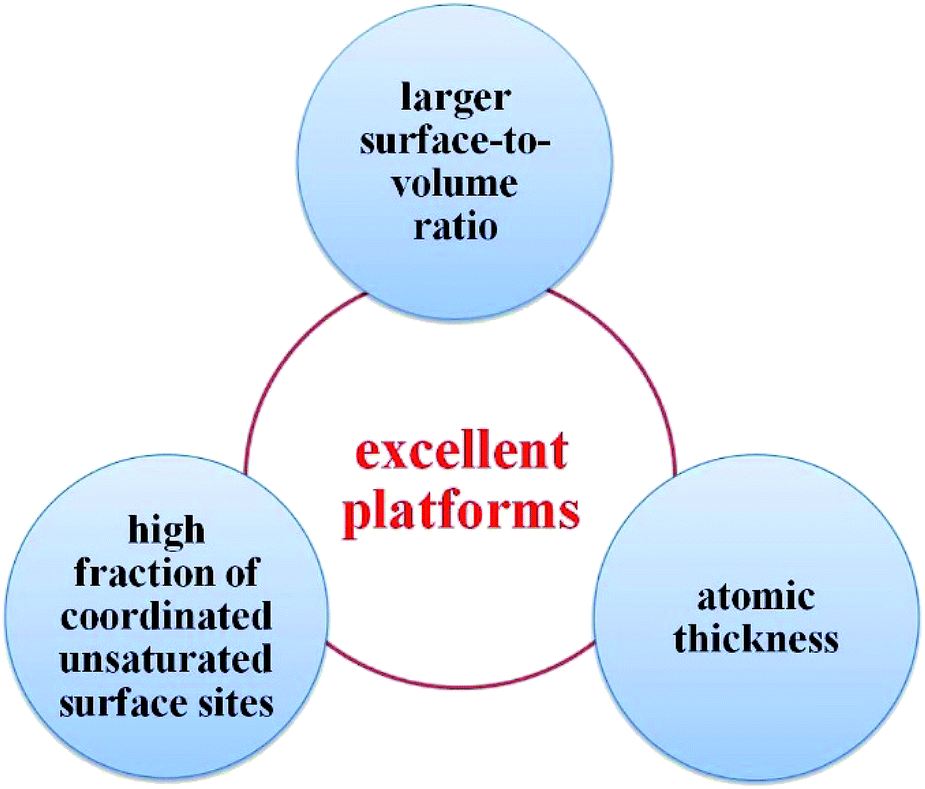 | ||
| Fig. 1 Schematic illustration of the superior advantages of 2D nanomaterials for photocatalytic applications in comparison with 0D and 1D materials. | ||
Given their extraordinary properties, 2D nanomaterials provide a wide range of opportunities for constructing diverse forms of composite photocatalysts with high activity and selectivity for CO2 reduction. Particularly, preparing fine-tuned and robust 2D nanomaterial photocatalysts is necessary to meet the practical requirements of CO2 reduction. Although there are some comprehensive reviews on 2D materials covering photocatalysts,6,72,73 a review on 2D nanomaterials as photocatalysts for CO2 reduction has never emerged. So we aim to prepare an overview of the recent progress in preparing 2D nanomaterial photocatalysts for CO2 reduction and provide insights into their unique properties. In this feature article, we summarize a series of typical 2D nanostructured photocatalysts for CO2 reduction, including graphene-based photocatalysts, graphitic carbon nitride-based photocatalysts, 2D metal oxide-based photocatalysts, 2D metal chalcogenide-based photocatalysts, 2D metal oxyhalide-based photocatalysts, and layered double hydroxide-based photocatalysts. Furthermore, based on the characteristics of 2D nanomaterials and the current status of research on photocatalytic CO2 reduction, the challenges and opportunities of 2D nanomaterials as prospective photocatalysts for CO2 reduction will also be discussed.
2. Nanostructured 2D materials as efficient photocatalysts for CO2 reduction
2.1 Graphene-based photocatalysts
Graphene, as a single-layer sp2-bonded carbon nanosheet with honeycomb rings, is a zero bandgap semiconductor, possessing extraordinary properties, including large specific surface area, high electronic conductivity, high transparency and good flexibility.56,108 All of these make graphene an ideal candidate for constructing new types of graphene-based photocatalysts to efficiently enhance the photocatalytic activity, such as photocatalytic pollutant degradation and hydrogen production.11,72,73,117,118 Until 2011, investigations on photocatalytic CO2 reduction using graphene-based photocatalysts were not reported.119 This is a relatively recent advancement compared to the development of other photocatalysts. Since the first exploratory study by Liang coupling graphene with TiO2 to improve the visible-light photocatalytic CO2 reduction activity, there has been an exponential increase in the scientific research on the subject of graphene-based nanocomposites for CO2 conversion. A summary of developments of graphene-based photocatalysts for CO2 reduction is shown in Table 1. Because of coupling graphene, there are some fascinating advantages of graphene-based photocatalysts for CO2 reduction, such as suppressing photogenerated carrier recombination, increasing the specific surface area, improving CO2 adsorption and activation, enhancing the photostability, improving nanoparticle (NP) dispersion, reducing NP size and enhancing light absorption.6 Therefore, a variety of articles on graphene-based photocatalysts for CO2 reduction have been reported.6,55,72,120 In view of the dimensionality and size difference, 2D graphene-based photocatalysts composed of two components can be classified into representative categories of graphene-based photocatalysts for photocatalytic CO2 reduction, namely: 0D/2D graphene-based photocatalysts, 1D/2D graphene-based photocatalysts and 2D/2D graphene-based photocatalysts (Fig. 2).| Dimensionality | Photocatalyst | Light source | Main products | Efficiency | Ref. |
|---|---|---|---|---|---|
| 2D | Graphene oxide (GO) | 300 W halogen lamp | CH3OH 0.172 mmol gcat−1 h−1 | 122 | |
| 0D/2D | TiO2-less defective graphene | Ultraviolet (365 nm) and visible illumination | CH4 7 times higher than P25 under visible light | 119 | |
| TiO2/RGO | 15 W energy-saving daylight bulbs | CH4 0.135 μmol gcat−1 h−1 | 151 | ||
| TiO2/GO | 450 W Xe lamp (250–388 nm) | CO 700 μmol gcat−1 h−1 | 152 | ||
| TiO2–graphene 2D sandwich-like hybrid nanosheets | 300 W Xe lamp | CH4 8 μmol g−1 h−1, C2H6 16.8 μmol g−1 h−1 | 131 | ||
| Anatase nitrogen-doped TiO2 nanoparticles with exposed {001} facets deposited on the graphene sheets (N–TiO2-001/GR) | 15 W energy-saving daylight lamp | CH4 3.70 μmol gcat−1 (10 h) | AQY = 0.0603% | 121 | |
| Doped-oxygen-rich TiO2–GO (OTiO2–GO) | 15 W energy-saving daylight bulbs | CH4 1.718 μmol gcat−1 (6 h) | 153 | ||
| Graphene oxide supported oxygen-rich TiO2 | 500 W Xe lamp (>400 nm) | CH4 3.450 μmol gcat−1 (8 h), CO, C2H4 and C2H6 | 154 | ||
| Graphitic carbon/hierarchically mesostructured TiO2 | 300 W Xe lamp | CH4 8.2 μmol gcat−1, CO 53.6 μmol gcat−1 (320 min) | 155 | ||
| TiO2/graphene–tourmaline | 500 W Xe lamp (<400 nm) | CH3OH 0.72 mmol g−1 h−1 | QE = 0.1072 | 156 | |
| P25/boron doped graphene nanosheets (P25/B–GR) | 300 W Xe lamp | CH4 2.50 μmol g−1 (2 h) | 157 | ||
| Cu/GO | 300 W halogen lamp | CH3OH and CH3CHO total 6.84 μmol gcat−1 h−1 | 130 | ||
| Reduced graphene-coated gold nanoparticles (rGO–AuNPs) | Xe lamp | HCOOH (>90%) CH3OH | QY = 1.52% | 129 | |
| ZnO/RGO | 500 W Xe lamp | CH3OH 45.8 μmol gcat−1 (10 h) | 123 | ||
| ZnO/RGO | 300 W Xe lamp | CH3OH 263.17 μmol gcat−1 (3 h) | 124 | ||
| Cu2O/RGO | 150 W Xe lamp | CO 46 ppmg−1 | AQY = 0.344% | 125 | |
| Cu2O/RGO | 500 W Xe lamp | CH3OH 41.5 μmol gcat−1 (10 h) | 126 | ||
| BiVO4/RGO | 500W Xe lamp | CH3CH2OH 15.4 μmol gcat−1 | 127 | ||
| Cu2Se–graphene | Visible light (300–450 nm) | CH3OH 2.63 μmol g−1 h−1 | 158 | ||
| CsPbBr3 QDs/GO | 100 W Xe lamp with an AM 1.5 G filter | CO 58.7 μmol g−1 CH4 29.6 μmol g−1(12 h) | 133 | ||
| Fe2O3/N-doped graphene | 300 W Xe lamp | CO 4 times higher than G–Fe2O3 | 159 | ||
| NiOx–Ta2O5–rGO | 400 W metal halide lamp | CH3OH 3.4 times higher than NiOx–Ta2O5 | 128 | ||
| Noble metal modified rGO/TiO2 (Pt, Pd, Ag and Au) | 15 W energy-saving daylight bulbs | CH4 1.70 μmol gcat−1 (6 h) | 160 | ||
| TiO2/CdS/RGO/Pt | AM 1.5 | CH4 0.0867 μmol h−1 (50 mg photocatalyst) | 161 | ||
| Porphyrin–graphene | Xe lamp (>400 nm) | CH4 57.38 μmol m−2 h−1, C2H2 112.89 μmol m−2 h−1 | 132 | ||
| Cobalt phthalocyanine immobilized on GO (CoPc–GO) | 20 W white cold LED flood light | CH3OH 78.789 μmol gcat−1 h−1 | 134 | ||
| Ruthenium trinuclear polyazine complex immobilized on graphene oxide | 20 W white cold LED flood light | CH3OH 3977.57 ± 5.60 μmol gcat−1 (48 h) | 135 | ||
| Chemically converted graphene coupled multianthraquinone substituted porphyrin (CCGCMAQSP) | 450 W Xe lamp (>420 nm) | HCOOH 110.55 μmol (0.5 mg photocatalyst 2 h) | 136 | ||
| CCG–BODIPY | 450 W Xe lamp (>420 nm) | HCOOH 144.2 ± 1.8 μmol (0.5 mg photocatalyst 2 h) | 137 | ||
| CCG–isatin-porphyrin | 450 W Xe lamp (>420 nm) | CH3OH 11.21 μM (0.5 mg photocatalyst 1 h) | 138 | ||
| 1D/2D | CdS nanorod-reduced graphene oxide | 300 W Xe lamp (>420 nm) | CH4 2.51 μmol h−1 g−1 | 141 | |
| WO3 nanobelt-graphene | 300 W Xe lamp (>400 nm) | CH4 0.89 μmol (0.1 g, 8 h) | 155 | ||
| Silver nanowire-doped reduced graphene oxide (RGO) integrated with a CdS nanowire network | 300 W Xe lamp (>420 nm) | CO 3.648 μmol g−1 CH4 1.153 μmol g−1 (4 h) | 162 | ||
| 2D/2D | TiO2 nanosheet-graphene | 100 W mercury vapor lamp (365 nm) | CH4 9.5 μmol m−2 h−1 | 143 | |
| Graphene–Ti0.91O2 hollow spheres | 300 W Xe lamp | CH4 1.14 μmol g−1 h−1 CO 8.91 μmol g−1 h−1 | 144 | ||
| Sandwich-like graphene/g-C3N4 | 15 W energy-saving daylight lamp | CH4 5.87 mmol gcat−1 (10 h) | 145 | ||
| RGO/protonated g-C3N4 | 15 W energy-saving daylight lamp | CH4 13.93 mmol gcat−1 (10 h) | Photochemical quantum yield 0.560% | 146 | |
| Z-scheme system | Fe2V4O13/RGO/CdS | Visible light (>420 nm) | CH4 2.30 μmol g−1 h−1 O2 3.80 μmol g−1 h−1 | 148 | |
| Metal sulfides/RGO/CoOx–BiVO4 | 300 W Xe lamp (>420 nm) | CO | 149 | ||
| CdS/RGO/TiO2 | 300 W Xe lamp | CH4 0.115 μmol g−1 h−1 | 150 |
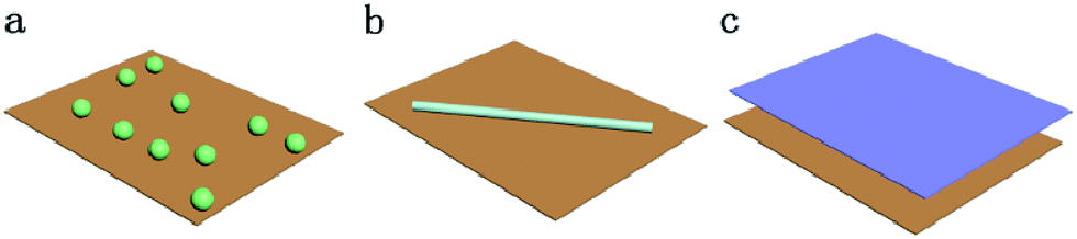 | ||
| Fig. 2 Schematic illustration of (a) 0D/2D, (b) 1D/2D, and (c) 2D/2D heterointerfaces. | ||
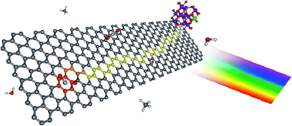 | ||
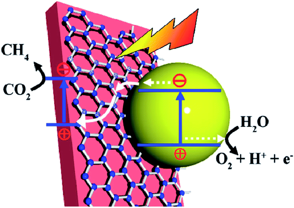
| Fig. 3 Proposed photocatalytic mechanism for graphene–TiO2 nanocomposites. The color scheme for the atoms is: carbon (gray), hydrogen (white), oxygen (red), and titanium (blue). Upon illumination, the photoexcited electron is injected into the graphene nanoplatelets, leaving behind a TiO2 confined hole (green). Due to its lower density of defects, electrons in SEG are able to diffuse farther (depicted as the yellow pathway), thus sampling a larger surface area for adsorbed CO2. Reprinted with permission from ref. 119. Copyright 2011 American Chemical Society. | ||
Recently, the synthesis of crystals with highly reactive facets has been one of the most effective strategies to achieve high photoconversion efficiency of CO2. Ong et al. reported a facile and reproducible solvothermal method to engineer anatase nitrogen-doped TiO2 nanoparticles with exposed {001} facets (N–TiO2-001) deposited on graphene (GR) sheets (N–TiO2-001/GR).121 The N–TiO2-001/GR nanocomposites exhibited high photocatalytic ability under visible light for the reduction of CO2 to CH4, which was approximately 11-fold stronger than that of pure TiO2-001. The enhancement of photocatalytic activity was attributed to the effective charge anti-recombination of graphene, high catalytic activity of {001} facets relative to the {101} facets, and high absorption of the visible light region. Moreover, the as-synthesized photocatalysts were active even under irradiation by a low-power 15 W energy-saving daylight lamp.
Unlike the zero bandgap nature of pristine graphene, graphene oxide (GO) has a wider bandgap and may serve as a potential candidate for a metal-free photocatalyst. Hsu et al. reported that graphene oxides were excellent visible-light-responsive photocatalysts for the photoconversion of CO2 to methanol by the modified Hummer's method.122 The CO2 conversion rate of the modified graphene oxide (GO-3) was 0.172 mmol gcat−1 h−1 under visible light, which was six-fold higher than that of pure TiO2. They also confirmed that methanol was produced directly through photocatalytic CO2 reduction instead of photo-dissociation of GOs by isotope tracer analyses with 13CO2. Moreover, a variety of oxygen moieties spreading throughout the GO surface endow it with good solution processability, providing an accessible platform to construct various graphene-semiconductor composites for CO2 conversion.120 Apart from graphene/TiO2 composites, composites of graphene and other photocatalysts, such as graphene/ZnO,123,124 graphene/Cu2O,125,126 graphene/BiVO4,127 and graphene/NiOx/Ta2O5 (ref. 128) have also been reported to be promising for the catalytic conversion of CO2 into solar fuels, as shown in Table 1.
The dispersion of noble metal nanoparticles such as Pt, Pd, Ag and Au on photocatalysts has been demonstrated to enhance the visible-light-responsive photocatalytic conversion of CO2 with H2O into hydrocarbon fuels. The high activity is mainly because of the injection of hot electrons or the facilitated generation of electron–hole pairs by the enhanced near field on plasmonic nanoparticles. For example, Kumar et al. synthesized reduced graphene-coated gold nanoparticles (r-GO–AuNPs), which exhibited excellent photocatalytic activity for CO2 reduction under visible-light.129 Compared to Pt–AuNPs, the as-synthesized catalysts showed excellent selectivity for HCOOH (>90%) and higher conversion efficiency. The photocatalytic activity was excellent and mainly attributed to reduced graphene layers, which could play a role in highly efficient electron acceptors and transporters to enhance utilization of hot electrons for plasmonic photocatalysts, as shown in Fig. 4. In 2014, Chen's group reported graphene oxide decorated with copper nanoparticles by a simple microwave process, which demonstrated significant enhancement in the photocatalytic activity toward solar fuel production.130
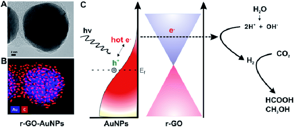 | ||
| Fig. 4 Schematic of graphene-coated gold nanoparticles for CO2 photoconversion. (A) HR-TEM image. (B) Energy dispersive X-ray mapping image of r-GO–AuNPs (Au (blue), carbon (red)). (C) Schematic representation of hot-electron generation and the role of the graphene layer as an efficient electron acceptor and transporter in generating hydrogen and subsequent conversion of CO2 into formic acid (HCOOH) and methanol (CH3OH). Reprinted with permission from ref. 129. Copyright 2016 American Chemical Society. | ||
Apart from the photocatalytic conversion of CO2 into single-carbon molecules, such as CO, CH4, CH3OH, and HCOOH, the reduction of CO2 to multi-carbon compounds by graphene-based nanocomposite photocatalysts has been scarce. Notably, some recent studies have proven that this process can be achieved over graphene-based nanocomposite photocatalysts. Tu et al. fabricated 2D sandwich-like graphene–TiO2 (G/TiO2) hybrid nanosheets in a binary ethylenediamine (En)/H2O solvent by a novel in situ simultaneous reduction-hydrolysis technique (SRH).131 When the prepared GO was reduced into graphene by En, TiO2 nanoparticles through the hydrolysis of titanium(IV) (ammonium lactato) dihydroxybis were formed simultaneously. During this process, a large number of TiO2 nanoparticles could be in situ uniformly loaded onto the graphene nanosheets to hinder their collapse and restacking, then formed a 2D sandwich-like structure (Fig. 5). On one hand, the specific structure exhibited higher specific surface area, more adsorption and reaction sites. On the other hand, the hybrid could favor the migration of photogenerated electrons from TiO2 to graphene, and thus improved the charge separation efficiency by the formation of d–π electron orbital overlap. Moreover, abundant Ti3+ was found on the surface of the G/TiO2 hybrid, caused by the reducing agent En. These Ti3+ ions could serve as photoinduced electron trapping sites and facilitated the electron–hole pair separation rate. As a result of these advantages, such assembled G/TiO2 exhibited efficient photocatalytic activity for the conversion of CO2 to valuable hydrocarbons (CH4 and C2H6) in the presence of water vapor. So, the authors concluded that the synergistic effect of the surface-Ti3+ sites and graphene was beneficial for the generation of C2H6, and the production rate of C2H6 increases with increase in the content of the incorporated graphene. Because of the G–TiO2 hybrid systems, ˙CH3 radicals may be adsorbed on the surface of graphene via π-conjugation between the unpaired electron of the radical and aromatic regions of graphene. The electron-rich graphene may help to stabilize the ˙CH3 species, which restrained the combination of ˙CH3 with H+ and e− to form CH4. Meanwhile, subsequent increasing accumulation of ˙CH3 on the graphene increased the chances of formation of C2H6 by the coupling of ˙CH3 instead of H+. Furthermore, porphyrin–graphene composite photocatalysts have been utilized for the photocatalytic reduction of CO2 to CH4 and acetylene (C2H2) under visible light irradiation.132 Bismuth vanadate/reduced graphene oxide (BiVO4/RGO) composites exhibited high photocatalytic activity of CO2 conversion into C2H5OH (15.4 μmol gcat−1) under the illumination of simulated sunlight.127
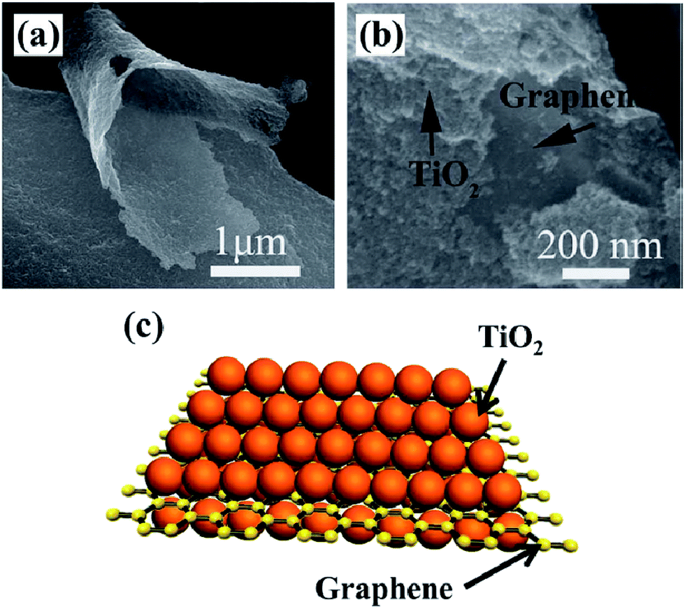 | ||
| Fig. 5 SEM image (a, b) and schematic illustration (c) of sandwich like G/TiO2. Reprinted with permission from ref. 131. Copyright 2013 Wiley-VCH. | ||
In recent years, a variety of graphene-based photocatalysts coupling perovskite quantum dots,133 transition metal complexes,134,135 supramolecular metal complexes,132 and bio-enzymes136–138 have emerged for CO2 reduction, due to their excellent visible-light absorption, suitable redox potential, high quantum yield and high selectivity of products.
Furthermore, Yu et al. successfully prepared a typical RGO–CdS nanorod composite photocatalyst for the photocatalytic reduction of CO2 to CH4 by a microwave-assisted hydrothermal method.141 RGO is regarded as an effective co-catalyst for enhancing photocatalytic CO2 reduction, and the optimal RGO–CdS photocatalyst exhibits excellent reduction activity of CO2 to CH4, which was 10 times higher than that of pure CdS NRs. This was because RGO not only acted as an electron acceptor and transporter to efficiently separate the photogenerated charge carriers, but also enhanced the adsorption and activation of CO2 molecules over the RGO–CdS composite, thus enhancing the photocatalytic reduction of CO2 to CH4. Furthermore, Liu and co-workers explored a ternary hybrid structure of 1D silver nanowire-doped RGO integrated with a CdS nanowire network, which exhibited enhanced visible-light-driven photocatalytic performance toward artificial photosynthesis, including the liquid-phase selective photoreduction of nitroaromatic compounds to amines, splitting of water to hydrogen, and the gas-phase CO2 reduction. Wang et al. developed graphene–WO3 nanobelt composites by a facile in situ hydrothermal method.142 By loading graphene, the conduction band minimum value of WO3 can be elevated, leading to enhancement of its photocatalytic activity for CO2 reduction.
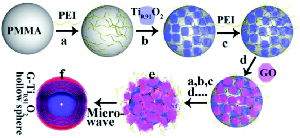 | ||
| Fig. 6 Schematic illustration of the procedure for preparing the LBL-assembled multilayer-coated spheres consisting of titania nanosheets and GO nanosheets, followed by microwave reduction of GO to G. Reprinted with permission from ref. 144. Copyright 2015 Wiley-VCH. | ||
 | ||
| Fig. 7 Schematic illustration of the photocatalytic conversion of CO2 into CH4 over a Fe2V4O13/RGO/CdS Z-scheme system. (Fe2V4O13 ECB: −0.55 eV, EVB: 1.28 eV; CdS ECB: −0.52 eV, EVB: 1.88 eV vs. NHE). Reprinted with permission from ref. 148. Copyright 2015 Royal Society of Chemistry. | ||
2.2 Graphitic carbon nitride-based photocatalysts
As a fascinating two-dimensional conjugated polymer, graphitic carbon nitride (g-C3N4) has attracted widespread attention as a metal-free and visible-light-active photocatalyst in the arena of solar energy conversion and environmental remediation.82,87,163,164 This is due to its unique band structure, excellent thermal and chemical stability, non-toxicity, relative ease of synthesis and earth-abundant nature. Since Wang and co-workers first reported g-C3N4 as a novel photocatalyst that exhibited photoactivity for H2 generation under visible-light irradiation,165 the number of articles on g-C3N4-based photocatalysts shot up dramatically. However, the photocatalytic rate of pristine g-C3N4 is still low, due to the high recombination rate of charge carriers, small specific surface area, low electric conductivity, and lack of absorption above 460 nm.84,85,166 To overcome these shortcomings, some measures on structural modifications, copolymerization, elemental doping, coupling with metals or noble metals, incorporation with other semiconductors or metal phosphides, and so on have been taken to improve its photocatalytic efficiency.82,84,85,87,163,164,167–171 In this part, we present a summary of g-C3N4-based photocatalysts for CO2 reduction, as shown in Table 2.| Dimensionality | Photocatalyst | Light source | Main products | Efficiency | Ref. |
|---|---|---|---|---|---|
| 2D | Porous g-C3N4 | 300 W Xe lamp (>420 nm) | CO | 173 | |
| U–g-C3N4 (derived from urea) | 300 W Xe lamp (>420 nm) | CH3OH 15.1 μmol C2H5OH 10.8 μmol (0.2 g photocatalyst 12 h) | AQE = 0.18 | 174 | |
| Bulk g-C3N4 | 300 W Xe lamp | CH3CHO | 175 | ||
| g-C3N4 nanosheets | 300 W Xe lamp | CH4 | 175 | ||
| C3N4–MCF (using MCF as templates) | UV-visible light | CH3CHO 8.0 μmol g−1, CH4 0.05 μmol g−1 (1 h) | 176 | ||
| C3N4–SBA-15 (using SBA-15 as templates) | UV-visible light | CH3CHO 3.5 μmol g−1, CH4 0.78 μmol g−1 (1 h) | 176 | ||
| Ultra-thin nanosheet assemblies of g-C3N4 | 300 W Xe lamp | CH4 1.39 μmol h−1 g−1, CH3OH 1.87 μmol h−1 g−1 | 177 | ||
| Sulfur-doped g-C3N4 | 300 W Xe lamp | CH3OH 1.12 μmol g−1 (3 h) | 178 | ||
| C3N4 derived from urea and barbituric acid | 300 W Xe lamp (>420 nm) | CO 31.1 μmol h−1 (30 mg photocatalyst) | 179 | ||
| Amine-functionalized g-C3N4 | 300 W Xe lamp | CH4 0.34 μmol h−1 g−1, CH3OH 0.28 μmol h−1 g−1 | 180 | ||
| Hydroxyl-rich g-C3N4 nanosheets | 300 W Xe lamp (>420 nm) | CH4 7.47 μmol g−1 (8 h) | 181 | ||
| K-incorporated amino-rich C3N4 | 1 sun simulated sunlight from a Xe lamp | CO and CH4 5.4 and 5.6 times higher than urea-polymerized g-C3N4 | 182 | ||
| Thiourea derived g-C3N4 | 300 W Xe lamp (>200 nm) | CO 10.5 μmol gcat−1 CH4 1.2 μmol gcat−1 (5 h) | 183 | ||
| 0D/2D | Pt/g-C3N4 | 300 W Xe lamp | CH4, CH3OH and HCHO | 184 | |
| Pt/g-C3N4 | 15 W energy-saving daylight bulb | CH4 13.02 μmol gcat−1 (10 h) | 185 | ||
| Pd/g-C3N4 | 300 W Xe lamp | CO, C2H5OH and CH4 | 186 | ||
| N–TiO2/g-C3N4 | 300 W Xe lamp | CO 14.73 μmol (0.1 g photocatalyst 12 h) | 187 | ||
| TiO2/B-doped g-C3N4 | 300 W Xe lamp (>420 nm) | CH4 106 μmol (0.2 g photocatalyst 8 h) | 188 | ||
| CdS/g-C3N4 | 250 W lamp 365 nm | Methyl formate 1352.07 μmol h−1 gcat−1 | 189 | ||
| ZnO/g-C3N4 | 500 W Xe lamp | CO, CH3OH, CH4 and C2H5OH, total 45.6 μmol h−1 gcat−1 | 190 | ||
| WO3/g-C3N4 | Light-emitting diode (435 nm) | CH3OH | 191 | ||
| In2O3/g-C3N4 | 500 W Xe lamp | CH4 159.2 ppm (20 mg photocatalyst 4 h) | 192 | ||
| CoOx/g-C3N4 | 300 W Xe lamp (>420 nm) | CO | 193 | ||
| AgX/g-C3N4 (X = Cl and Br) | 15 W energy-saving daylight Lamp | CH4 10.92 μmol gcat−1 (10 h) | 194 | ||
| AgCl/C3N4 | 15 W energy-saving daylight lamp | CH4 | 195 | ||
| CeO2/g-C3N4 | 300 W Xe lamp | CO 0.590 μmol h−1 CH4 0.694 μmol h−1 (50 mg photocatalyst) | 196 | ||
| SnO2/B–P codoped g-C3N4 | 300 W Xe lamp (>420 nm) | CH4 49 μmol (0.2 g photocatalyst 8 h) | 197 | ||
| Ru complex/C3N4 | 450 W Xe lamp | CO and HCOOH | 201 | ||
| RuP/C3N4 | Visible light (>400 nm) | HCOOH 67.7 μmol CO 17.7 μmol | AQY = 5.7% | 202 | |
| 400 W, high-pressure Hg lamp | HCOOH 1.5 μmol g−1 CO | AQY = 5.7% | 204 | ||
| Ru(II) complex/C3N4 | Visible light (>400 nm) | HCOOH | 206 | ||
| RuRu′/Ag/C3N4 nanosheets | Visible light (>400 nm) | HCOOH | 205 | ||
| Zeolitic imidazolate framework (Co-ZIF-9)/g-C3N4 | Visible light (>420 nm) | CO 20.8 μmol | AQY = 0.9% | 152 | |
| [Co(bpy)n]2+/g-C3N4 | Xe lamp (300–795 nm) | CO | AQY = 1.6% | 198 | |
| Co4@g-C3N4 | 300 W Xe lamp (>420 nm) | CO 107 μmol g−1 h−1 | 200 | ||
| Co-porphyrin/C3N4 | 300 W Xe lamp (>400 nm) | CO 17 μmol g−1 h−1 | AQY = 0.8% | 199 | |
| UiO-66/g-C3N4 | 300 W Xe lamp (400 nm < λ < 800 nm) | CO 9.9 μmol gCN−1 h−1 | 208 | ||
| Carbon nanodot/g-C3N4 | Xe lamp (>400 nm) | CH4 29.23 μmol gcat−1, CO 58.82 μmol gcat−1 (10 h) | AQY = 0.076% | 209 | |
| Red phosphor/g-C3N4 | 500 W Xe lamp | CH4 295 μmol h−1 g−1 | 210 | ||
| B4C/C3N4 | 300 W Xe lamp (405 nm < λ < 723 nm). | CH4 0.84 μmol g−1 h−1 | 211 | ||
| 1D/2D | NaNbO3 nanowires/g-C3N4 | 300 W Xe lamp (>420 nm) | CH4 6.4 μmol h−1 g−1 | 218 | |
| Pt–g-C3N4/KNbO3 | 300 W Xe lamp (>420 nm) | CH4 0.25 μmol h−1 (100 mg) | 219 | ||
| 2D/2D | Sandwich-like graphene/g-C3N4 | 15 W energy-saving daylight bulb | CH4 5.87 μmol gcat−1 (10 h) | 190 | |
| rGO/g-C3N4 | 15 W energy-saving daylight bulb | CH4 13.93 μmol gcat−1 (10 h) | AQY = 0.560% | 146 | |
| Mg–Al–LDH/C3N4 | 500 W Xe lamp | CH4 3.7 μmol (200 mg photocatalyst 24 h) | QE = 0.093% | 221 | |
| MnO2/g-C3N4 | 300 W Xe lamp | CO 9.6 μmol g−1 h−1 | 222 | ||
| AgBr/g-C3N4/nitrogen-doped graphene | 300 W Xe lamp (>400 nm) | CH3OH 105.89 μmol g−1, C2H5OH 256.45 μmol g−1 | QE = 3.41% | 220 | |
| Bi2WO6/C3N4 | 300 W Xe lamp (>420 nm) | CO 5.19 mmol g−1 h−1 | 223 | ||
| Z-scheme | WO3/g-C3N4 | Light-emitting diode | CH3OH 2.4 times higher than pure g-C3N4 | 191 | |
| Ag3PO4/g-C3N4 | 500 W Xe lamp (>420 nm) | CH4, CH3OH, C2H5OH and CO, total 57.5 μmol h−1 gcat−1 | 224 | ||
| SnO2−x/g-C3N4 | Simulated sunlight irradiation | CH4, CH3OH and CO, total 22.7 μmol h−1 gcat−1 | 170 | ||
| BiOI/g-C3N4 | 300 W Xe lamp (>400 nm) | CO 4.86 μmol g−1 h−1, CH4 0.18 μmol g−1 h−1 | 225 | ||
| Bi2WO6/g-C3N4 | 300 W Xe lamp (>420 nm) | CO 5.19 μmol g−1 h−1 | 223 | ||
| ZnO/g-C3N4 | 300 W Xe lamp | CH3OH 0.6 μmol h−1 g−1 | 226 |
Different from graphene, g-C3N4 is a metal-free polymeric semiconductor photocatalyst with a moderate band gap of 2.7–2.8 eV.172 Because the conduction band (CB) edge of g-C3N4 is sufficiently negative to reduce CO2 into hydrocarbons, such as CH4 (−0.24 V), CH3OH (−0.38 V), HCHO (−0.48 V) and HCOOH (−0.61 V), the photocatalytic CO2 conversion could be achieved by the direct use of g-C3N4 photocatalysts (Fig. 8).82,168 Dong et al. first reported that g-C3N4 fabricated from melamine hydrochloride could effectively convert CO2 to CO photocatalytically in the presence of water vapor under visible-light without any cocatalyst.173 Mao et al. and Niu et al. revealed the effect of g-C3N4 microstructures on the selectivity of photocatalytic CO2 reduction under visible light.174,175 Ovcharov and co-workers synthesized porous C3N4 using bulk and hard template (SBA-15 and MCF) pyrolysis of melamine.176 They found that acetaldehyde was the major product of the photocatalytic CO2 reduction regardless of the morphology of C3N4. Recently, Xia et al. prepared hierarchical g-C3N4 assembled by amine-functionalized ultra-thin nanosheets by a stepwise NH3-mediated thermal exfoliation approach.177 The as-synthesized g-C3N4 photocatalyst exhibited remarkably enhanced CO2 photoreduction performance compared to the unmodified g-C3N4 due to reasons including enhanced light harvesting, increased CO2 adsorption, strong redox ability of charge carriers, more surface active sites, and improved charge carrier transfer and separation.
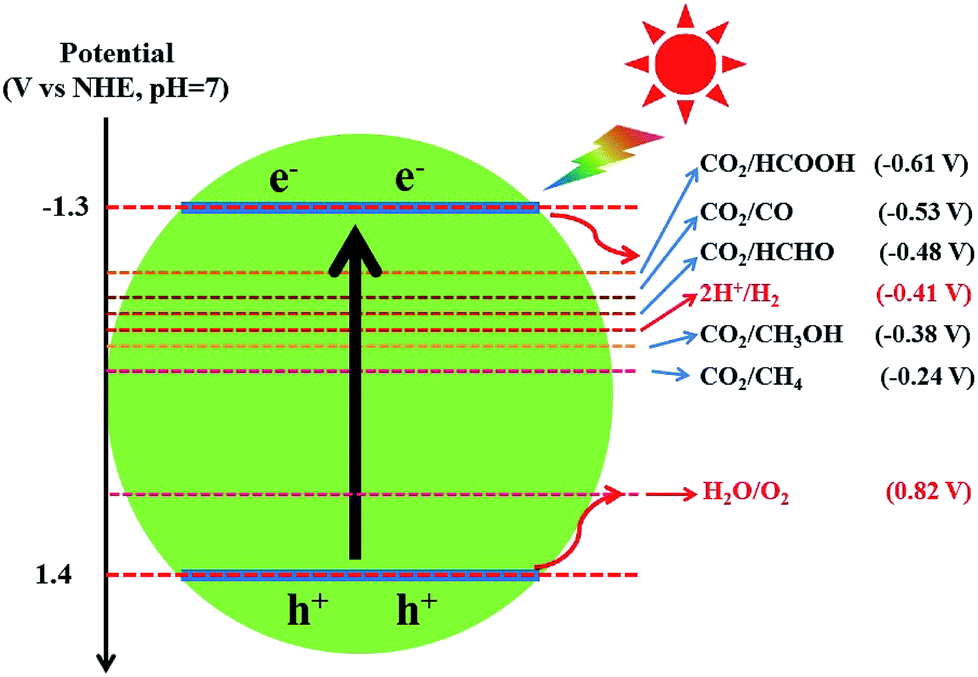 | ||
| Fig. 8 The redox potentials of the relevant reactions with respect to the estimated position of the g-C3N4 band edges at pH 7. | ||
Doping is one of the most effective strategies for improving photocatalytic activity due to its effectiveness in broadening the optical response range of semiconductor materials.168 For instance, Wang et al. synthesized sulfur-doped g-C3N4 (S–CN) with excellent photocatalytic CO2 reduction activity by simple thermolysis of thiourea.178 The band gap of S–CN was narrowed from 2.7 to 2.63 eV (Fig. 9), so more light can be absorbed and utilized to improve the photocatalytic activity. Then, DFT studies confirmed that the photoinduced electrons could easily jump from the VB to the impurity state or from the impurity state to the CB of S–CN owing to the sulfur doping, which induced additional electrons, resulting in spin polarization. As a result, the photocatalytic activity for CO2 reduction to CH3OH of the appropriately tuned S–CN was nearly 2.5 times that of undoped g-C3N4.
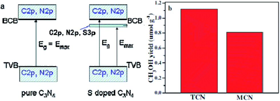 | ||
| Fig. 9 (a) Schematic of the band structure of pure g-C3N4 (left) and S-doped g-C3N4 (right); (b) comparison of photocatalytic CH3OH production over S-doped g-C3N4 (TCN) and undoped g-C3N4 (MCN) at 3 h under UV-vis light irradiation. Reprinted with permission from ref. 178. Copyright 2015 Elsevier. | ||
Besides this, various methods of g-C3N4 surface engineering were shown to be effective for enhancing photocatalytic CO2 reduction activity, including copolymerization,179 amine functionalization,180 hydroxylation,181 and chemical activation with KOH.182 Qin and co-workers fabricated barbituric acid-modified g-C3N4 by the copolymerization of urea with barbituric acid co-monomer.179 The modified samples showed enhanced optical absorption, suppressed electron–hole recombination rates, and improved charge transfers, which made them efficient heterogeneous photocatalysts for conversion of CO2 to CO under visible light. Hence, the optimal sample showed 15-fold-enhanced photocatalytic activity for CO2 conversion into CO compared to the parent sample.
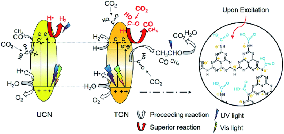
In 2016, Wang et al. reported thiourea derived g-C3N4 (TCN) with inferior activity in CO2 reduction under visible light irradiation, but TCN exhibited higher CO2 conversion efficiency at 200–400 nm UV light irradiation compared to g-C3N4 synthesized from urea (UCN) and commercial TiO2 (P25).183 They found that –NHx species present in abundance, that was responsible for CO2 activation, the enhanced reducing ability of photo-excited electrons under UV light and the higher photo-excited electron–hole separation efficiency could all contribute to the excellent performance of TCN in the CO2 photocatalytic reduction using >200 nm UV light (Fig. 10). However, its visible-light activity was relatively weak because of its limited surface area.
 | ||
| Fig. 10 Schematic mechanism of CO2 photocatalytic reduction with H2O over TCN and UCN under >200 nm UV-vis light irradiation. Reprinted with permission from ref. 183. Copyright 2016 Elsevier. | ||
Apart from the above-mentioned nanostructure engineering of g-C3N4, such as structural modifications, elemental doping, and surface engineering, a cocatalyst or other semiconductor materials can be loaded onto the surface of g-C3N4 to construct the heterojunctions, which enhance their charge separation and photostability, and lead to excellent photocatalytic performance for CO2 reduction. Next, according to the different dimensions and components, we categorized g-C3N4-based heterojunction photocatalysts into three types, such as 0D/2D g-C3N4-based photocatalysts, 1D/2D g-C3N4-based photocatalysts and 2D/2D g-C3N4-based photocatalysts.
Besides metal/g-C3N4-based photocatalysts, composites of g-C3N4 and semiconductor photocatalysts, such as g-C3N4/TiO2,187,188 g-C3N4/CdS,189 g-C3N4/ZnO,190 g-C3N4/WO3,191 g-C3N4/In2O3,192 g-C3N4/CoOx (ref. 193) and g-C3N4/other semiconductors have also been reported for photocatalytic conversion of CO2 into solar fuels, as shown in Table 2. For example, Zhou et al. synthesized composites (g-C3N4–N–TiO2) consisting of g-C3N4 and N-doped TiO2 by a facile calcination, which exhibited enhanced photocatalytic performance for CO2 reduction in the presence of water vapor at room temperature.187 They found that the product composition could be tuned by varying the preparation parameters. In another study, In2O3/g-C3N4 composite photocatalysts were prepared through a simple solvothermal method by Cao and co-workers, and the hybrid structures exhibited improved photocatalytic activities for H2 generation and CO2 reduction.192 Such a remarkable improvement in the photocatalytic performance was attributed to the highly effective interfacial charge transfer across the In2O3/g-C3N4 heterojunction (Fig. 11).
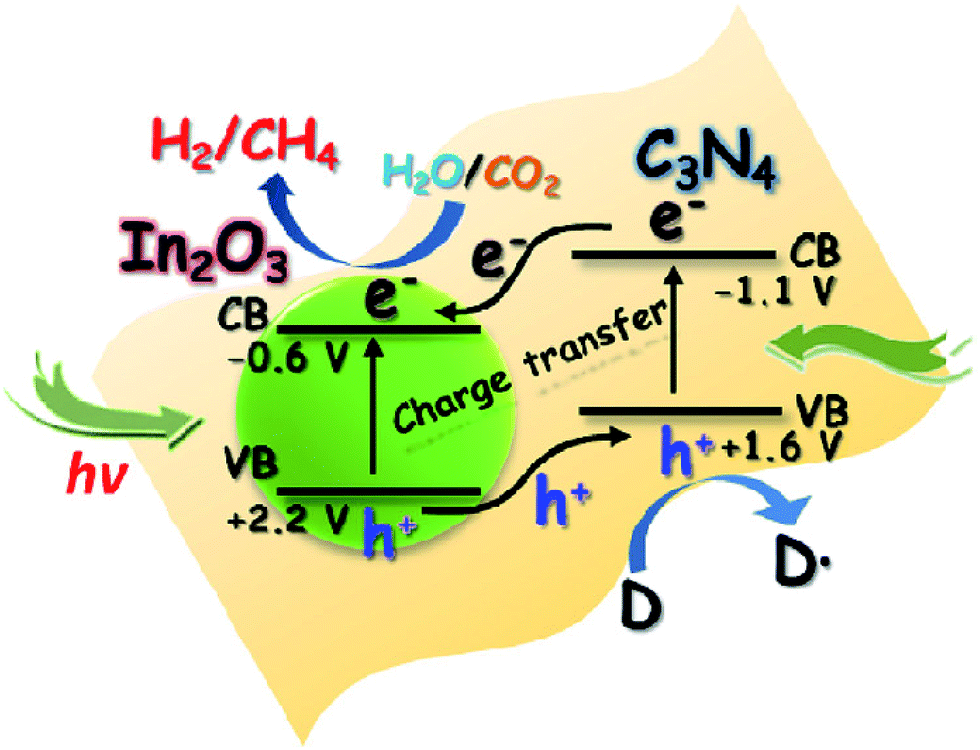 | ||
| Fig. 11 Schematic illustration of the photocatalytic process for H2 evolution and CO2 reduction on the In2O3–g-C3N4 nanohybrids. Reprinted with permission from ref. 192. Copyright 2014 Elsevier. | ||
In 2016, Ong and co-workers reported AgX/protonated g-C3N4 (X = Cl and Br) heterojunction photocatalysts via a sonication-assisted deposition–precipitation approach.194 The highest photocatalytic performance of the optimal 30AgBr/pCN sample was 34.1 and 4.2 times greater than that of pure AgBr and pCN, respectively. Comparing different halide ions, the photocatalytic activity of 30AgBr/pCN was 1.3 times greater than that of the optimal 30AgCl/pCN. The improvement in the photocatalytic activity of 30AgBr/pCN was ascribed to the formation of the AgBr/pCN heterojunction. The overlapping band potentials of pCN and AgBr matched well, which could form a type II heterojunction to enhance the separation efficiency of photogenerated electron–hole pairs (Fig. 12). Additionally, the formation of metallic Ag upon reduction of some AgBr nanoparticles during the photocatalytic process played a prominent role in the localized SPR effect by absorbing the visible light, thus generating electron–hole pairs, and further promoting the interfacial charge transfer across the Ag/AgBr interface. As a continuation from the previous work, the same research group found a similar phenomenon on an AgCl/C3N4 hybrid photocatalyst by using a protonation-assisted deposition–precipitation method.195
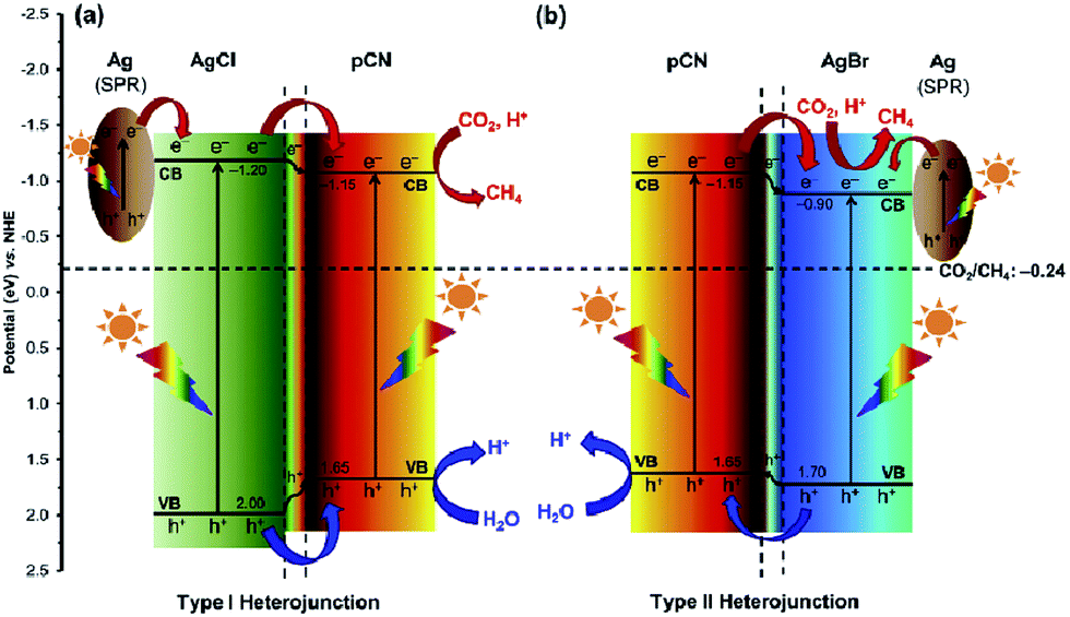 | ||
| Fig. 12 Schematic illustration of the band structures of (a) Ag/AgCl/pCN and (b) Ag/AgBr/pCN hybrid nanocomposites for the photoreduction of CO2 with H2O to CH4 under light irradiation. Reprinted with permission from ref. 194. Copyright 2016 Elsevier. | ||
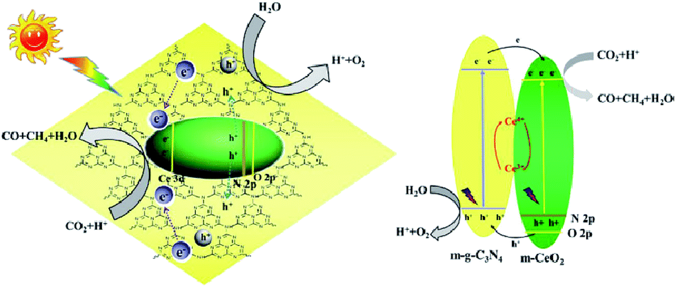
Li et al. fabricated mesostructured CeO2/g-C3N4 (m-CeO2/g-C3N4) using SiO2 nanoparticles as a hard template.196 The remarkably enhanced performance of the heterogeneous nanocomposites for CO2 photoreduction was ascribed to the synergistic influence of mutual activations of g-C3N4 and CeO2. The migration of photogenerated electrons from g-C3N4 to m-CeO2 and their trapping by Ce4+ led to the prevention of combination of photogenerated electrons and holes in g-C3N4 (g-C3N4 activation) and the generation of Ce3+ from Ce4+ reduction by the trapped electrons in m-CeO2 (CeO2 activation), both of which benefited the activity enhancements of CO2 reduction (Fig. 13).
 | ||
| Fig. 13 Schematic illustration of the proposed charge transfer mechanism in the CeO2/g-C3N4 heterojunction photocatalysts upon light irradiation. Reprinted with permission from ref. 196. Copyright 2016 Elsevier. | ||
Recently, Raziq et al. synthesized SnO2-coupled boron and phosphorus co-doped g-C3N4 (SO/B–P–C3N4) nanocomposites for effective photocatalytic conversion of CO2.197 Compared to the bare g-C3N4 nanosheets, the resulting SO/B–P–C3N4 nanocomposite showed enhanced photocatalytic performance for CO2 conversion to CH4 by ∼9 times under visible-light, which was due to the extended visible-light absorption from 460 to 550 nm after B–P co-doping, and the improved charge separation via the dopant-induced surface states and the coupled SO.
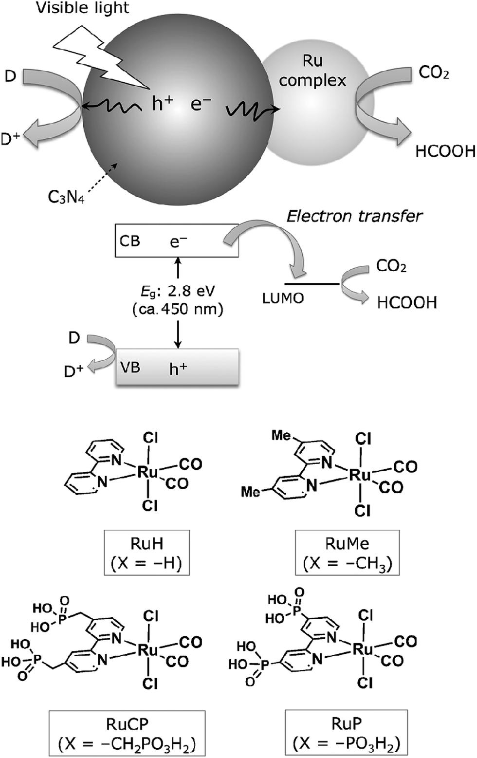
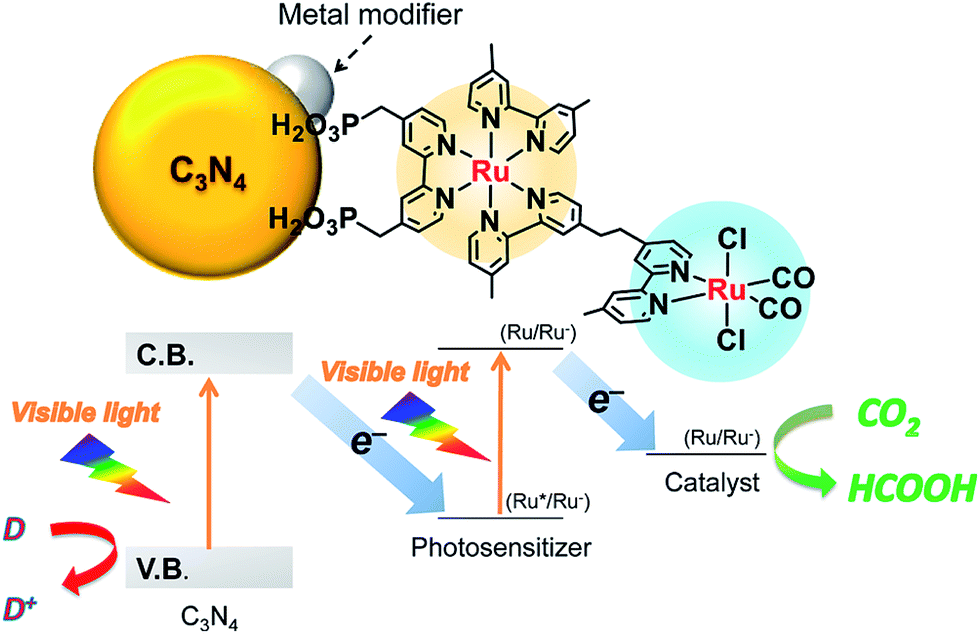
In addition, coupling cobalt,152,193,198–200 ruthenium,201–207 rhenium and zirconium208 complexes on g-C3N4 nanosheets to form heterogeneous photocatalysts has also been regarded as a promising approach to improve the CO2 reduction of g-C3N4 under visible light irradiation. Maeda et al. did a series of research on ruthenium complex/g-C3N4 composites for photocatalytic CO2 reduction. In 2013, they developed a Ru complex/C3N4 heterogeneous photocatalyst system, by dispersing g-C3N4 powder in a methanol solution containing an appropriate amount of trans(Cl)-[Ru{4,4′-(CH2PO3H2)2-2,2′-bipyridine}(CO)2Cl2] (RuCP) with continuous stirring at room temperature overnight.201 In this system, the ruthenium complex and C3N4 worked as the catalytic and the light-harvesting unit, respectively. The simple binary hybrid photocatalyst showed efficient photocatalytic conversion of CO2 into HCOOH under visible-light, with a selectivity of >80% and a turnover number (TON) of >200 using triethanolamine as an electron donor. They clarified that the origin of the HCOOH produced was derived from CO2 reduction via using isotope tracer experiments with 13CO2. After that, they optimized the mononuclear Ru complexes by using four different Ru complexes, which are represented as RuH, RuMe, RuP, and RuCP, to increase the efficiency of the photocatalytic CO2 reduction (Fig. 14).202 RuP/C3N4 exhibited the best performance, with a selectivity of >80%, high TON (>1000) and apparent quantum yield value (5.7%) at 400 nm. Then, they found that the solvent had a strong influence on product selectivity.203 In 2016, they designed a new hybrid system RuRu′/Ag/mpg-C3N4 involving Ag-modified mesoporous g-C3N4 (mpg-C3N4) and a RuII binuclear complex for CO2 reduction.204 The photocatalytic CO2 reduction of this system followed the Z-scheme electron-transfer mechanism including step-by-step photoexcitation of C3N4 and RuRu′, as shown in Fig. 15. The hybrid RuRu′/Ag/mpg-C3N4 photocatalyst produced a TON of ∼33![[thin space (1/6-em)]](https://www.rsc.org/images/entities/char_2009.gif) 000 for 48 h (with respect to the molar amount of RuRu′), which was 30 times greater than that reported previously using C3N4 modified with a mononuclear Ru(II) complex. However, the selectivity and TON of this system during CO2 reduction in aqueous media obviously dropped (at most <80% and 660, respectively). Very recently, by replacing mesoporous g-C3N4 with g-C3N4 (NS–C3N4) nanosheets in this system, RuRu′/Ag/NS–C3N4 exhibited a good TON (>2000) and high CO2 reduction selectivity (approximately 98%) for photocatalytic reduction of CO2 to HCOOH in aqueous solution.205 These values represent the highest yet reported for a powder-based photocatalytic system for CO2 reduction under visible light in an aqueous environment.
000 for 48 h (with respect to the molar amount of RuRu′), which was 30 times greater than that reported previously using C3N4 modified with a mononuclear Ru(II) complex. However, the selectivity and TON of this system during CO2 reduction in aqueous media obviously dropped (at most <80% and 660, respectively). Very recently, by replacing mesoporous g-C3N4 with g-C3N4 (NS–C3N4) nanosheets in this system, RuRu′/Ag/NS–C3N4 exhibited a good TON (>2000) and high CO2 reduction selectivity (approximately 98%) for photocatalytic reduction of CO2 to HCOOH in aqueous solution.205 These values represent the highest yet reported for a powder-based photocatalytic system for CO2 reduction under visible light in an aqueous environment.
 | ||
| Fig. 14 CO2 reduction using a Ru complex/C3N4 hybrid photocatalyst, along with structures of the Ru complexes used. Reprinted with permission from ref. 202. Copyright 2015 Wiley-VCH. | ||
 | ||
| Fig. 15 Z-scheme CO2 reduction using a hybrid of C3N4 and a binuclear Ru(II) complex. Reprinted with permission from ref. 204. Copyright 2016 American Chemical Society. | ||
Besides this, coupling some metal free nanoparticles, such as carbon nanodots (CDs),209 red phosphor,210 or boron carbide (B4C)211 with g-C3N4 to form a heterogeneous photocatalyst could also improve its performance for photocatalytic CO2 reduction. Recently, Ong et al. developed 0D/2D carbon nanodot (CD)-hybridized protonated g-C3N4 (pCN) (CD/pCN) heterojunction photocatalysts for the photocatalytic reduction of CO2 by means of electrostatic attraction.209 The total amounts of CH4 and CO generated from the optimal sample (3 wt% of CDs) were 3.6 and 2.28 times higher than those generated with pure pCN, respectively, which was mainly attributed to the synergistic interaction between pCN and CNDs (Fig. 16). That is to say, the well contacted heterojunction interfaces accelerated the effective migration of photoexcited electrons from pCN to CNDs, and then hampered the charge recombination. This was confirmed by the first-principles density functional theory (DFT) calculation.
 | ||
| Fig. 16 Charge transfer and separation in the enhanced photoreduction of CO2 to CO and CH4 using CND/pCN samples under visible-light or simulated solar irradiation. Reprinted with permission from ref. 209. Copyright 2017 Springer. | ||
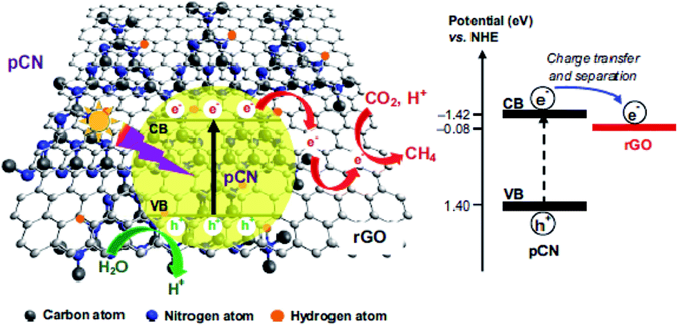
Ong and co-workers fabricated sandwich-like graphene–g-C3N4 nanocomposites via a one-pot impregnation-thermal reduction approach using urea and graphene oxide as precursors for the reduction of CO2 to CH4 under visible light.190 Moreover, they found that the absorption band edge of the as-synthesized sample exhibited a slight red shift. This phenomenon was attributed to the formation of a C–O–C bond as a covalent cross-linker between graphene and g-C3N4. The optimal sample exhibited 2.3 times higher activity than pure g-C3N4, which was ascribed to the increased electron charge transfer across the interface of the graphene–g-C3N4 heterojunction to impede recombination. The article is the first report that the graphene-g-C3N4 hybrid nanocomposites showed visible-light photocatalytic activity for CO2 reduction to CH4. In another closely related study by the same research group in the same year, they synthesized a novel 2D/2D rGO–hybridized pCN (rGO/pCN) nanostructure constituted of the negatively charged rGO and the positively charged pCN by π–π stacking and electrostatic attraction (Fig. 17).146 The amounts of CH4 evolution of the rGO/pCN photocatalysts were remarkably larger than that of rGO/pure g-C3N4 (rGO/CN) under a low-power energy-saving daylight bulb, on account of forming an intimate contact between rGO and pCN across the heterojunction interfaces for efficient charge transfer and separation over rGO/pCN.
 | ||
| Fig. 17 Schematic illustration of the charge transfer and separation in the rGO/pCN nanocomposite for CO2 reduction with H2O to CH4 under visible light illumination. Reprinted with permission from ref. 146. Copyright 2015 Elsevier. | ||
In the same year, AgBr nanoparticles (NPs) supported on g-C3N4-decorated nitrogen-doped graphene (NG) ternary nanocomposites (ACNNG-x) were constructed by Li and his group, which presented excellent photocatalytic performance for organic contaminant degradation and CO2 reduction under visible light.220 Compared with the single component, this ACNNG-x superhybrid photocatalytic system could greatly overcome the drawbacks and realized high charge separation efficiency, strong redox ability, and long-term stability. Such excellent performance was attributed to the distinctive heterojunction system, which could successfully improve the photoinduced carrier separation efficiency and help to suppress the recombination of electrons–holes, leaving more charge carriers to form reactive species.
In addition, 2D–2D Mg–Al–LDH/C3N4,221 MnO2/g-C3N4,222 and Bi2WO6/g-C3N4 (ref. 223) have also been reported for photocatalytic CO2 reduction.
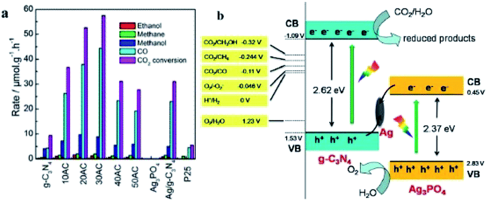
He and co-workers fabricated an Ag3PO4/g-C3N4 composite photocatalyst by an in situ deposition method and investigated it in the photocatalytic reduction of CO2 to fuels (CH4, CO, CH3OH, and C2H5OH) for the first time.224 The optimal Ag3PO4/g-C3N4 photocatalyst showed a CO2 conversion rate of 57.5 μmol h−1 gcat−1, which was 6.1 times higher than that of pristine g-C3N4 under simulated sunlight irradiation (Fig. 18a). On account of this phenomenon, a Z-scheme mechanism was proposed. Since the low conduction band of Ag3PO4 (ECB = 0.45 eV) indicated that the electrons cannot reduce CO2 to fuels, the traditional type II heterojunction (also known as a double-charge transfer mechanism) could not explain the above performance of Ag3PO4/g-C3N4. However, Ag nanoparticles were formed due to the photoreduction of Ag+ from Ag3PO4 under light irradiation, which might act as a charge transmission bridge to construct the Ag3PO4/g-C3N4 Z-scheme system (Fig. 18b). Because the CB edge of Ag3PO4 is more negative than the Fermi level of metallic Ag, the photogenerated electrons moved from the CB of Ag3PO4 to metallic Ag. Simultaneously, the holes in the VB of g-C3N4 moved from the VB of g-C3N4 to metallic Ag and combined with the electrons. This type of charge transmission efficiently enhanced the separation of electron–hole pairs and allowed the electrons and holes to remain on the CB of g-C3N4 and VB of Ag3PO4, respectively. Due to the negative ECB of g-C3N4, these electrons have strong reducibility and can easily reduce CO2 to CO, CH4, CH3OH, and CH3CH2OH, which is consistent with the results in Fig. 18a.
 | ||
| Fig. 18 (a) Photocatalytic reduction of CO2 over Ag3PO4/g-C3N4 composites; (b) photocatalytic mechanism scheme of the Ag3PO4/g-C3N4 composite. Reprinted with permission from ref. 224. Copyright 2015 American Chemical Society. | ||
In addition, the same group synthesized another solid-state Z-scheme SnO2−x/g-C3N4 photocatalyst by a simple calcination approach for photocatalytic CO2 reduction.170 Based on the Z-scheme mechanism, the electrons from the CB of SnO2−x combined with the photogenerated holes from the VB of g-C3N4, resulting in a strong reducing power of the excited electrons in g-C3N4 to reduce CO2 to energy fuels such as CO, CH4, and CH3OH. Due to the direct Z-scheme mechanism, without employing any electron mediators, the rate of photocatalytic CO2 reduction of the optimal composites was 4.3- and 5-fold enhancement compared to those of g-C3N4 and P25.
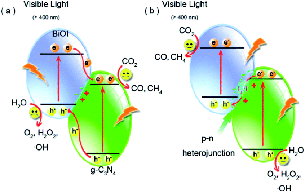
Though the number of reports on constructing Z-scheme photocatalysts for enhanced catalytic activity has gone up rapidly, direct experimental evidence on how the photogenerated electrons transfer across the junctions, especially all-solid state Z-scheme photocatalysts, has never been reported. Recently, a series of BiOI/g-C3N4 photocatalysts were prepared via a simple deposition approach by Wang and co-workers to clarify the charge transfer process.225 The as-synthesized BiOI/g-C3N4 composites exhibited more highly efficient photocatalytic activity than pure g-C3N4 and BiOI and the product yields changed remarkably depending on the reaction conditions such as irradiation light wavelength (Fig. 19). What's more important was that an indirect Z-scheme charge transfer mode was verified by detecting the electron mediator I3−/I− pairs experimentally. The reaction mechanism was further proposed based on the detection of the intermediate ˙OH and H2O2. This work may be useful for rationally designing new types of Z-scheme photocatalysts and providing some illuminating insights into the Z-scheme transfer mechanism.
 | ||
| Fig. 19 Schematic diagram of photoinduced electron–hole separation processes: (a) double-charge transfer mechanism and (b) Z-scheme mechanism. Reprinted with permission from ref. 225. Copyright 2016 American Chemical Society. | ||
Besides this, some other g–C3N4-based Z-scheme photocatalysts, such as Bi2WO6/g-C3N4 (ref. 223) and ZnO/g-C3N4 (ref. 226) have also been constructed, which showed high-efficient performance in the photocatalytic CO2 conversion to fuels.
2.3 2D metal oxide nanomaterial-based photocatalysts
Over the past four decades, various metal oxides such as TiO2, ZnO, SnO2, WO3 and Fe2O3 have been extensively explored as photocatalysts for CO2 photoreduction to solar fuels. Because of the excellent stability, nontoxicity, low cost and easy availability, TiO2 has been one of the most widely studied photocatalysts, while TiO2 based 2D nanosheets through exfoliation of layered titanate have also drawn considerable attention.227 The reports on TiO2 based 2D nanosheets focused on photodegradation and water splitting, but the amount of CO2 reduction is limited. Xu et al. synthesized anatase TiO2 single crystals composed of TiO2 ultrathin nanosheets (2 nm in thickness) with 95% of exposed {100} facet, which exhibited about 5 times higher activity in both H2 evolution and CO2 reduction than the TiO2 cuboids with 53% of exposed {100} facets.228 For the TiO2 nanosheets, on one hand, the higher percentage of exposed {100} facets and larger surface area could offer more surface active sites. One the other hand, the superior electronic band structure which resulted from the higher percentage of the {100} facet contributed to expanding their activity.Zou's group reported a series of TiO2 based photocatalysts for photocatalytic CO2 conversion to fuels,29,144,229–232 among which robust hollow spheres consisting of alternating TiO2 nanosheets and graphene nanosheets for CO2 conversion have been mentioned above.144 After that, the same group designed multilayer Ti0.91O2/CdS hollow spheres consisting of alternating ultrathin Ti0.91O2 nanosheets and CdS nanoparticles via layer-by-layer self-assembly to achieve an all solid-state Z-scheme system with 7-times enhancement of the CH4-production rate relative to pure Ti0.91O2 hollow spheres.232 This was due to the efficient separation of photogenerated electron–hole pairs, which greatly prolonged the lifetime of charge carriers. In 2015, Liu and co-workers reported nanosheet-assembled hierarchical titanate yolk@shell microspheres with engineered multilevel microstructures and efficient photocatalytic CO2 reduction performance by a one-pot solvothermal method.233
Moreover, ultrathin, single-crystal WO3 nanosheets with about 4–5 nm in thickness, which corresponded to six repeating unit cells of monoclinic WO3 along the c axis, were synthesized with a laterally oriented attachment of tiny WO3 nanocrystals formed via a solid–liquid phase arc discharge route.25 Because of size-quantization effects in this ultrathin nanostructure that extended the WO3 band gap, the WO3 nanosheets exhibited enhanced performance for photocatalytic reduction of CO2, which did not happen in the bulk form (Fig. 20).
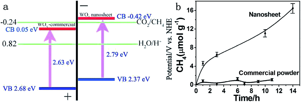 | ||
| Fig. 20 (a) Calculated band positions of WO3 nanosheets and commercial WO3, relative to the redox potential of CO2/CH4 in the presence of water; (b) CH4 generation over the nanosheets and commercial powder as a function of visible light irradiation time (λ > 420 nm). Reprinted with permission from ref. 25. Copyright 2012 American Chemical Society. | ||
In addition to the above 2D transition metal oxides, Cu(II) nanocluster-grafted Nb3O8− nanosheets,234 SnNb2O6 nanosheets,70,235 ultrathin Bi2WO6 nanosheets and hierarchical microspheres scaffolded from ultrathin ZnGa2O4 nanosheets22 used as photocatalysts for CO2 reduction have been reported as shown in Table 3.
| Categories | Photocatalyst | Light source | Main products | Efficiency | Ref. |
|---|---|---|---|---|---|
| 2D metal chalcogenide | TiO2 ultrathin nanosheets (2 nm) | 300 W Xe lamp (λ > 300 nm) | CH4 5.8 ppm g−1 h−1 | 228 | |
| Graphene/Ti0.91O2 hollow spheres | 300 W Xe lamp | CH4 1.14 μmol g−1 h−1, CO 8.91 μmol g−1 h−1 | 144 | ||
| Ti0.91O2/CdS | 300 W Xe lamp | CH4 0.1 μmol h−1 (0.01 g photocatalyst) | 232 | ||
| Amine-functionalized TiO2 nanosheet-assembled yolk@shell microspheres | 300 W Xe lamp (>400 nm) | CH3OH 2.1 μmol h−1 g−1 | 162 | ||
| WO3 nanosheets | 300 W Xe lamp (>420 nm) | CH4 16 μmol g−1 (14 h) | 25 | ||
| Cu(II) nanocluster-grafted Nb3O8− nanosheets | Hg–Xe lamp (240–300 nm) | CO | 234 | ||
| SrNb2O6 nanoplates | Xe lamp (λ = 300–780 nm) | CO 1.66 μmol, CH4 0.33 μmol (0.01 g photocatalyst 10 h) | 235 | ||
| Monolayer SnNb2O6 | 300 W Xe lamp (>420 nm) | CH4 110.9 μL h−1 g−1 | 70 | ||
| Hierarchical microspheres scaffolded from ultrathin ZnGa2O4 nanosheets | 300 W Xe lamp with an IR cut filter | CH4 6.9 ppm h−1 (0.1 g photocatalyst) | 22 | ||
| 2D metal chalcogenide | MoS2–TiO2 | UV-vis light | CH4 10.6 μmol g−1 h−1 | 244 | |
| MoS2/Bi2WO6 | 300 W Xe lamp (>420 nm) | CH3OH 36.7 μmol gcat−1, C2H5OH 36.6 μmol gcat−1 (4 h) | 245 | ||
| WSe2–graphene | 500 W Xe lamp (>300 nm) | CH3OH 5.0278 μmol g−1 h−1 | QE = 0.8159 | 246 | |
| 2D metal oxyhalide | BiOCl nanoplates | 500 W Xe lamp | CO 8.1 μmol g−1 (8 h) | 257 | |
| BiOCl nanosheets | 300 W Xe lamp (a 250–380 nm UVREF filter) | CH4 41.48 μmol g−1 (8 h) | 256 | ||
| Bi4O5Br2 nanosheets | 300 W Xe lamp (>400 nm) | CO 2.73 μmol g−1 h−1, CH4 2.04 μmol g−1 h−1 | AQY = 0.21% | 255 | |
| BiOI/g-C3N4 | 300 W Xe lamp (>400 nm) | CO 4.86 μmol g−1 h−1, CH4 0.18 μmol g−1 h−1 | 225 | ||
| Olive-green few-layered BiOI | 300 W Xe lamp (>420 nm) | CO 0.615 μmol h−1, CH4 0.063 μmol h−1 (0.15 g photocatalyst) | AQY = 0.14% | 258 | |
| BiOI nanosheets | 300 W Xe lamp | CO 0.259 μmol h−1 CH4 0.089 μmol h−1 (0.05 g photocatalyst) | 259 | ||
| Bi2O4-decorated BiOBr nanosheets | Xe lamp | CH4 3.7 μmol g−1, CO 5.2 μmol g−1 (2 h) | 276 | ||
| BiOBr nanosheets | Xe lamp | CO 4.45 μmol g−1 h−1 | 277 | ||
| Layered double hydroxides | Zn–Cu–M(III) (M = Al, Ga) LDHs | 500 W Xe lamp | CO 620 μmol h−1 gcat−1 | 262 | |
| Zn–Cu–Ga LDH | 500 W Xe lamp | CH3OH 0.49 μmol h−1 gcat−1 | 264 | ||
| Zn–Cu–Ga LDH | 500 W Xe lamp | CO and CH3OH | 265 | ||
| Ag or Au/Zn–Ga–LDH | 500 W Xe lamp | CO 30 nmol h−1 gcat−1, CH3OH 201 nmol h−1 gcat−1 | 266 | ||
| M2+–M3+ LDHs (M2+ = Mg2+, Ni2+, and Zn2+; M3+ = Al3+, Ga3+, and In3+) | 200 W Hg–Xe lamp | CO | 268 | ||
| Ni–Al LDH (Ni/Al = 4) | 400 W high pressure Hg lamp | CO and CH4 | 269 | ||
| Fluorinated Mg–Al LDH and Ni–Al LDH | 400 W high pressure Hg lamp | CO 93.3 μmol (0.5 g photocatalyst 20 h) | 278 | ||
| M2+–M3+ LDHs (M2+ = Co2+, Ni2+, Cu2+, Zn2+; M3+ = V3+, Cr3+, Mn3+, Fe3+) | 400 W high-pressure Hg lamp | CO 147.1 μmol (0.5 g photocatalyst 5 h) | 271 | ||
| Mg–Al–LDH/C3N4 | 500 W Xe lamp | CH4 3.7 μmol (200 mg photocatalyst 24 h) | QE = 0.093% | 221 | |
| Cu–M–Al LDH (M = Mg, Zn, Ni) | 500 W Xe lamp (380–760 nm) | CH3OH 0.210 mmol g−1 h−1 | 273 | ||
| Ce3+–Ce4+ LDHs | 300 W Xe lamp | CO 1.68 μmol g−1 h−1 | 274 | ||
| Ru nanoparticle modified Mg–Al LDHs | 300 W Xe lamp | CH4 277 mmol h−1 g−1 | 272 | ||
| Others | Carbon-doped BN nanosheets | 300 W Xe lamp (>420 nm) | CO 9.3 μmol (50 mg photocatalyst 2 h) | 275 |
2.4 2D metal chalcogenide-based photocatalysts
2D metal chalcogenide nanosheets, such as MoS2, WS2, SnS2, TiS2, MoSe2, WSe2, etc., have been attracting much attention recently owing to their excellent catalytic activity and low cost compared to noble metals.15,55,91,92,94,236–238 Among 2D metal chalcogenide nanosheets, MoS2, composed of hexagonal layers of Mo atoms sandwiched between two layers of sulfur atoms, has been one of the most promising semiconductors due to its thickness-dependent band gap and abundance in nature as molybdenite.95,239 Bulk MoS2 material is a semiconductor with an indirect band gap of about 1.3 eV, which is unsuitable for photocatalytic reactions because of its insufficient oxidation/reduction potential. However, the isolated MoS2 nanosheets possess a direct bandgap of 1.96 eV owing to the quantum confinement effect, which endows MoS2 nanosheets with extraordinary photoinduced catalytic ability.91,239 With these extraordinary properties, MoS2 has frequently acted as a catalyst or non-noble metal co-catalyst combined with other photocatalysts to form a heterojunction to enhance the photocatalytic activity for photodegradation and water splitting.91,93,236,239–243 Until now, besides MoS2, many other TMD nanosheets, such as WS2 and NiS2, have also been reported as excellent cost effective catalysts or cocatalysts.94,237 Although there have been numerous reports on 2D metal chalcogenide nanosheets as electrocatalysts or photocatalysts for the production of hydrogen, only few reports focus on the photocatalytic reduction of CO2 by using 2D metal chalcogenides as photocatalysts.Recently, Tu et al. fabricated 2D MoS2–TiO2 hybrid nanojunctions, which exhibited photocatalytic activity for CO2 conversion in aqueous solution.244 MoS2 nanosheets proved to be an efficient co-catalyst, showed superior activity and selectivity for reducing CO2 into CH3OH in aqueous solution to the metal cocatalysts (like Pt, Au, and Ag) under UV-vis light irradiation. This was because the Mo-terminated edges with the metallic character and a high d-electron density benefit the electron transfer and the stabilization of CHxOy intermediates (Fig. 21).
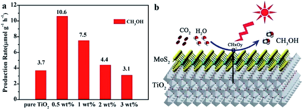 | ||
| Fig. 21 (a) Comparison of the photocatalytic activity of pure TiO2 nanosheets and MoS2/TiO2 hybrid nanosheets with different MoS2 amounts for CO2 photoreduction. (b) Schematic illustration of the charge separation and transfer in the MoS2/TiO2 system for photoreduction of CO2 to CH3OH. Mo sites especially Mo-terminated edges on MoS2 nanosheets benefit the stabilization of intermediate products (CHxOy). Reprinted with permission from ref. 244. Copyright 2017 Royal Society of Chemistry. | ||
In the same year, few-layer MoS2 loaded hierarchical flower-like Bi2WO6 (MoS2/Bi2WO6) nanocomposites were synthesized via an impregnation-calcination method by Dai et al.245 The as-synthesized MoS2/Bi2WO6 nanocomposites exhibited considerable enhancement of activity for photocatalytic reduction of CO2 under visible light as compared to pure Bi2WO6. This was because the few layered MoS2 as a cocatalyst has an intimate interfacial contact with Bi2WO6, which enhanced the visible light absorption, charge transfer and separation, thus boosting their photocatalytic activity. Furthermore, a possible photocatalytic mechanism was also proposed. The CO32−, HCO3− and H2CO3 generated in CO2 aqueous solution would be the reactive substrates during the photoreduction reaction, proving the thermodynamic feasibility of CO2 photoreduction.
Ali and co-workers reported WSe2–graphene nanocomposites prepared via ultra-sonication and tested them in terms of the photocatalytic reduction of CO2 to CH3OH under irradiation with UV/visible light.246 Adding a sacrificial agent (Na2S/Na2SO3) to the WSe2–graphene nanocomposites could further improve the photocatalytic efficiency. After coupling with graphene, the binary structure promoted the electron transport and decelerated the recombination of the electron–hole pairs compared to pure WSe2. This was the first article which reported that the WSe2 chalcogenide family could be used as the photocatalyst for CO2 reduction.
2.5 2D metal oxyhalide-based photocatalysts
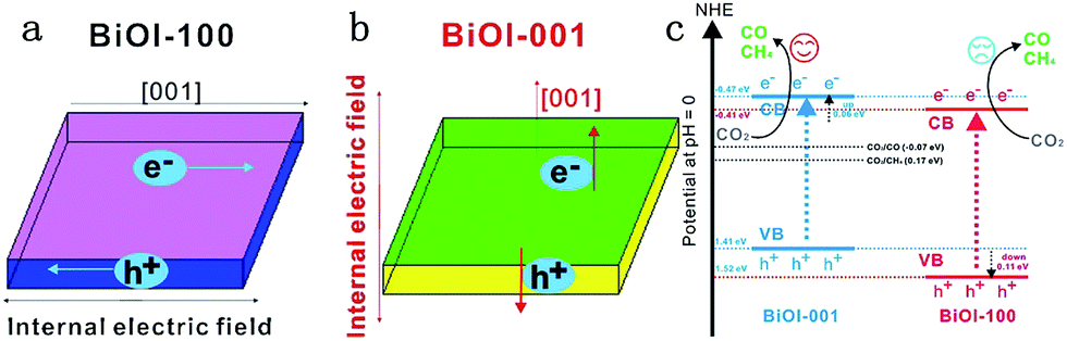
Bismuth oxyhalides, BiOX (X = Cl, Br, and I), have recently attracted much attention for their unique layered structure, and excellent optical and electrical properties.247,248 Bismuth oxyhalides have a layered structure consisting of [Bi2O2]2+ layers sandwiched between two slabs of halogen ions, resulting in the formation of self-built internal static electric fields and thus inducing outstanding photocatalytic activity.249,250 Particularly, BiOX (X = Cl, Br and I) 2D nanosheets and 3D hierarchical structures with 2D nanoflakes displayed remarkable photocatalytic activity for photocatalytic removal of pollutants in air, water and biological contaminants.251–254 For instance, Wang et al. prepared porous BiOCl micro-flowers constructed from ultrathin nanosheets (4 nm) with nearly 100% {001} facets exposed, which possessed a strong photooxidative ability to degrade the dye pollutants (RhB, MB, MO) directly and easily.251 After that, Guan and co-workers reported high solar photocatalytic activity in ultrathin BiOCl nanosheets (2.7 nm) with almost fully exposed active {001} facets for photodegradation of RhB.253 However, because of the high positive conduction band minimum (CBM) of BiOX photocatalysts, the photocatalytic reduction activity was very low and the number of reports on photoreduction of CO2 or H2O using BiOX was very few.247,248,255 Given this predicament, many strategies, including bismuth-rich,255 thickness-ultrathin,256 oxygen vacancy,257 and construction of Z systems,225 have been employed to achieve photocatalytic CO2 reduction activity, as shown in Table 3.Ye et al. reported olive-green few-layered (2.8 nm with four layers) BiOI with expanded spacing of the (001) facets and oxygen vacancy, which showed much higher photocatalytic activity for CO2 reduction than pure bulk BiOI under visible or near-infrared (NIR) light (Fig. 22).258 The enhanced photocatalytic activity was due to the expanded facets spacing and oxygen vacancy of few-layered BiOI, thereby enhancing the separation efficiency of photoinduced carriers and photon absorption efficiency.
 | ||
| Fig. 22 (a) Model showing the direction of the internal electric field in BiOI-100; (b) model showing the direction of the internal electric field in BiOI-001 and (c) the photocatalytic mechanism of facet-dependent photocatalytic activity of BiOI nanosheets for CO2 photoreduction. Reprinted with permission from ref. 259. Copyright 2016 Elsevier. | ||
In the same year, the same group fabricated Bi4O5Br2 microspheres assembled using ultrathin nanosheets (about 3.7 nm) via a glycerol precursor route.255 Due to the thickness-ultrathin and bismuth-rich strategies, the as-synthesized Bi4O5Br2 displayed excellent photocatalytic reduction activity for CO2 conversion compared to pure BiOBr and ultrathin BiOBr under visible light. Furthermore, they found that the thickness-ultrathin strategy was responsible for enhancement of the CO generation while the bismuth-rich strategy was responsible for improving the CH4 generation for photoreduction of CO2.
2.6 Layered double hydroxides-based photocatalysts
Layered metal hydroxides (LMHs) include layered single metal hydroxides (LSHs) and layered double hydroxides (LDHs).99,260 This section mainly discusses LDH-based photocatalysts for photocatalytic CO2 conversion. LDHs, of the general formula [MII1−xMIIIx(OH)2]x+·(An)−x/n·mH2O (in which M = metal and A = interlayer anion), widely treated as basic materials for CO2 capture and storage, are also applied in photocatalytic CO2 reduction, because of their strong sorption capacity for CO2 in the layered space and tunable semiconductor properties (photocatalytically active sties, bang gap etc.) as a result of the choice of metal cations.98,261,262 In 2011, Ahmed et al. first reported that Zn–Cu–M(III) (M = aluminum, gallium) LDHs could be used as a photocatalyst for CO2 conversion using hydrogen as a reductant under UV-vis light.262 Among the various LDHs, Zn–Al LDH showed good promise for CO2 reduction to CO, whereas Cu-containing LDH was effective for CO2 reduction to methanol. In order to improve the photocatalytic activity for CO2 reduction, a reverse photofuel cell was designed using WO3 as the photooxidation catalyst of water and a Cu–Zn–Ga LDH as the photoreduction catalyst of CO2 (Fig. 23).263 Furthermore, the same group did a series of research studies to improve the photocatalytic activity and selectivity of LDH (Cu, Zn, Ga, Al) via different methods, like changing the rate of Cu and Zn, replacing interlayer carbonate anions, and using Pt, Pd and Au as cocatalysts.264–267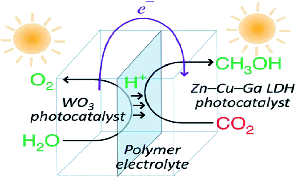 | ||
| Fig. 23 Schematic illustration of the flow of materials and electrons during photocatalytic CO2 conversion in reverse photofuel cell-1 consisting of WO3 and LDH1. Reprinted with permission from ref. 263. Copyright 2014 Royal Society of Chemistry. | ||
Besides this, Teramura and Tanaka's group synthesized LDHs to reduce CO2 into CO in water, and found that various M2+–M3+ LDHs (M2+ = Mg2+, Ni2+, and Zn2+; M3+ = Al3+, Ga3+, and In3+) exhibited photocatalytic activity.268 After that, the same group found that Ni–Al LDH from chloride exhibited the highest activity and selectivity for CO formation among the various kinds of LDHs, and the added Cl− could enhance the selectivity to CO.269 Cl− in an aqueous solution acts as a hole scavenger under UV light irradiation and it is oxidized into ClO−, ClO3−, and ClO4.270 In 2016, they prepared 16 different kinds of transition metal containing M2+–M3+ LDHs (M2+ = Co2+, Ni2+, Cu2+, and Zn2+; M3+ = V3+, Cr3+, Mn3+, and Fe3+) and investigated their photocatalytic activities for CO2 reduction in an aqueous NaCl solution under UV light irradiation.271 Among these LDHs, Ni–V LDH exhibited the highest activity for the CO evolution. It is estimated that a combination of V3+ and Cl− played a significant role in the high photocatalytic activity and selectivity toward CO formation in an aqueous solution.
In general, the above mentioned LDH based materials suffer from the efficiency bottleneck of a μmol h−1 g−1 (catalyst) or lower rate. Recently, Ren et al. designed a novel 2D nanostructured catalyst constructed using an ultrathin Mg–Al LDH matrix and Ru nanoparticles (denoted as Ru@FL-LDHs) (Fig. 24).272 In this composite, the exfoliated LDHs and Ru nanoparticles activated CO2 and H2, respectively. The maximum yield rate for CH4 generation of Ru@FL–LDHs in a flow-type reaction system is 277 mmol h−1 g−1 (catalyst), which remarkably exceeds all previous reports on LDH-based catalysts. The high-efficient and continuous CO2 hydrogenation is achieved via using the flow-type reaction system, which makes it possible to achieve industrial production in the future.
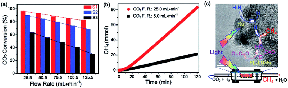 | ||
| Fig. 24 (a) Photothermal conversion of CO2 over Ru loaded catalysts under different flow rates (F.R.) of CO2 and H2 mixture. Samples: S1. Ru@FL-LDHs; S2, Ru@LDHs; S3, Ru@SiO2. (b) Cumulative yield of CH4 over Ru@FL-LDHs. Reaction conditions: catalyst, 150 mg; light source, 300 W xenon lamp (light intensity, ≈10 suns); H2/CO2 flow rates (F.R.), 20.5 mL min−1/5.0 mL min−1, or 100.5 mL min−1/25.0 mL min−1. (c) Schematic exhibition of targeting and simultaneous activation of CO2 and H2 as well as the hydrogenation process over Ru@FL-LDHs. Reprinted with permission from ref. 272. Copyright 2017 Wiley-VCH. | ||
In addition, Cu–M–Al LDHs (M = Mg, Zn, Ni),273 Ce3+–Ce4+ LDHs,274 and the self-assembly of Mg–Al–LDH/C3N4 (ref. 221) have also been reported for photocatalytic CO2 reduction.
2.7 Other 2D nanosheets
In addition to the above mentioned six types of materials, carbon-doped h–BN nanosheets were synthesized, which had functionalities to catalyse hydrogen and oxygen evolution from water as well as CO2 reduction under visible light illumination.275 The ternary B–C–N alloy featured a delocalized two-dimensional electron system with sp2 carbon incorporated in the h–BN lattice where the bandgap could be adjusted by the amount of incorporated carbon to produce unique functions. Such photocatalysts of lightweight elements provide a new insight into fabricating active metal-free photocatalysts and demonstrate the great potential of using economic materials for efficient solar fuel production.3. Conclusion and outlook
Overall, in this review, we have outlined the recent progress in constructing 2D nanomaterials-based photocatalysts for CO2 reduction. Because these 2D materials possess many fascinating properties, such as good physical and chemical stability, large surface area, high electron mobility, ultrathin lamellar nature and abundant surface active sites, use of some ultrathin nanomaterials-based photocatalysts that are few-atoms thick or the introduction of 2D materials into various semiconductor-based photocatalysts results in remarkable improvement of photocatalytic activity for CO2 reduction. Although a number of above-mentioned literature studies have demonstrated that 2D nanomaterials-based photocatalysts have achieved some significant advances in photocatalytic CO2 reduction, there is still a very long way to go to achieve the process of artificial photosynthesis for practical application using 2D based nanomaterials as photocatalysts due to the unsatisfactory light harvesting, low conversion efficiency, lack of selectivity to specified products, and complex photocatalytic mechanisms.Firstly, from the material synthesis point of view, it is still a great challenge to realize large-scale, high and uniform quality 2D nanomaterials with controllable thickness for industry or commercialization in the future. Because the photocatalytic activity of photocatalysts depends on their composition and morphology, ultrathin 2D nanomaterials with desired morphologies and compositions should be fabricated to achieve high activity and selectivity for photocatalytic CO2 conversion.
Furthermore, the underlying mechanisms of enhanced photocatalytic efficiency toward CO2 reduction by 2D nanomaterial photocatalysts are still not well understood and must be systematically studied, including adsorption/desorption of CO2 and intermediate products. Owing to the complex multielectron transfer processes and various redox potentials in photocatalytic CO2 conversions, a variety of products, such as CH4, HCOOH, CH2O, and CH3OH, can be formed after the photocatalytic CO2 reduction. It was found that the presence of 2D nanomaterials can affect the formation of different products during the photocatalytic CO2 conversion. The exploration of reaction mechanisms is vital to elucidate the fundamental improvements and further optimization of the photocatalytic activity and selectivity in the future. This depends not only on advanced characterization techniques, but also on theoretical computational simulations of different aspects. Advanced materials characterization techniques such as scanning tunneling microscopy (STM), electron microcopy, atomic force microscopy, X-ray absorption fine-structure (XAFS) and terahertz time-domain spectroscopy could be of great help. Furthermore, the in situ monitoring of the CO2 concentration during the photocatalytic CO2 reduction or isotopic 13CO2 labeling should also be performed to demonstrate the carbon-containing products originating from CO2 photoreduction. In addition, theoretical calculations using density functional theory (DFT) could illustrate the roles of 2D nanomaterials in photocatalysis, which could provide us with efficient guidance for their rational experimental design.
In addition, there is no standard protocol to evaluate the photocatalytic performance in CO2 reduction. It is because the final activity and selectivity of CO2 conversion is determined by certain conditions, including the intensity and spectrum of light irradiation, pH of the solution, reaction temperature, humidity, temperature, CO2 pressure, the amount and kind of sacrificial agent, and mass of photocatalysts. However, apparent quantum efficiency (AQE) under the same photocatalytic reaction conditions could measure the CO2 photoreduction efficiency, which is calculated by using the number of used photons and the incident photon number, according to eqn (1) (when the products from the CO2 photoreduction system are complex, the number of reacted electrons is the sum of the reacted electrons involved in the generation of each product4,48,279,280).
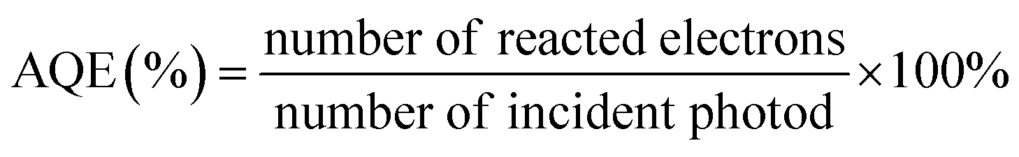 | (1) |
Finally, the exploration of novel 2D nanomaterials made of earth abundant, nontoxic, light-stable, scalable and low cost materials or modification of the existing 2D nanomaterials by fine tuning the structural, compositional, band-gap and surface reaction sites, is highly encouraged. Such modification will further promote light harvesting and retarding the charge recombination to realize artificial photosynthesis for practical application.
Conflicts of interest
There are no conflicts to declare.Acknowledgements
This work was supported by the National Natural Science Foundation of China (No. 21473090, U1663228), the National Basic Research Program of China (973 Program, 2013CB632404) and a project funded by the Priority Academic Program Development of Jiangsu Higher Education Institutions.References
- S. N. Habisreutinger, L. Schmidt-Mende and J. K. Stolarczyk, Angew. Chem., Int. Ed., 2013, 52, 7372–7408 CrossRef CAS PubMed.
- D. W. Keith, Science, 2009, 325, 1654–1655 CrossRef CAS PubMed.
- W. Tu, Y. Zhou and Z. Zou, Adv. Mater., 2014, 26, 4607–4626 CrossRef CAS PubMed.
- J. Mao, K. Li and T. Y. Peng, Catal. Sci. Technol., 2013, 3, 2481–2498 CAS.
- Z. Li, J. Feng, S. Yan and Z. Zou, Nano Today, 2015, 10, 468–486 CrossRef CAS.
- J. Low, J. Yu and W. Ho, J. Phys. Chem. Lett., 2015, 6, 4244–4251 CrossRef CAS PubMed.
- Y. Ma, X. Wang, Y. Jia, X. Chen, H. Han and C. Li, Chem. Rev., 2014, 114, 9987–10043 CrossRef CAS PubMed.
- Y. Tamaki and O. Ishitani, ACS Catal., 2017, 7, 3394–3409 CrossRef CAS.
- W. H. Wang, Y. Himeda, J. T. Muckerman, G. F. Manbeck and E. Fujita, Chem. Rev., 2015, 115, 12936–12973 CrossRef CAS PubMed.
- Y. Izumi, Coord. Chem. Rev., 2013, 257, 171–186 CrossRef CAS.
- H. Sun and S. Wang, Energy Fuels, 2014, 28, 22–36 CrossRef CAS.
- W. C. Chueh, C. Falter, M. Abbott, D. Scipio, P. Furler, S. M. Haile and A. Steinfeld, Science, 2010, 330, 1797–1801 CrossRef CAS PubMed.
- X. Meng, T. Wang, L. Liu, S. Ouyang, P. Li, H. Hu, T. Kako, H. Iwai, A. Tanaka and J. Ye, Angew. Chem., Int. Ed., 2014, 53, 11478–11482 CrossRef CAS PubMed.
- B. A. Parkinson and P. F. Weaver, Nature, 1984, 309, 148–149 CrossRef CAS.
- J. Liu, C. Guo, A. Vasileff and S. Qiao, Small Methods, 2017, 1 DOI:10.1002/smtd.201600006.
- D. D. Zhu, J. L. Liu and S. Z. Qiao, Adv. Mater., 2016, 28, 3423–3452 CrossRef CAS PubMed.
- M. Halmann, Nature, 1978, 275, 115–116 CrossRef CAS.
- T. Inoue, A. Fujishima, S. Konishi and K. Honda, Nature, 1979, 277, 637–638 CrossRef CAS.
- M. Marszewski, S. Cao, J. Yu and M. Jaroniec, Mater. Horiz., 2015, 2, 261–278 RSC.
- K. Li, B. Peng and T. Peng, ACS Catal., 2016, 6, 7485–7527 CrossRef CAS.
- Q. Liu, Y. Zhou, J. Kou, X. Chen, Z. Tian, J. Gao, S. Yan and Z. Zou, J. Am. Chem. Soc., 2010, 132, 14385–14387 CrossRef CAS PubMed.
- Q. Liu, D. Wu, Y. Zhou, H. Su, R. Wang, C. Zhang, S. Yan, M. Xiao and Z. Zou, ACS Appl. Mater. Interfaces, 2014, 6, 2356–2361 CAS.
- Q. Liu, Y. Zhou, W. Tu, S. Yan and Z. Zou, Inorg. Chem., 2014, 53, 359–364 CrossRef CAS PubMed.
- S. C. Yan, J. Wang, H. Gao, N. Wang, H. Yu, Z. Li, Y. Zhou and Z. Zou, Adv. Funct. Mater., 2013, 23, 758–763 CrossRef CAS.
- X. Chen, Y. Zhou, Q. Liu, Z. Li, J. Liu and Z. Zou, ACS Appl. Mater. Interfaces, 2012, 4, 3372–3377 CAS.
- Y. Zhou, Z. Tian, Z. Zhao, Q. Liu, J. Kou, X. Chen, J. Gao, S. Yan and Z. Zou, ACS Appl. Mater. Interfaces, 2011, 3, 3594–3601 CAS.
- S. Feng, X. Chen, Y. Zhou, W. Tu, P. Li, H. Li and Z. Zou, Nanoscale, 2014, 6, 1896–1900 RSC.
- X. Chen, J. Wang, C. Huang, S. Zhang, H. Zhang, Z. Li and Z. Zou, Catal. Sci. Technol., 2015, 5, 1758–1763 CAS.
- W. Tu, Y. Zhou, H. Li, P. Li and Z. Zou, Nanoscale, 2015, 7, 14232–14236 RSC.
- P. Li, Y. Zhou, Z. Zhao, Q. Xu, X. Wang, M. Xiao and Z. Zou, J. Am. Chem. Soc., 2015, 137, 9547–9550 CrossRef CAS PubMed.
- S. Yan, J. Wang, H. Gao, N. Wang, H. Yu, Z. Li, Y. Zhou and Z. Zou, Adv. Funct. Mater., 2013, 23, 1839–1845 CrossRef CAS.
- J. Graciani, K. Mudiyanselage, F. Xu, A. E. Baber, J. Evans, S. D. Senanayake, D. J. Stacchiola, P. Liu, J. Hrbek, J. Fernandez Sanz and J. A. Rodriguez, Science, 2014, 345, 546–550 CrossRef CAS PubMed.
- Y. X. Pan, Y. You, S. Xin, Y. Li, G. Fu, Z. Cui, Y. L. Men, F. F. Cao, S. H. Yu and J. B. Goodenough, J. Am. Chem. Soc., 2017, 139, 4123–4129 CrossRef CAS PubMed.
- J. Albero, E. Domínguez, A. Corma and H. Garcia, Sustainable Energy Fuels, 2017, 1, 1303–1307 Search PubMed.
- C. Huang, Z. Li and Z. Zou, MRS Commun., 2016, 6, 216–225 CrossRef CAS.
- B. R. Eggins, J. T. S. Irvine, E. P. Murphy and J. Grimshaw, J. Chem. Soc., Chem. Commun., 1988, 1123–1124 RSC.
- M. Kanemoto, T. Shiragami, C. Pac and S. Yanagida, J. Phys. Chem., 1992, 96, 3521–3526 CrossRef CAS.
- H. Fujiwara, H. Hosokawa, K. Murakoshi, Y. Wada, S. Yanagida, T. Okada and H. Kobayashi, J. Phys. Chem. B, 1997, 101, 8270–8278 CrossRef CAS.
- H. Fujiwara, H. Hosokawa, K. Murakoshi, Y. Wada and S. Yanagida, Langmuir, 1998, 14, 5154–5159 CrossRef CAS.
- Y. S. Chaudhary, T. W. Woolerton, C. S. Allen, J. H. Warner, E. Pierce, S. W. Ragsdale and F. A. Armstrong, Chem. Commun., 2012, 48, 58–60 RSC.
- X. V. Zhang, S. T. Martin, C. M. Friend, M. A. Schoonen and H. D. Holland, J. Am. Chem. Soc., 2004, 126, 11247–11253 CrossRef CAS PubMed.
- J.-Y. Liu, B. Garg and Y.-C. Ling, Green Chem., 2011, 13, 2029–2031 RSC.
- Y. Li, B. Zou, C. W. Hu and M. H. Cao, Carbon, 2016, 99, 79–89 CrossRef CAS.
- J. Ding, Y. F. Bu, M. Ou, Y. Yu, Q. Zhong and M. H. Fan, Appl. Catal., B, 2017, 202, 314–325 CrossRef CAS.
- L. Cao, S. Sahu, P. Anilkumar, C. E. Bunker, J. Xu, K. A. Fernando, P. Wang, E. A. Guliants, K. N. Tackettll and Y. P. Sun, J. Am. Chem. Soc., 2011, 133, 4754–4757 CrossRef CAS PubMed.
- M. F. Kuehnel, K. L. Orchard, K. E. Dalle and E. Reisner, J. Am. Chem. Soc., 2017, 139, 7217–7223 CrossRef CAS PubMed.
- E. Fujita, Coord. Chem. Rev., 1999, 185–6, 373–384 CrossRef.
- A. J. Morris, G. J. Meyer and E. Fujita, Acc. Chem. Res., 2009, 42, 1983–1994 CrossRef CAS PubMed.
- D. Chen, X. Zhang and A. F. Lee, J. Mater. Chem. A, 2015, 3, 14487–14516 CAS.
- S. C. Roy, O. K. Varghese, M. Paulose and C. A. Grimes, ACS Nano, 2010, 4, 1259–1278 CrossRef CAS PubMed.
- S. Bai, W. Yin, L. Wang, Z. Li and Y. Xiong, RSC Adv., 2016, 6, 57446–57463 RSC.
- P. Zhou, J. Yu and M. Jaroniec, Adv. Mater., 2014, 26, 4920–4935 CrossRef CAS PubMed.
- H. Li, Y. Zhou, W. Tu, J. Ye and Z. Zou, Adv. Funct. Mater., 2015, 25, 998–1013 CrossRef CAS.
- H. Zhang, ACS Nano, 2015, 9, 9451–9469 CrossRef CAS PubMed.
- C. Tan, X. Cao, X. J. Wu, Q. He, J. Yang, X. Zhang, J. Chen, W. Zhao, S. Han, G. H. Nam, M. Sindoro and H. Zhang, Chem. Rev., 2017, 117, 6225–6331 CrossRef CAS PubMed.
- K. S. Novoselov, A. K. Geim, S. V. Morozov, D. Jiang, Y. Zhang, S. V. Dubonos, I. V. Grigorieva and A. A. Firsov, Science, 2004, 306, 666–669 CrossRef CAS PubMed.
- G. Fiori, F. Bonaccorso, G. Iannaccone, T. Palacios, D. Neumaier, A. Seabaugh, S. K. Banerjee and L. Colombo, Nat. Nanotechnol., 2014, 9, 768–779 CrossRef CAS PubMed.
- M. Chhowalla, D. Jena and H. Zhang, Nat. Rev. Mater., 2016, 1, 16052 CrossRef CAS.
- Q. H. Wang, K. Kalantar-Zadeh, A. Kis, J. N. Coleman and M. S. Strano, Nat. Nanotechnol., 2012, 7, 699–712 CrossRef CAS PubMed.
- Z. Yin, H. Li, H. Li, L. Jiang, Y. Shi, Y. Sun, G. Lu, Q. Zhang, X. Chen and H. Zhang, ACS Nano, 2012, 6, 74–80 CrossRef CAS PubMed.
- L. Li, Y. Yu, G. J. Ye, Q. Ge, X. Ou, H. Wu, D. Feng, X. H. Chen and Y. Zhang, Nat. Nanotechnol., 2014, 9, 372–377 CrossRef CAS PubMed.
- E. Yoo, J. Kim, E. Hosono, H. S. Zhou, T. Kudo and I. Honma, Nano Lett., 2008, 8, 2277–2282 CrossRef CAS PubMed.
- X. Cao, C. Tan, X. Zhang, W. Zhao and H. Zhang, Adv. Mater., 2016, 28, 6167–6196 CrossRef CAS PubMed.
- M. F. El-Kady, V. Strong, S. Dubin and R. B. Kaner, Science, 2012, 335, 1326–1330 CrossRef CAS PubMed.
- X. Yang, C. Cheng, Y. Wang, L. Qiu and D. Li, Science, 2013, 341, 534–537 CrossRef CAS PubMed.
- X. Peng, L. Peng, C. Wu and Y. Xie, Chem. Soc. Rev., 2014, 43, 3303–3323 RSC.
- D. Deng, K. S. Novoselov, Q. Fu, N. Zheng, Z. Tian and X. Bao, Nat. Nanotechnol., 2016, 11, 218–230 CrossRef CAS PubMed.
- Y. Sun, S. Gao, F. Lei and Y. Xie, Chem. Soc. Rev., 2015, 44, 623–636 RSC.
- X. Huang, Z. Zeng, S. Bao, M. Wang, X. Qi, Z. Fan and H. Zhang, Nat. Commun., 2013, 4, 1444 CrossRef PubMed.
- S. Zhu, S. Liang, J. Bi, M. Liu, L. Zhou, L. Wu and X. Wang, Green Chem., 2016, 18, 1355–1363 RSC.
- F. Song and X. Hu, Nat. Commun., 2014, 5, 4477 CAS.
- B. Luo, G. Liu and L. Wang, Nanoscale, 2016, 8, 6904–6920 RSC.
- J. Low, S. Cao, J. Yu and S. Wageh, Chem. Commun., 2014, 50, 10768–10777 RSC.
- F. Schedin, A. K. Geim, S. V. Morozov, E. W. Hill, P. Blake, M. I. Katsnelson and K. S. Novoselov, Nat. Mater., 2007, 6, 652–655 CrossRef CAS PubMed.
- F. Yavari and N. Koratkar, J. Phys. Chem. Lett., 2012, 3, 1746–1753 CrossRef CAS PubMed.
- J. D. Fowler, M. J. Allen, V. C. Tung, Y. Yang, R. B. Kaner and B. H. Weiller, ACS Nano, 2009, 3, 301–306 CrossRef CAS PubMed.
- C.-H. Lu, H.-H. Yang, C.-L. Zhu, X. Chen and G.-N. Chen, Angew. Chem., Int. Ed., 2009, 48, 4785–4787 CrossRef CAS PubMed.
- Z. Liu, J. T. Robinson, X. Sun and H. Dai, J. Am. Chem. Soc., 2008, 130, 10876–10877 CrossRef CAS PubMed.
- K. Yang, S. Zhang, G. Zhang, X. Sun, S. T. Lee and Z. Liu, Nano Lett., 2010, 10, 3318–3323 CrossRef CAS PubMed.
- K. Yang, L. Feng, X. Shi and Z. Liu, Chem. Soc. Rev., 2013, 42, 530–547 RSC.
- J. Zhang, Y. Chen and X. Wang, Energy Environ. Sci., 2015, 8, 3092–3108 CAS.
- W. J. Ong, L. L. Tan, Y. H. Ng, S. T. Yong and S. P. Chai, Chem. Rev., 2016, 116, 7159–7329 CrossRef CAS PubMed.
- D. Masih, Y. Ma and S. Rohani, Appl. Catal., B, 2017, 206, 556–588 CrossRef CAS.
- W.-J. Ong, Front. Mater. Sci., 2017, 4 DOI:10.3389/fmats.2017.00011.
- Y. Zheng, J. Liu, J. Liang, M. Jaroniec and S. Z. Qiao, Energy Environ. Sci., 2012, 5, 6717–6731 CAS.
- Z. Zhao, Y. Sun and F. Dong, Nanoscale, 2015, 7, 15–37 RSC.
- Y. Zheng, L. Lin, B. Wang and X. Wang, Angew. Chem., Int. Ed., 2015, 54, 12868–12884 CrossRef CAS PubMed.
- Y. Lin, T. V. Williams and J. W. Connell, J. Phys. Chem. Lett., 2010, 1, 277–283 CrossRef CAS.
- L. H. Li and Y. Chen, Adv. Funct. Mater., 2016, 26, 2594–2608 CrossRef CAS.
- Q. Weng, X. Wang, X. Wang, Y. Bando and D. Golberg, Chem. Soc. Rev., 2016, 45, 3989–4012 RSC.
- Y. J. Yuan, H. W. Lu, Z. T. Yu and Z. G. Zou, ChemSusChem, 2015, 8, 4113–4127 CrossRef CAS PubMed.
- X. Chia, A. Y. Eng, A. Ambrosi, S. M. Tan and M. Pumera, Chem. Rev., 2015, 115, 11941–11966 CrossRef CAS PubMed.
- A. B. Laursen, S. Kegnæs, S. Dahl and I. Chorkendorff, Energy Environ. Sci., 2012, 5, 5577–5591 CAS.
- Q. Lu, Y. Yu, Q. Ma, B. Chen and H. Zhang, Adv. Mater., 2016, 28, 1917–1933 CrossRef CAS PubMed.
- Q. Ding, B. Song, P. Xu and S. Jin, Chem, 2016, 1, 699–726 CAS.
- M. Osada and T. Sasaki, J. Mater. Chem., 2009, 19, 2503–2511 RSC.
- R. Ma and T. Sasaki, Acc. Chem. Res., 2015, 48, 136–143 CrossRef CAS PubMed.
- G. B. B. Varadwaj and V. O. Nyamori, Nano Res., 2016, 9, 3598–3621 CrossRef CAS.
- H. Yin and Z. Tang, Chem. Soc. Rev., 2016, 45, 4873–4891 RSC.
- M. Naguib, V. N. Mochalin, M. W. Barsoum and Y. Gogotsi, Adv. Mater., 2014, 26, 992–1005 CrossRef CAS PubMed.
- H. Liu, Y. Du, Y. Deng and P. D. Ye, Chem. Soc. Rev., 2015, 44, 2732–2743 RSC.
- V. Eswaraiah, Q. Zeng, Y. Long and Z. Liu, Small, 2016, 12, 3480–3502 CrossRef CAS PubMed.
- B. Lalmi, H. Oughaddou, H. Enriquez, A. Kara, S. Vizzini, B. Ealet and B. Aufray, Appl. Phys. Lett., 2010, 97, 223109 CrossRef.
- L. Tao, E. Cinquanta, D. Chiappe, C. Grazianetti, M. Fanciulli, M. Dubey, A. Molle and D. Akinwande, Nat. Nanotechnol., 2015, 10, 227–231 CrossRef CAS PubMed.
- J. Shamsi, Z. Dang, P. Bianchini, C. Canale, F. D. Stasio, R. Brescia, M. Prato and L. Manna, J. Am. Chem. Soc., 2016, 138, 7240–7243 CrossRef CAS PubMed.
- J. Song, L. Xu, J. Li, J. Xue, Y. Dong, X. Li and H. Zeng, Adv. Mater., 2016, 28, 4861–4869 CrossRef CAS PubMed.
- L. Dou, A. B. Wong, Y. Yu, M. Lai, N. Kornienko, S. W. Eaton, A. Fu, C. G. Bischak, J. Ma, T. Ding, N. S. Ginsberg, L. W. Wang, A. P. Alivisatos and P. Yang, Science, 2015, 349, 1518–1521 CrossRef CAS PubMed.
- Q. Xiang, J. Yu and M. Jaroniec, Chem. Soc. Rev., 2012, 41, 782–796 RSC.
- P. Niu, L. Zhang, G. Liu and H.-M. Cheng, Adv. Funct. Mater., 2012, 22, 4763–4770 CrossRef CAS.
- Y. Sun, H. Cheng, S. Gao, Z. Sun, Q. Liu, Q. Liu, F. Lei, T. Yao, J. He, S. Wei and Y. Xie, Angew. Chem., Int. Ed., 2012, 51, 8727–8731 CrossRef CAS PubMed.
- Y. Sun, Z. Sun, S. Gao, H. Cheng, Q. Liu, J. Piao, T. Yao, C. Wu, S. Hu, S. Wei and Y. Xie, Nat. Commun., 2012, 3, 1057 CrossRef PubMed.
- S. Min and G. Lu, J. Phys. Chem. C, 2012, 116, 19644–19652 CAS.
- Y. Sun, Q. Liu, S. Gao, H. Cheng, F. Lei, Z. Sun, Y. Jiang, H. Su, S. Wei and Y. Xie, Nat. Commun., 2013, 4, 2899 Search PubMed.
- T. F. Jaramillo, K. P. Jorgensen, J. Bonde, J. H. Nielsen, S. Horch and I. Chorkendorff, Science, 2007, 317, 100–102 CrossRef CAS PubMed.
- S. Guo and S. Dong, Chem. Soc. Rev., 2011, 40, 2644–2672 RSC.
- C. Tan and H. Zhang, Nat. Commun., 2015, 6, 7873 CrossRef CAS PubMed.
- Q. Xiang, B. Cheng and J. Yu, Angew. Chem., Int. Ed., 2015, 54, 11350–11366 CrossRef CAS PubMed.
- W. Tu, Y. Zhou and Z. Zou, Adv. Funct. Mater., 2013, 23, 4996–5008 CrossRef CAS.
- Y. T. Liang, B. K. Vijayan, K. A. Gray and M. C. Hersam, Nano Lett., 2011, 11, 2865–2870 CrossRef CAS PubMed.
- M.-Q. Yang, N. Zhang, M. Pagliaro and Y.-J. Xu, Chem. Soc. Rev., 2014, 43, 8240–8254 RSC.
- W.-J. Ong, L.-L. Tan, S.-P. Chai, S.-T. Yong and A. R. Mohamed, Nano Res., 2014, 7, 1528–1547 CrossRef CAS.
- H. C. Hsu, I. Shown, H. Y. Wei, Y. C. Chang, H. Y. Du, Y. G. Lin, C. A. Tseng, C. H. Wang, L. C. Chen, Y. C. Lin and K. H. Chen, Nanoscale, 2013, 5, 262–268 RSC.
- X. Li, Q. Wang, Y. Zhao, W. Wu, J. Chen and H. Meng, J. Colloid Interface Sci., 2013, 411, 69–75 CrossRef CAS PubMed.
- L. Zhang, N. Li, H. Jiu, G. Qi and Y. Huang, Ceram. Int., 2015, 41, 6256–6262 CrossRef CAS.
- X. An, K. Li and J. Tang, ChemSusChem, 2014, 7, 1086–1093 CrossRef CAS PubMed.
- A. Wang, X. Li, Y. Zhao, W. Wu, J. Chen and H. Meng, Powder Technol., 2014, 261, 42–48 CrossRef CAS.
- A. Wang, S. Shen, Y. Zhao and W. Wu, J. Colloid Interface Sci., 2015, 445, 330–336 CrossRef CAS PubMed.
- X.-J. Lv, W.-F. Fu, C.-Y. Hu, Y. Chen and W.-B. Zhou, RSC Adv., 2013, 3, 1753–1757 RSC.
- D. Kumar, A. Lee, T. Lee, M. Lim and D. K. Lim, Nano Lett., 2016, 16, 1760–1767 CrossRef CAS PubMed.
- I. Shown, H. C. Hsu, Y. C. Chang, C. H. Lin, P. K. Roy, A. Ganguly, C. H. Wang, J. K. Chang, C. I. Wu, L. C. Chen and K. H. Chen, Nano Lett., 2014, 14, 6097–6103 CrossRef CAS PubMed.
- W. Tu, Y. Zhou, Q. Liu, S. Yan, S. Bao, X. Wang, M. Xiao and Z. Zou, Adv. Funct. Mater., 2013, 23, 1743–1749 CrossRef CAS.
- T. Wu, L. Zou, D. Han, F. Li, Q. Zhang and L. Niu, Green Chem., 2014, 16, 2142–2146 RSC.
- Y. F. Xu, M. Z. Yang, B. X. Chen, X. D. Wang, H. Y. Chen, D. B. Kuang and C. Y. Su, J. Am. Chem. Soc., 2017, 139, 5660–5663 CrossRef CAS PubMed.
- P. Kumar, A. Kumar, B. Sreedhar, B. Sain, S. S. Ray and S. L. Jain, Chem.–Eur. J., 2014, 20, 6154–6161 CrossRef CAS PubMed.
- P. Kumar, B. Sain and S. L. Jain, J. Mater. Chem. A, 2014, 2, 11246–11253 CAS.
- R. K. Yadav, J. O. Baeg, G. H. Oh, N. J. Park, K. J. Kong, J. Kim, D. W. Hwang and S. K. Biswas, J. Am. Chem. Soc., 2012, 134, 11455–11461 CrossRef CAS PubMed.
- R. K. Yadav, J.-O. Baeg, A. Kumar, K.-j. Kong, G. H. Oh and N.-J. Park, J. Mater. Chem. A, 2014, 2, 5068–5076 CAS.
- R. K. Yadav, G. H. Oh, N. J. Park, A. Kumar, K. J. Kong and J. O. Baeg, J. Am. Chem. Soc., 2014, 136, 16728–16731 CrossRef CAS PubMed.
- M. Ge, C. Cao, J. Huang, S. Li, Z. Chen, K.-Q. Zhang, S. S. Al-Deyab and Y. Lai, J. Mater. Chem. A, 2016, 4, 6772–6801 CAS.
- X. Pan, Y. Zhao, S. Liu, C. L. Korzeniewski, S. Wang and Z. Fan, ACS Appl. Mater. Interfaces, 2012, 4, 3944–3950 CAS.
- J. Yu, J. Jin, B. Cheng and M. Jaroniec, J. Mater. Chem. A, 2014, 2, 3407–3416 CAS.
- P.-Q. Wang, Y. Bai, P.-Y. Luo and J.-Y. Liu, Catal. Commun., 2013, 38, 82–85 CrossRef CAS.
- Y. T. Liang, B. K. Vijayan, O. Lyandres, K. A. Gray and M. C. Hersam, J. Phys. Chem. Lett., 2012, 3, 1760–1765 CrossRef CAS PubMed.
- W. Tu, Y. Zhou, Q. Liu, Z. Tian, J. Gao, X. Chen, H. Zhang, J. Liu and Z. Zou, Adv. Funct. Mater., 2012, 22, 1215–1221 CrossRef CAS.
- W. J. Ong, L. L. Tan, S. P. Chai and S. T. Yong, Chem. Commun., 2015, 51, 858–861 RSC.
- W.-J. Ong, L.-L. Tan, S.-P. Chai, S.-T. Yong and A. R. Mohamed, Nano Energy, 2015, 13, 757–770 CrossRef CAS.
- A. Iwase, Y. H. Ng, Y. Ishiguro, A. Kudo and R. Amal, J. Am. Chem. Soc., 2011, 133, 11054–11057 CrossRef CAS PubMed.
- P. Li, Y. Zhou, H. Li, Q. Xu, X. Meng, X. Wang, M. Xiao and Z. Zou, Chem. Commun., 2015, 51, 800–803 RSC.
- L. Kuai, Y. Zhou, W. Tu, P. Li, H. Li, Q. Xu, L. Tang, X. Wang, M. Xiao and Z. Zou, RSC Adv., 2015, 5, 88409–88413 RSC.
- A. Iwase, S. Yoshino, T. Takayama, Y. H. Ng, R. Amal and A. Kudo, J. Am. Chem. Soc., 2016, 138, 10260–10264 CrossRef CAS PubMed.
- L. L. Tan, W. J. Ong, S. P. Chai and A. R. Mohamed, Nanoscale Res. Lett., 2013, 8, 465 CrossRef PubMed.
- S. Wang, J. Lin and X. Wang, Phys. Chem. Chem. Phys., 2014, 16, 14656–14660 RSC.
- L.-L. Tan, W.-J. Ong, S.-P. Chai, B. T. Goh and A. R. Mohamed, Appl. Catal., B, 2015, 179, 160–170 CrossRef CAS.
- L.-L. Tan, W.-J. Ong, S.-P. Chai and A. R. Mohamed, Chem. Eng. J., 2017, 308, 248–255 CrossRef CAS.
- Y. Wang, Y. Chen, Y. Zuo, F. Wang, J. Yao, B. Li, S. Kang, X. Li and L. Cui, Catal. Sci. Technol., 2013, 3, 3286–3291 CAS.
- E. S. Baeissa, Ceram. Int., 2014, 40, 12431–12438 CrossRef CAS.
- M. Xing, F. Shen, B. Qiu and J. Zhang, Sci. Rep., 2014, 4, 6341 CrossRef CAS PubMed.
- A. Ali and W.-C. Oh, Fullerenes, Nanotubes, Carbon Nanostruct., 2016, 24, 555–563 CrossRef CAS.
- H. Wang, F. Raziq, Y. Qu, C. Qin, J. Wang and L. Jing, RSC Adv., 2015, 5, 85061–85064 RSC.
- L.-L. Tan, W.-J. Ong, S.-P. Chai and A. R. Mohamed, Appl. Catal., B, 2015, 166–167, 251–259 CrossRef CAS.
- J. E. Benedetti, D. R. Bernardo, A. Morais, J. Bettini and A. F. Nogueira, RSC Adv., 2015, 5, 33914–33922 RSC.
- S. Liu, B. Weng, Z. R. Tang and Y. J. Xu, Nanoscale, 2015, 7, 861–866 RSC.
- J. Wen, J. Xie, X. Chen and X. Li, Appl. Surf. Sci., 2017, 391, 72–123 CrossRef CAS.
- J. Zhu, P. Xiao, H. Li and S. A. Carabineiro, ACS Appl. Mater. Interfaces, 2014, 6, 16449–16465 CAS.
- X. Wang, K. Maeda, A. Thomas, K. Takanabe, G. Xin, J. M. Carlsson, K. Domen and M. Antonietti, Nat. Mater., 2008, 8, 76–80 CrossRef PubMed.
- C. Ye, J.-X. Li, Z.-J. Li, X.-B. Li, X.-B. Fan, L.-P. Zhang, B. Chen, C.-H. Tung and L.-Z. Wu, ACS Catal., 2015, 5, 6973–6979 CrossRef CAS.
- Y. Wang, X. Wang and M. Antonietti, Angew. Chem., Int. Ed., 2012, 51, 68–89 CrossRef CAS PubMed.
- S. Cao, J. Low, J. Yu and M. Jaroniec, Adv. Mater., 2015, 27, 2150–2176 CrossRef CAS PubMed.
- J. Low, B. Cheng, J. Yu and M. Jaroniec, Energy Storage Materials, 2016, 3, 24–35 CrossRef.
- S. Ye, R. Wang, M.-Z. Wu and Y.-P. Yuan, Appl. Surf. Sci., 2015, 358, 15–27 CrossRef CAS.
- G. Mamba and A. K. Mishra, Appl. Catal., B, 2016, 198, 347–377 CrossRef CAS.
- F. Dong, Z. Zhao, T. Xiong, Z. Ni, W. Zhang, Y. Sun and W. K. Ho, ACS Appl. Mater. Interfaces, 2013, 5, 11392–11401 CAS.
- G. Dong and L. Zhang, J. Mater. Chem., 2012, 22, 1160–1166 RSC.
- J. Mao, T. Peng, X. Zhang, K. Li, L. Ye and L. Zan, Catal. Sci. Technol., 2013, 3, 1253–1260 CAS.
- P. Niu, Y. Yang, J. C. Yu, G. Liu and H. M. Cheng, Chem. Commun., 2014, 50, 10837–10840 RSC.
- M. Ovcharov, N. Shcherban, S. Filonenko, A. Mishura, M. Skoryk, V. Shvalagin and V. Granchak, J. Mater. Sci. Eng. B, 2015, 202, 1–7 CrossRef CAS.
- P. Xia, B. Zhu, J. Yu, S. Cao and M. Jaroniec, J. Mater. Chem. A, 2017, 5, 3230–3238 CAS.
- K. Wang, Q. Li, B. Liu, B. Cheng, W. Ho and J. Yu, Appl. Catal., B, 2015, 176–177, 44–52 CrossRef CAS.
- J. Qin, S. Wang, H. Ren, Y. Hou and X. Wang, Appl. Catal., B, 2015, 179, 1–8 CrossRef CAS.
- Q. Huang, J. Yu, S. Cao, C. Cui and B. Cheng, Appl. Surf. Sci., 2015, 358, 350–355 CrossRef CAS.
- Y. Huang, Y. Wang, Y. Bi, J. Jin, M. F. Ehsan, M. Fu and T. He, RSC Adv., 2015, 5, 33254–33261 RSC.
- Z. Sun, S. Wang, Q. Li, M. Lyu, T. Butburee, B. Luo, H. Wang, J. M. T. A. Fischer, C. Zhang, Z. Wu and L. Wang, Advanced Sustainable Systems, 2017 DOI:10.1002/adsu.201700003.
- H. Wang, Z. Sun, Q. Li, Q. Tang and Z. Wu, J. CO2 Util., 2016, 14, 143–151 CrossRef CAS.
- J. Yu, K. Wang, W. Xiao and B. Cheng, Phys. Chem. Chem. Phys., 2014, 16, 11492–11501 RSC.
- W. J. Ong, L. L. Tan, S. P. Chai and S. T. Yong, Dalton Trans., 2015, 44, 1249–1257 RSC.
- S. Bai, X. Wang, C. Hu, M. Xie, J. Jiang and Y. Xiong, Chem. Commun., 2014, 50, 6094–6097 RSC.
- S. Zhou, Y. Liu, J. Li, Y. Wang, G. Jiang, Z. Zhao, D. Wang, A. Duan, J. Liu and Y. Wei, Appl. Catal., B, 2014, 158–159, 20–29 CrossRef CAS.
- F. Raziq, Y. Qu, X. Zhang, M. Humayun, J. Wu, A. Zada, H. Yu, X. Sun and L. Jing, J. Phys. Chem. C, 2016, 120, 98–107 CAS.
- X. Yang, W. Xin, X. Yin and X. Shao, Chem. Phys. Lett., 2016, 651, 127–132 CrossRef CAS.
- Y. He, Y. Wang, L. Zhang, B. Teng and M. Fan, Appl. Catal., B, 2015, 168–169, 1–8 CAS.
- T. Ohno, N. Murakami, T. Koyanagi and Y. Yang, J. CO2 Util., 2014, 6, 17–25 CrossRef CAS.
- S.-W. Cao, X.-F. Liu, Y.-P. Yuan, Z.-Y. Zhang, Y.-S. Liao, J. Fang, S. C. J. Loo, T. C. Sum and C. Xue, Appl. Catal., B, 2014, 147, 940–946 CrossRef CAS.
- J. Lin, Z. Pan and X. Wang, ACS Sustainable Chem. Eng., 2014, 2, 353–358 CrossRef CAS.
- W.-J. Ong, L. K. Putri, L.-L. Tan, S.-P. Chai and S.-T. Yong, Appl. Catal., B, 2016, 180, 530–543 CrossRef CAS.
- L. K. Putri, W.-J. Ong, W. S. Chang and S.-P. Chai, Catal. Sci. Technol., 2016, 6, 744–754 CAS.
- M. Li, L. Zhang, M. Wu, Y. Du, X. Fan, M. Wang, L. Zhang, Q. Kong and J. Shi, Nano Energy, 2016, 19, 145–155 CrossRef CAS.
- F. Raziq, Y. Qu, M. Humayun, A. Zada, H. Yu and L. Jing, Appl. Catal., B, 2017, 201, 486–494 CrossRef CAS.
- J. J. Walsh, C. Jiang, J. Tang and A. J. Cowan, Phys. Chem. Chem. Phys., 2016, 18, 24825–24829 RSC.
- G. Zhao, H. Pang, G. Liu, P. Li, H. Liu, H. Zhang, L. Shi and J. Ye, Appl. Catal., B, 2017, 200, 141–149 CrossRef CAS.
- J. Zhou, W. Chen, C. Sun, L. Han, C. Qin, M. Chen, X. Wang, E. Wang and Z. Su, ACS Appl. Mater. Interfaces, 2017, 9, 11689–11695 CAS.
- K. Maeda, K. Sekizawa and O. Ishitani, Chem. Commun., 2013, 49, 10127–10129 RSC.
- R. Kuriki, K. Sekizawa, O. Ishitani and K. Maeda, Angew. Chem., Int. Ed., 2015, 54, 2406–2409 CrossRef CAS PubMed.
- R. Kuriki, O. Ishitani and K. Maeda, ACS Appl. Mater. Interfaces, 2016, 8, 6011–6018 CAS.
- R. Kuriki, H. Matsunaga, T. Nakashima, K. Wada, A. Yamakata, O. Ishitani and K. Maeda, J. Am. Chem. Soc., 2016, 138, 5159–5170 CrossRef CAS PubMed.
- R. Kuriki, M. Yamamoto, K. Higuchi, Y. Yamamoto, M. Akatsuka, D. Lu, S. Yagi, T. Yoshida, O. Ishitani and K. Maeda, Angew. Chem., Int. Ed., 2017, 56, 4867–4871 CrossRef CAS PubMed.
- K. Maeda, R. Kuriki and O. Ishitani, Chem. Lett., 2016, 45, 182–184 CrossRef CAS.
- R. Kuriki and K. Maeda, Phys. Chem. Chem. Phys., 2017, 19, 4938–4950 RSC.
- L. Shi, T. Wang, H. Zhang, K. Chang and J. Ye, Adv. Funct. Mater., 2015, 25, 5360–5367 CrossRef CAS.
- W.-J. Ong, L. K. Putri, Y.-C. Tan, L.-L. Tan, N. Li, Y. H. Ng, X. Wen and S.-P. Chai, Nano Res., 2017, 10, 1673–1696 CrossRef CAS.
- Y.-P. Yuan, S.-W. Cao, Y.-S. Liao, L.-S. Yin and C. Xue, Appl. Catal., B, 2013, 140–141, 164–168 CrossRef CAS.
- X. Zhang, L. Wang, Q. Du, Z. Wang, S. Ma and M. Yu, J. Colloid Interface Sci., 2016, 464, 89–95 CrossRef CAS PubMed.
- Y. Li, J. Wang, Y. Yang, Y. Zhang, D. He, Q. An and G. Cao, J. Hazard. Mater., 2015, 292, 79–89 CrossRef CAS PubMed.
- X. Fan, T. Wang, B. Gao, H. Gong, H. Xue, H. Guo, L. Song, W. Xia, X. Huang and J. He, Langmuir, 2016, 32, 13322–13332 CrossRef CAS PubMed.
- J. Zhang, Y. Wang, J. Jin, J. Zhang, Z. Lin, F. Huang and J. Yu, ACS Appl. Mater. Interfaces, 2013, 5, 10317–10324 CAS.
- J. Yuan, J. Wen, Y. Zhong, X. Li, Y. Fang, S. Zhang and W. Liu, J. Mater. Chem. A, 2015, 3, 18244–18255 CAS.
- C. Han, Y. Wang, Y. Lei, B. Wang, N. Wu, Q. Shi and Q. Li, Nano Res., 2014, 8, 1199–1209 CrossRef.
- Z. Lou and C. Xue, CrystEngComm, 2016, 18, 8406–8410 RSC.
- H. Shi, G. Chen, C. Zhang and Z. Zou, ACS Catal., 2014, 4, 3637–3643 CrossRef CAS.
- H. Shi, C. Zhang, C. Zhou and G. Chen, RSC Adv., 2015, 5, 93615–93622 RSC.
- H. Li, S. Gan, H. Wang, D. Han and L. Niu, Adv. Mater., 2015, 27, 6906–6913 CrossRef CAS PubMed.
- J. Hong, W. Zhang, Y. Wang, T. Zhou and R. Xu, ChemCatChem, 2014, 6, 2315–2321 CrossRef CAS.
- M. Wang, M. Shen, L. Zhang, J. Tian, X. Jin, Y. Zhou and J. Shi, Carbon, 2017, 120, 23–31 CrossRef CAS.
- M. Li, L. Zhang, X. Fan, Y. Zhou, M. Wu and J. Shi, J. Mater. Chem. A, 2015, 3, 5189–5196 CAS.
- Y. He, L. Zhang, B. Teng and M. Fan, Environ. Sci. Technol., 2015, 49, 649–656 CrossRef CAS PubMed.
- J. C. Wang, H. C. Yao, Z. Y. Fan, L. Zhang, J. S. Wang, S. Q. Zang and Z. J. Li, ACS Appl. Mater. Interfaces, 2016, 8, 3765–3775 CAS.
- W. Yu, D. Xu and T. Peng, J. Mater. Chem. A, 2015, 3, 19936–19947 CAS.
- L. Wang and T. Sasaki, Chem. Rev., 2014, 114, 9455–9486 CrossRef CAS PubMed.
- H. Xu, S. Ouyang, P. Li, T. Kako and J. Ye, ACS Appl. Mater. Interfaces, 2013, 5, 1348–1354 CAS.
- F. Wang, Y. Zhou, P. Li, H. Li, W. Tu, S. Yan and Z. Zou, RSC Adv., 2014, 4, 43172–43177 RSC.
- S. Feng, M. Wang, Y. Zhou, P. Li, W. Tu and Z. Zou, APL Mater., 2015, 3, 104416 CrossRef.
- B. Yu, Y. Zhou, P. Li, W. Tu, P. Li, L. Tang, J. Ye and Z. Zou, Nanoscale, 2016, 8, 11870–11874 RSC.
- W. Tu, Y. Zhou, S. Feng, Q. Xu, P. Li, X. Wang, M. Xiao and Z. Zou, Chem. Commun., 2015, 51, 13354–13357 RSC.
- S. Liu, J. Xia and J. Yu, ACS Appl. Mater. Interfaces, 2015, 7, 8166–8175 CAS.
- G. Yin, M. Nishikawa, Y. Nosaka, N. Srinivasan, D. Atarashi, E. Sakai and M. Miyauchi, ACS Nano, 2015, 9, 2111–2119 CrossRef CAS PubMed.
- S. Xie, Y. Wang, Q. Zhang, W. Deng and Y. Wang, Chem. Commun., 2015, 51, 3430–3433 RSC.
- W. Peng, Y. Li, F. Zhang, G. Zhang and X. Fan, Ind. Eng. Chem. Res., 2017, 56, 4611–4626 CrossRef CAS.
- D. Voiry, J. Yang and M. Chhowalla, Adv. Mater., 2016, 28, 6197–6206 CrossRef CAS PubMed.
- L. Cong, H. Xie and J. Li, Adv. Energy Mater., 2017 DOI:10.1002/aenm.201601906.
- X. Zhang, Z. Lai, C. Tan and H. Zhang, Angew. Chem., Int. Ed., 2016, 55, 8816–8838 CrossRef CAS PubMed.
- Y.-J. Yuan, Z.-J. Ye, H.-W. Lu, B. Hu, Y.-H. Li, D.-Q. Chen, J.-S. Zhong, Z.-T. Yu and Z.-G. Zou, ACS Catal., 2016, 6, 532–541 CrossRef CAS.
- Y.-J. Yuan, Z.-T. Yu, Y.-H. Li, H.-W. Lu, X. Chen, W.-G. Tu, Z.-G. Ji and Z.-G. Zou, Appl. Catal., B, 2016, 181, 16–23 CrossRef CAS.
- X.-Q. Qiao, Z.-W. Zhang, F.-Y. Tian, D.-F. Hou, Z.-F. Tian, D.-S. Li and Q. Zhang, Cryst. Growth Des., 2017, 17, 3538–3547 CAS.
- M. Q. Yang, Y. J. Xu, W. Lu, K. Zeng, H. Zhu, Q. H. Xu and G. W. Ho, Nat. Commun., 2017, 8, 14224 CrossRef CAS PubMed.
- W. Tu, Y. Yang, L. Kuai, Y. Zhou, Q. Xu, H. Li, X. Wang, M. Xiao and Z. Zou, Nanoscale, 2017, 9, 9065–9070 RSC.
- W. Dai, J. Yu, Y. Deng, X. Hu, T. Wang and X. Luo, Appl. Surf. Sci., 2017, 403, 230–239 CrossRef CAS.
- A. Ali and W. C. Oh, Sci. Rep., 2017, 7, 1867 CrossRef PubMed.
- L. Ye, Y. Su, X. Jin, H. Xie and C. Zhang, Environ. Sci.: Nano, 2014, 1, 90–112 RSC.
- H. Cheng, B. Huang and Y. Dai, Nanoscale, 2014, 6, 2009–2026 RSC.
- X. Zhang, Z. Ai, F. Jia and L. Zhang, J. Phys. Chem. C, 2008, 112, 747–753 CAS.
- H. Gnayem and Y. Sasson, ACS Catal., 2013, 3, 186–191 CrossRef CAS.
- D. H. Wang, G. Q. Gao, Y. W. Zhang, L. S. Zhou, A. W. Xu and W. Chen, Nanoscale, 2012, 4, 7780–7785 RSC.
- W. Zhang, Q. Zhang and F. Dong, Ind. Eng. Chem. Res., 2013, 52, 6740–6746 CrossRef CAS.
- M. Guan, C. Xiao, J. Zhang, S. Fan, R. An, Q. Cheng, J. Xie, M. Zhou, B. Ye and Y. Xie, J. Am. Chem. Soc., 2013, 135, 10411–10417 CrossRef CAS PubMed.
- J. Di, J. Xia, M. Ji, B. Wang, X. Li, Q. Zhang, Z. Chen and H. Li, ACS Sustainable Chem. Eng., 2016, 4, 136–146 CrossRef CAS.
- L. Ye, X. Jin, C. Liu, C. Ding, H. Xie, K. H. Chu and P. K. Wong, Appl. Catal., B, 2016, 187, 281–290 CrossRef CAS.
- J. Jin, Y. Wang and T. He, RSC Adv., 2015, 5, 100244–100250 RSC.
- L. Zhang, W. Wang, D. Jiang, E. Gao and S. Sun, Nano Res., 2014, 8, 821–831 CrossRef.
- L. Ye, H. Wang, X. Jin, Y. Su, D. Wang, H. Xie, X. Liu and X. Liu, Sol. Energy Mater. Sol. Cells, 2016, 144, 732–739 CrossRef CAS.
- L. Ye, X. Jin, X. Ji, C. Liu, Y. Su, H. Xie and C. Liu, Chem. Eng. J., 2016, 291, 39–46 CrossRef CAS.
- Y. Zhao, X. Jia, G. I. N. Waterhouse, L.-Z. Wu, C.-H. Tung, D. O'Hare and T. Zhang, Adv. Energy Mater., 2016, 6 DOI:10.1002/aenm.201501974.
- Z. Yong and A. E. Rodrigues, Energy Convers. Manage., 2002, 43, 1865–1876 CrossRef CAS.
- N. Ahmed, Y. Shibata, T. Taniguchi and Y. Izumi, J. Catal., 2011, 279, 123–135 CrossRef CAS.
- M. Morikawa, Y. Ogura, N. Ahmed, S. Kawamura, G. Mikami, S. Okamoto and Y. Izumi, Catal. Sci. Technol., 2014, 4, 1644–1651 CAS.
- N. Ahmed, M. Morikawa and Y. Izumi, Catal. Today, 2012, 185, 263–269 CrossRef CAS.
- M. Morikawa, N. Ahmed, Y. Yoshida and Y. Izumi, Appl. Catal., B, 2014, 144, 561–569 CrossRef CAS.
- S. Kawamura, M. C. Puscasu, Y. Yoshida, Y. Izumi and G. Carja, Appl. Catal., A, 2015, 504, 238–247 CrossRef CAS.
- S. Kawamura, H. Zhang, M. Tamba, T. Kojima, M. Miyano, Y. Yoshida, M. Yoshiba and Y. Izumi, J. Catal., 2017, 345, 39–52 CrossRef CAS.
- K. Teramura, S. Iguchi, Y. Mizuno, T. Shishido and T. Tanaka, Angew. Chem., Int. Ed., 2012, 51, 8008–8011 CrossRef CAS PubMed.
- S. Iguchi, K. Teramura, S. Hosokawa and T. Tanaka, Catal. Today, 2015, 251, 140–144 CrossRef CAS.
- S. Iguchi, K. Teramura, S. Hosokawa and T. Tanaka, Phys. Chem. Chem. Phys., 2015, 17, 17995–18003 RSC.
- S. Iguchi, Y. Hasegawa, K. Teramura, S. Hosokawa and T. Tanaka, J. CO2 Util., 2016, 15, 6–14 CrossRef CAS.
- J. Ren, S. Ouyang, H. Xu, X. Meng, T. Wang, D. Wang and J. Ye, Adv. Energy Mater., 2017, 7 DOI:10.1002/aenm.201601657.
- M. Lv and H. Liu, J. Solid State Chem., 2015, 227, 232–238 CrossRef CAS.
- T. Ye, W. Huang, L. Zeng, M. Li and J. Shi, Appl. Catal., B, 2017, 210, 141–148 CrossRef CAS.
- C. Huang, C. Chen, M. Zhang, L. Lin, X. Ye, S. Lin, M. Antonietti and X. Wang, Nat. Commun., 2015, 6, 7698 CrossRef PubMed.
- D. Wu, L. Ye, S. Yue, B. Wang, W. Wang, H. Y. Yip and P. K. Wong, J. Phys. Chem. C, 2016, 120, 7715–7727 CAS.
- D. Wu, L. Ye, H. Y. Yip and P. K. Wong, Catal. Sci. Technol., 2017, 7, 265–271 CAS.
- S. Iguchi, K. Teramura, S. Hosokawa and T. Tanaka, Appl. Catal., A, 2016, 521, 160–167 CrossRef CAS.
- E. Fujita, Coord. Chem. Rev., 1999, 185–186, 373–384 CrossRef CAS.
- H. Takeda, K. Koike, H. Inoue and O. Ishitani, J. Am. Chem. Soc., 2008, 130, 2023–2031 CrossRef CAS PubMed.
| This journal is © The Royal Society of Chemistry 2017 |