
Three-dimensional annealed WO3 nanowire/graphene foam as an electrocatalytic material for all vanadium redox flow batteries†
Daniel Manaye
Kabtamu
,
Yu-Chung
Chang
,
Guan-Yi
Lin
,
Anteneh Wodaje
Bayeh
,
Jian-Yu
Chen
,
Tadele Hunde
Wondimu
and
Chen-Hao
Wang
 *
*
Department of Materials Science and Engineering, National Taiwan University of Science and Technology, 10607, Taipei, Taiwan. E-mail: chwang@mail.ntust.edu.tw; Fax: +886-2-2737-6544; Tel: +886-2-2730-3715
First published on 14th August 2017
Abstract
This paper presents a three-dimensional annealed tungsten trioxide nanowire/graphene sheet (3D annealed WO3 NWs/GS) foam as an excellent and low-cost electrocatalyst. It was prepared using vanadium redox flow battery (VRFB) electrodes through an in situ self-assembly of graphene sheets prepared by mild chemical reduction, followed by freeze-drying and annealing. The 3D annealed WO3 NWs/GS foam exhibits the highest electrocatalytic activities toward V2+/V3+ and VO2+/VO2+ redox couples among all the tested samples. Charge–discharge tests further confirm that a single flow cell of a VRFB using the 3D annealed WO3 NWs/GS foam demonstrates excellent energy efficiencies of 79.49% and 83.73% at current densities of 80 mA cm−2 and 40 mA cm−2, respectively, which are much higher than those of cells assembled with pristine graphite felt (GF) and 3D WO3 NWs/GS foam without annealing treatment. Moreover, it shows no obvious degradation after 50 charge–discharge cycles. These results are attributed to the formation of new W–O–C bonds, confirming that the WO3 NWs are anchored strongly to the GS, which is key to facilitating the redox reactions of the vanadium redox couples. Moreover, the 3D annealed WO3 NWs/GS foam exhibits a 3D hierarchical porous structure, which can provide more surface electroactive sites to improve the electrochemical performance of VRFBs.
Introduction
Battery storage of electricity from renewable sources, such as solar radiation and wind, is needed to alleviate the mismatch between the intermittent supply of these renewable resources and variable demand.1–3 A promising approach for safe and more economical large-scale energy storage uses redox flow batteries (RFBs), in which energy is stored in liquid electrolytes containing the electroactive species held outside of the battery. This permits independently scaling the power and energy components of the system.4,5 The decoupling of the energy and power requirements allows considerable design opportunity to individually vary the power capability or energy capacity for different energy-storage applications.6 Because of their attractive features such as fast response, high efficiency, long cycle life, flexible design, safety, and environmental friendliness, all vanadium redox flow batteries (VRFBs) are one of the most competitive and promising grid energy-storage systems among various RFBs.7–10 Notably, active component cross-contamination across the ion exchange membrane can be eliminated owing to VRFBs using active species of the same element (vanadium) in both the anolyte and the catholyte during charging and discharging.5,11,12 However, despite their compelling advantages, the relatively low energy efficiency and high production cost of VRFBs still limit their practicability. Further efforts to improve the performance and reduce the production cost of VRFBs should, therefore, be considered in terms of cell configurations, materials, and fabrication processes.13A standard cell potential of 1.255 V is obtained through the following vanadium redox reactions of the VO2+/VO2+ and V3+/V2+ redox couples, respectively.
Positive electrode:
| VO2+ + H2O ↔ VO2+ + 2H+ + e−, E0 = +1.00 V | (1) |
Negative electrode:
| V3+ + e− ↔ V2+, E0 = −0.255 V | (2) |
The overpotentials of flow cell systems involve charge-transfer polarization, ohmic polarization, and concentration polarization resistance.7,14 The electrode is a key component of VRFBs that contributes to system polarization, particularly through charge-transfer polarization. Because the electrochemical redox reactions of vanadium ions occur on the electrode surface in each half-cell, the energy efficiency of VRFBs is mainly influenced by the electrochemical activity of the electrode materials. Therefore, developing appropriate electrode and electrocatalyst materials is very important in designing VRFBs to reduce the cell overpotentials.
Graphite felt (GF) is a carbonaceous electrode material typically applied in VRFB systems because of its wide operating potential range, high mechanical and chemical stability, and low cost.15–17 However, it has insufficient wettability, a low specific surface area, and low electrocatalytic activity because of poor kinetics and reversibility. These shortcomings often limit the use of pristine GF as an electrode material. Thus, introducing an electrocatalyst on the surface of GF to reduce the activation overpotential for the chemical conversion of electroactive species is crucial.15,18,19 To address this issue, numerous approaches have been pursued, including acid treatment, thermal treatment, electrochemical activation, doping with heteroatoms, and decoration with post-transition metals.6,20–26 Noble metals, for instance Ir, Ru, Au, and Pt, decorated as electrocatalysts on the surface of GF have demonstrated good electrochemical activity and reversibility. However, these metals are susceptible to hydrogen/oxygen evolution reactions, have poor mechanical stability, and are costly; such factors limit the commercial application of VRFBs.7,18,27
Various electrochemically active low-cost materials, such as Bi, Mn3O4, TiO2, Nb2O5, PbO2, CeO2, ZrO2, MoO2, and WO3, have been studied to enhance the performance of VRFBs.6,7,15,18,28–32 Among these potential candidates, tungsten oxide (WO3) has attracted much interest for numerous applications, such as electrocatalysts, electrochromic devices, photocatalysts, sensors, and secondary batteries, because of its unique optical and electronic properties.33,34 Other advantages of WO3 include its good stability in acidic solutions, nontoxicity, abundance in nature, and ease of preparation. Furthermore, WO3 nanostructures are suited to various applications owing to their size-dependent and unique chemical properties. Therefore, the synthesis of nanostructured WO3, such as nanorods, nanowires (NWs), nanotubes, and nanosheets, has been investigated as an effective approach to achieve relatively faster charge transfer and lower overpotentials.35,36 However, WO3 has inherently low electrical conductivity, which affects its electrocatalytic performance and hinders the charge transfer of vanadium redox couples. Thus, it is imperative to develop a new, low-cost composite material with a unique structure that can further facilitate the charge-transfer process.
Graphene's two-dimensional sheet structure, in which sp2-hybridized carbon atoms are arranged in a tightly packed honeycomb lattice, has attracted considerable attention because of its large specific surface area (∼2600 m2 g−1) and favorable electrical, thermal and mechanical properties.37–40 Numerous researchers have studied graphene and graphene-based hybrid materials and reported a wide range of applications such as energy-storage devices, catalysis, sensors, and photocatalysis.41–44 Recently, using 3D graphene sheet aerogel foam (GSF) because of its 3D conductive networks, low density, high surface area, and microporous and mesoporous structures has attracted considerable interest.45 3D GSF can be synthesized from its oxidized form, graphene oxide (GO), by chemical reduction (using reducing agents such as Na2S, NaHSO3, HI, and L-ascorbic acid), chemical vapor deposition, or hydrothermal reduction.41,46–48 Among these methods, the chemical reduction self-assembly method is most advantageous for commercial processes because GO can react below 100 °C to form GSF.49 Although the chemical reduction self-assembly is easy to realize, it has limitations such as the need to remove the reducing agent and the chemical separation between the NWs and the GS. Furthermore, the NWs are attracted to the GS by a noncovalent force that usually leads to inferior electron transport and ion diffusion at the interface between the electrode and the electrolyte. Thus, enhancing the connection between the WO3 NWs and the GS is key for improving the electrochemical performance of 3D WO3 NWs/GS foam for both V2+/V3+ and VO2+/VO2+ redox couples.
In this paper, we provide the first report of a chemical self-assembly method for synthesizing low-cost 3D annealed WO3 NWs/GS foam as a novel electrocatalyst loaded onto the surface of GF at both the negative and positive electrodes of a VRFB. We investigated the effect of annealing and determined that it can substantially enhance the chemical interaction between WO3 NWs and the GS, resulting in improved electrocatalytic activity of the materials. This is because the formation of W–O–C bonds leads to a synergistic effect between the WO3 NWs and the GS. Charge–discharge performance tests confirm that a single flow cell of a VRFB using the 3D annealed WO3 NWs/GS foam for modifying the GF electrode demonstrates outstanding coulombic, voltage, and energy efficiencies (94.98%, 83.69%, and 79.49%, respectively) at a current density of 80 mA cm−2. These energy and voltage efficiencies were found to be greater than those of VRFB cells assembled with pristine graphite felt and 3D WO3 NWs/GS foam-modified GF without annealing treatment.
Results and discussion
As shown in Scheme 1, the 3D annealed WO3 NWs/GS foam was synthesized using a chemical self-assembly approach, and then freeze-dried and annealed. The WO3 nanowires were prepared using a hydrothermal method. The metal oxide colloid is positively charged due to the adsorption of cations, but GO is negatively charged owing to the presence of numerous oxygen-containing functional groups (such as –COOH and –OH groups) on its surface.50 Because of the strong electrostatic interaction between the WO3 nanowires and GO, the WO3 nanowires can be uniformly distributed on the surface of GO without peeling by prolonged stirring and ultrasonication. The oxygen-containing functional groups on the surface of GO are reduced by L-ascorbic acid to produce in situ reduced GO (rGO). The delocalized π-bond's conjugative effect is increased, transforming GO sheets into rGO sheets. The newly formed rGO sheets stack onto other rGO sheets and become self-assembled due to π![[double bond, length as m-dash]](https://www.rsc.org/images/entities/char_e001.gif) π stacking interactions, forming a 3D structure with an interconnected network. A large number of oxygen-containing functional groups are left on rGO sheets after the chemical reduction, freeze-drying, and annealing processes. Reduced GO usually suffers from re-stacking and serious agglomeration after removal of suspension solvents by drying owing to the van der Waals interactions between graphene sheets, which significantly reduces the accessible surface area and electrochemical activity.50,51 The freeze-drying process is used to prevent the original nano-structure from collapsing during the removal of the absorbed water, retaining the uniform distribution of WO3 nanowires and graphene as in the aqueous suspension. After this treatment, a porous structure with well separated graphene sheets can be obtained. Thus, the WO3 nanowires with polar surfaces interact with these functional groups through hydrogen bonding, in which the hydrogen bonds may become oxygen bridges between WO3 NWs and rGO, forming new W–O–C bonds through annealing at 550 °C. Therefore, the WO3 nanowires are strongly anchored on the graphene surface through a W–O–C bridge, which facilitates the charge transfer and improves the stability of the electrode.
π stacking interactions, forming a 3D structure with an interconnected network. A large number of oxygen-containing functional groups are left on rGO sheets after the chemical reduction, freeze-drying, and annealing processes. Reduced GO usually suffers from re-stacking and serious agglomeration after removal of suspension solvents by drying owing to the van der Waals interactions between graphene sheets, which significantly reduces the accessible surface area and electrochemical activity.50,51 The freeze-drying process is used to prevent the original nano-structure from collapsing during the removal of the absorbed water, retaining the uniform distribution of WO3 nanowires and graphene as in the aqueous suspension. After this treatment, a porous structure with well separated graphene sheets can be obtained. Thus, the WO3 nanowires with polar surfaces interact with these functional groups through hydrogen bonding, in which the hydrogen bonds may become oxygen bridges between WO3 NWs and rGO, forming new W–O–C bonds through annealing at 550 °C. Therefore, the WO3 nanowires are strongly anchored on the graphene surface through a W–O–C bridge, which facilitates the charge transfer and improves the stability of the electrode.
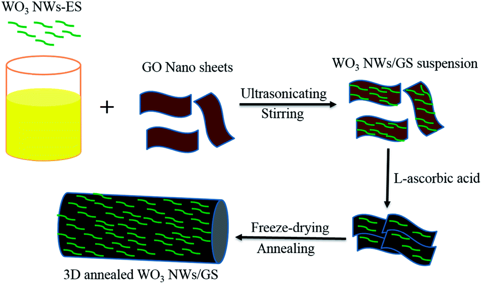 | ||
| Scheme 1 Schematic illustration of the preparation of the 3D annealed WO3 NWs/GS foam. | ||
Fig. 1a presents the XRD patterns of GO, WO3 NWs, 3D WO3 NWs/GS foam, and 3D annealed WO3 NWs/GS foam samples. Graphene oxide exhibits a sharp (002) diffraction peak at around 10.94°. For the pure WO3, 3D WO3 NWs/GS foam, and 3D annealed WO3 NWs/GS foam, all samples show diffraction peaks at around 14.1°, 23.0°, 28.2°, and 36.6°, corresponding to the (100), (001), (200), and (201) crystalline planes, respectively. All of these peaks can be ascribed to the standard diffraction pattern of the pure hexagonal phase of WO3 (JCPDS card no. 01-075-2187). After chemical reduction by L-ascorbic acid, the peaks at 10.94° for the 3D WO3 NWs/GS foam and 3D annealed WO3 NWs/GS foam samples disappear, indicating the reduction of GO to rGO. However, no typical peaks of graphene are detected, owing to the relatively low diffraction intensity of graphene.42 The most intense (001) peak in the diffraction pattern of the 3D annealed WO3 NWs/GS foam is shifted to a higher angle and its lattice parameter is changed from that of pure WO3 NWs because of the interaction between some oxygen groups of WO3 and graphene nanosheets.52 The interaction between WO3 NWs and the GS was confirmed using Raman spectral analysis. Fig. 1b shows the Raman spectra of the GO, 3D WO3 NWs/GS foam, and 3D annealed WO3 NWs/GS foam. For the bare GO, the G band is located at 1591 cm−1, whereas for the 3D annealed WO3 NWs/GS foam, the G band shifts to 1578 cm−1. The G-band position of graphene in the 3D annealed WO3 NWs/GS foam is approximately 13 cm−1 lower than that of the GO, which provides reliable evidence of the superior interactions between WO3 NWs and the GS as a composite rather than simple physical adherence of WO3 NWs on the GS surface.42 The D bands of the GO and 3D annealed WO3 NWs/GS foam are located at 1345 cm−1 and 1338 cm−1, respectively. The ID/IG ratio of graphene in the 3D annealed WO3 NWs/GS foam sample (ID/IG = 1.32) is higher than that in GO (ID/IG = 0.91), indicating that the incorporation of WO3 into the graphene structure increases the degree of disorder.43 For the 3D annealed WO3 NWs/GS foam sample, a set of Raman peaks in the range of 100–900 cm−1 can be observed along with the graphene peaks, which originate from the Raman shift modes of the WO3 component. The two bands located at 132 and 250 cm−1 correspond to the bending modes, and the bands located at 694 and 802 cm−1 can be ascribed to the stretching vibrations of the O–W–O and W–O–C bonds. Compared with that of the pure WO3 NWs (Fig. S1, ESI†), the peak at 700 cm−1, which is attributed to WO bonds, shifts to 694 cm−1 for the 3D annealed WO3 NWs/GS foam, probably because the W–O–C bonds make the initial WO bonds weaker.39
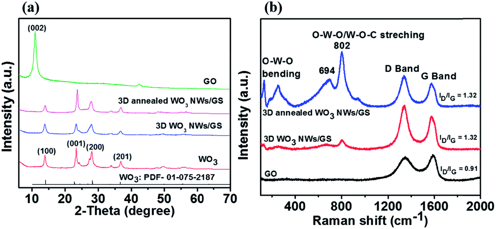 | ||
| Fig. 1 (a) XRD patterns and (b) Raman spectra of the GO, WO3 NWs, 3D WO3 NWs/GS foam, and 3D annealed WO3 NWs/GS foam. | ||
Fig. 2 presents the FESEM images of the GO, WO3 NWs, 3D WO3 NWs/GS foam, and 3D annealed WO3 NWs/GS foam. GO exhibits flake-like layers, in which the nanosheets are stacked on each other (Fig. 2a). The WO3 NWs exhibit agglomeration (Fig. 2b). For the 3D WO3 NWs/GS foam and 3D annealed WO3 NWs/GS foam, a 3D network structure with interconnected pores ranging from several nanometers to several micrometers is revealed (Fig. 2c and d). Moreover, in the case of the 3D annealed WO3 NWs/GS foam, the WO3 nanowires are homogeneously dispersed on the surface of the GS without apparent agglomeration (Fig. S2†). The EDX analysis detected W, O, and C elements in the sample (Fig. S3†).
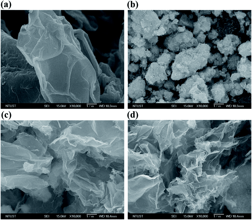 | ||
| Fig. 2 FE-SEM images of the (a) GO, (b) WO3 NWs, (c) 3D WO3 NWs/GS foam, and (d) 3D annealed WO3 NWs/GS foam. | ||
TEM analysis was performed to further investigate the morphology and structure of the 3D annealed WO3 NWs/GS foam (Fig. 3). From the TEM image of the GO (Fig. S4a†), the layered structure of the crumpled nanosheets can be clearly observed. The TEM image of the bare WO3 NWs reveals agglomerated nanowires (Fig. S4b†). For the 3D WO3 NWs/GS foam (Fig. S4c†), the WO3 nanowires are not well distributed on the GS surface. However, for the 3D annealed WO3 NWs/GS foam, WO3 nanowires with diameters of 5–8 nm are homogeneously dispersed on the surface of a continuous 3D porous network consisting of an ultrathin crumpled GS (Fig. 3a). This result is consistent with the SEM image observations. Fig. 3b shows a high-resolution TEM image of the 3D annealed WO3 NWs/GS foam and provides direct evidence of WO3 nanowires on the surface of the GS. As can be seen in the inset digital micrograph, the estimated interplanar spacing between the lattice fringes is 0.389 nm, corresponding to the d-spacing of the (001) plane of a hexagonal WO3 structure and is consistent with the XRD result. The HAADF-STEM images of the 3D annealed WO3 NWs/GS foam and the corresponding elemental mapping (Fig. 3c–f) clearly confirm that the constituent elements W, O, and C are distributed uniformly in the sample area and show a well-defined compositional profile of the composite, suggesting uniform decoration of WO3 NWs on the GS surface.
 | ||
| Fig. 3 (a) and (b) TEM images of the 3D annealed WO3 NWs/GS foam, (c) the HAADF-STEM image of the 3D annealed WO3 NWs/GS foam, and EDX elemental mapping results for (d) carbon, (e) oxygen, and (f) tungsten. | ||
The XPS spectra are shown in Fig. 4. The wide scan spectrum of the 3D annealed WO3 NWs/GS foam (Fig. 4a) shows the coexistence of W 4f, C 1s, and O 1s, in which the atomic contents of W, C, and O are 1.61%, 90.90%, and 7.49%, respectively. In the narrow scan W 4f XPS spectra of both the 3D WO3 NWs/GS foam (Fig. 4b) and 3D annealed WO3 NWs/GS foam (Fig. 4c), the peaks centered at 35.98 and 37.98 eV are attributed to the spin–orbit doublet of W 4f7/2 and W 4f5/2, respectively. In both cases, the peaks are well separated without shoulders, which indicates that the oxidation state of all W atoms in the form of WO3 is +6 on the surface of the GS.27 As shown in Fig. 4d, the O 1s core level peak of the 3D WO3 NWs/GS foam can be deconvoluted into two components at binding energies of approximately 530.9 eV, corresponding to W–O and/or CO bonds, and 532.7 eV, corresponding to C–OH and/or C–O–C groups. On the other hand, the O 1s core level peak of the 3D annealed WO3 NWs/GS foam (Fig. 4e) can be deconvoluted into three components at binding energies of approximately 530.8, 532.0, and 533.6 eV, corresponding to W–O and/or CO bonds, W–O–C bonds, and C–OH and/or C–O–C groups, respectively. Evidently, the annealing treatment induces the formation of new W–O–C bonds, confirming that the WO3 NWs are strongly attached to the GS, which is key to the synergistic effect that enhances the electrochemical activity.49,53 Moreover, the intensities of the O 1s peaks associated with CO bonds and C–OH and/or C–O–C groups in the 3D annealed WO3 NWs/GS foam are much lower than those of the peaks at binding energies of 532.4 and 533.3 eV in the O 1s XPS spectrum of the GO (Fig. S5†), indicating that in the case of the 3D annealed WO3 NWs/GS foam, the oxygen-containing functional groups on graphene have been substituted by W ions in WO3, forming new W–O–C bonds.53 The content of WO3 in the 3D annealed WO3 NWs/GS foam was determined using TGA, as shown in Fig. 4f. It shows that 38 wt% of weight loss occurs at temperatures from 550 to 700 °C, which can be attributed to the combustion of the graphene. Given the weight of the remaining product after the TGA measurement, the content of WO3 in the composite is approximately 62 wt%.
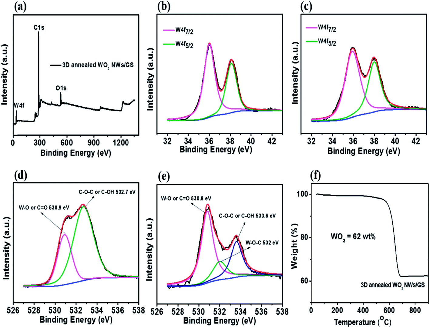 | ||
| Fig. 4 (a) Full-scan XP survey spectrum, narrow-scan XPS of (c) W 4f and (e) O 1s for the 3D annealed WO3 NWs/GS foam and (b) W 4f and (d) O 1s for the 3D WO3 NWs/GS foam, and (f) TGA curves of the 3D annealed WO3 NWs/GS foam. | ||
The Brunauer–Emmett–Teller (BET) specific surface area and porous nature of the as-prepared materials were investigated for all samples using nitrogen adsorption–desorption measurements (Fig. S6†). For all samples, the isotherms exhibit mesopores in their structures and the pore size distribution lies in the 2–100 nm range (Fig. S5,† inset). The calculated BET specific surface areas of the GO, WO3 NWs, 3D WO3 NWs/GS foam, and 3D annealed WO3 NWs/GS foam are 14.94, 80.80, 55.20, and 46.47 m2 g−1, respectively. The value for the 3D annealed WO3 NWs/GS foam is lower than those of the WO3 NWs and 3D WO3 NWs/GS foam, possibly due to the effect of heat treatment on the surface area of the 3D architecture.54,55 Moreover, the corresponding Barrett–Joyner–Halenda (BJH) calculations reveal a pore volume of 0.20 cm3 g−1 for the 3D WO3 NWs/GS foam and 0.22 cm3 g−1 for the 3D annealed WO3 NWs/GS foam. The designed 3D structure has high porosity, which can provide more surface electroactive sites and thus improve electrochemical performance.
Fig. 5 presents the CV curves of the GO, WO3 NWs, 3D WO3 NWs/GS foam, and 3D annealed WO3 NWs/GS foam in 1.6 M VOSO4 and 2.5 M H2SO4 electrolytes at a scan rate of 50 mV s−1. As shown in Fig. 5, all curves exhibit four main peaks and the corresponding redox couples are marked V2+/V3+ and VO2+/VO2+. The peak potential separation for each redox couple is an indication of the kinetics and reversibility of the redox reaction. For the 3D annealed WO3 NWs/GS foam, the anodic and cathodic peak potential separations (ΔEp) corresponding to redox couples V2+/V3+ and VO2+/VO2+ are 0.122 and 0.113 V, respectively, suggesting that the 3D annealed WO3 NWs/GS foam possesses relatively better electrochemical reversibility toward both V2+/V3+ and VO2+/VO2+ redox couples than the other samples. Moreover, the 3D annealed WO3 NWs/GS foam exhibits the highest anodic and cathodic peak current densities among all the tested samples on both the positive and negative sides, indicating that it has the most favorable electron transfer kinetics for both V2+/V3+ and VO2+/VO2+ redox reactions. The enhanced electrocatalytic activity of the composite material is caused by the strong interaction between WO3 NWs and the GS after annealing treatment.
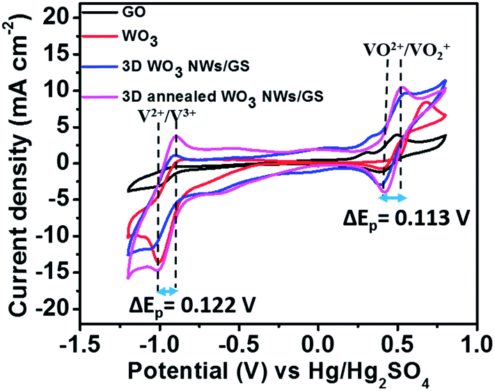 | ||
| Fig. 5 (A) CV curves of the GO, WO3 NW, 3D WO3 NWs/GS foam, and 3D annealed WO3 NWs/GS foam-modified GC electrodes in solutions of 1.6 M VOSO4 + 2.5 M H2SO4 at a scan rate of 50 mV s−1. | ||
Electrochemical impedance spectra (EIS) were recorded to further analyze the charge-transfer properties of the samples at applied potentials of 0.6 V (Fig. 6a) and −1.0 V (Fig. 6b). These applied potentials are associated with the redox reactions of VO2+/VO2+ and V2+/V3+, respectively. As shown in Fig. 6, the Nyquist plots contain a semicircular part in the high-frequency region and a linear part in the low-frequency region, indicating that the redox reactions are controlled by a combination of diffusion and charge transfer steps. The semicircular part can be attributed to the charge-transfer process occurring at the electrode/electrolyte interface, and the linear part is related to vanadium ion diffusion through the solution. The radius of the semicircle in the Nyquist plots is associated with the charge transfer resistance of the vanadium redox reaction, which is the fastest electron transfer reaction, implying that the smallest semicircle radius reflects the lowest charge transfer resistance.56Fig. 6a shows the Nyquist plots of the GO, WO3 NWs, 3D WO3 NWs/GS foam, and 3D annealed WO3 NWs/GS foam at a polarization potential of 0.6 V. The Nyquist plots of these samples can be fitted to an equivalent circuit (Fig. 6a, inset) and the obtained fitting results are shown in Table 1. In the equivalent circuit, Rs stands for the ohmic resistance, Rct stands for the charge-transfer resistance, CPE stands for the constant phase element that accounts for the double-layer capacitance of the solution/electrode interface, and W represents the Warburg impedance. The Rct values of the GO, WO3 NWs, 3D WO3 NWs/GS foam, and 3D annealed WO3 NWs/GS foam are 592.14, 174.60, 140.25, and 56.7 Ω, respectively. Fig. 6b shows the Nyquist plots of the samples at a polarization potential of −1.0 V. The Rct values of the GO, WO3 NWs, 3D WO3 NWs/GS foam, and 3D annealed WO3 NWs/GS foam are 335.95, 307.18, 271.18, and 72.32 Ω, respectively. At both polarization potentials, the 3D annealed WO3 NWs/GS foam showed the lowest Rct, indicating the best electrochemical catalytic activity for both the V2+/V3+ and VO2+/VO2+ redox couple reactions.
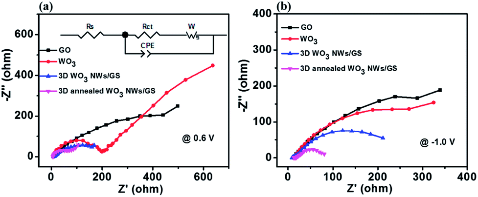 | ||
| Fig. 6 EIS curves of the GO, WO3 NW, 3D WO3 NWs/GS foam, and 3D annealed WO3 NWs/GS foam-modified GC electrodes in solutions of 1.6 M VOSO4 + 2.5 M H2SO4 at polarization potentials of (a) 0.6 V and (b) −1.0 V. | ||
| Electrode | R s (Ω) | R ct (Ω) | CPE (10−3 F sa−1) | W (Ω s−1/2) | a |
|---|---|---|---|---|---|
| GO | 8.09 | 592.14 | 2.97 | 51.16 | 0.59 |
| WO3 NWs | 7.56 | 174.60 | 0.017 | 125.40 | 0.89 |
| 3D WO3 NWs/GS foam | 9.97 | 140.25 | 6.27 | 2.00 | 0.55 |
| 3D annealed WO3 NWs/GS foam | 7.26 | 56.70 | 6.06 | 13.52 | 0.93 |
To further understand the practical efficiencies of the samples, a charge–discharge test was conducted on the VRFB single cell using the specific samples in both the electrodes. Fig. 7a presents the charge–discharge curves at a current density of 80 mA cm−2 for the cells with electrodes of pristine GF, GO-modified GF, WO3 NW-modified GF, 3D WO3 NWs/GS foam-modified GF, and 3D annealed WO3 NWs/GS foam-modified GF. The VRFB cell with the 3D annealed WO3 NWs/GS foam-modified GF electrode demonstrates a longer operation time, lower charge voltage, and higher discharge voltage than the other cells, resulting in a higher EE and VE. The efficiencies obtained from Fig. 7a are listed in Table 2. Notably, the 3D annealed WO3 NWs/GS foam-modified GF achieves the highest efficiencies among all the tested samples, and the corresponding CE, VE, and EE at a current density of 80 mA cm−2 are 94.98%, 83.69%, and 79.49%, respectively. This is because the annealing treatment induces the formation of new W–O–C bonds, confirming that the WO3 NWs are strongly attached to the GS, which is key to the synergistic effect that facilitates the redox reactions of the vanadium redox pairs and thereby enhances the electrochemical performance. Fig. 7b displays the charge–discharge profiles of the cell with 3D annealed WO3 NWs/GS foam-modified GF electrodes at current densities varied from 40 to 160 mA cm−2; the resulting efficiencies are summarized in Table 3. The percentage of CE increases slightly with increasing current density, which is attributed to the reduced time for the metal ion crossover through a Nafion 117 membrane that is caused by a decline in the charge–discharge time. However, both the EE and VE are lower because a rapid charge–discharge rate causes a substantial increase in the charge–discharge overpotential.6,57 As indicated in the table, even at a high current density of 160 mA cm−2, the VRFB assembled with 3D annealed WO3 NWs/GS foam-modified GF electrodes demonstrates good electrochemical performance, and the corresponding CE, VE, and EE are 98.18%, 68.85% and 67.60%, respectively, at a very high current density of 160 mA cm−2. Electrolyte utilization (left axis) and the corresponding charge–discharge capacity (right axis) of various samples are shown in Fig. S7(a).† In the fixed voltage region from 0.7 to 1.6 V at 80 mA cm−2, the cell assembled with the 3D annealed WO3 NWs/GS foam-modified GF as the electrode exhibits the highest discharge capacity (14.54 A h L−1, reaching 67.82% of the theoretical capacity) compared with those of cells assembled with pristine GF (5.31 A h L−1, 24.77% of the theoretical capacity) and the 3D WO3 NWs/GS foam without annealing treatment (11.70 A h L−1, 54.57% of the theoretical capacity). High vanadium electrolyte utilization is beneficial to improving the energy density and reducing the capital cost of the battery, because the cost of the electrolyte is nearly 40% of the total cost of the system.7 Furthermore, the discharge energy density is determined by both discharge capacity and voltage. As presented in Fig. S7(b),† the VRFB cell using the 3D annealed WO3 NWs/GS foam-modified GF electrode displays the largest discharge energy density (20.05 W h L−1) among all samples. Similarly, the charge capacity and charge energy density of the samples show the same trend. On the bases of these results, the VRFB cell using the 3D annealed WO3 NWs/GS foam-modified GF electrode can substantially improve the overall VRFB performance, in terms of key operation parameters such as EE, VE, electrolyte utilization, charge/discharge capacity, and charge/discharge energy density.
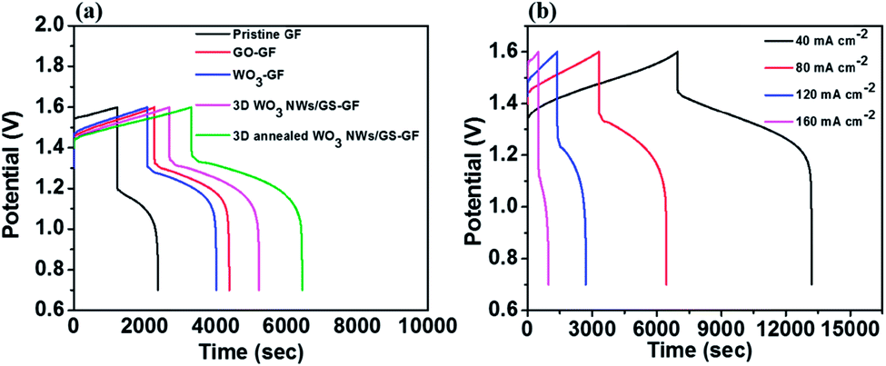 | ||
| Fig. 7 Charge–discharge curves of the (a) pristine GF, GO-modified GF, WO3 NW-modified GF, 3D WO3 NWs/GS foam-modified GF, and 3D annealed WO3 NWs/GS foam-modified GF at a current density of 80 mA cm−2 and (b) 3D annealed WO3 NWs/GS foam-modified GF at different current densities. | ||
| Cell with | CE (%) | VE (%) | EE (%) |
|---|---|---|---|
| Pristine GF | 93.70 | 71.23 | 66.74 |
| GO-modified GF | 92.74 | 80.35 | 74.52 |
| WO3 NW-modified GF | 94.06 | 78.47 | 73.81 |
| 3D WO3 NWs/GS foam-modified GF | 94.05 | 80.50 | 75.70 |
| 3D annealed WO3 NWs/GS foam-modified GF | 94.98 | 83.69 | 79.49 |
| Current density (mA cm−2) | CE (%) | VE (%) | EE (%) |
|---|---|---|---|
| 40 | 90.72 | 92.29 | 83.73 |
| 80 | 94.98 | 83.69 | 79.49 |
| 120 | 96.24 | 75.86 | 73.01 |
| 160 | 98.18 | 68.85 | 67.60 |
Fig. 8 presents the efficiencies after 50 cycles at 80 mA cm−2 to further examine the stability of the samples. The average coulombic efficiencies of the cells assembled with pristine GF, 3D WO3 NWs/GS foam-modified GF, and 3D annealed WO3 NWs/GS foam-modified GF are nearly similar (Fig. 8a). This indicates that the general effects of self-discharge on each electrode are similar.58 However, the average voltage efficiency (Fig. 8b) and energy efficiency (Fig. 8c) of the cell with the 3D annealed WO3 NWs/GS foam-modified GF electrode are much higher than those of the cells with pristine graphite felt and 3D WO3 NWs/GS foam-modified GF electrodes. The cycle life test results reveal no obvious decay in efficiency even after 50 cycles, indicating the high stability of the 3D annealed WO3 NWs/GS foam-modified GF electrode in an acidic vanadium electrolyte during long-term cycling.
 | ||
| Fig. 8 The (a) coulombic efficiency, (b) voltage efficiency, and (c) energy efficiency estimated from 50 charge–discharge cycles of the cells with pristine GF, 3D WO3 NWs/GS foam-modified GF, and 3D annealed WO3 NWs/GS foam-modified GF at 80 mA cm−2. | ||
The excellent performance of the 3D annealed WO3 NWs/GS foam can be attributed to the following causes. (1) The annealing treatment induces the formation of new W–O–C bonds, confirming that the WO3 NWs are anchored strongly to the GS, which facilitates the charge transfer of the redox reactions and improves the stability of the electrode. (2) The 3D annealed WO3 NWs/GS foam exhibits a 3D hierarchical porous structure, which can provide more surface electroactive sites to improve the electrochemical performance of the VRFB. (3) The WO3 nanowires are homogeneously dispersed on the surface of the GS without apparent agglomeration. Thus, the EE of the VRFB cell using the 3D annealed WO3 NWs/GS foam-modified GF electrode is substantially enhanced by improving the electrochemical conversion of the electroactive components.
To further evaluate the electrocatalytic properties of the synthesized catalyst for VRFBs, we have summarized several related studies for comparison (Table S1†). The VRFB cell using the 3D annealed WO3 NWs/GS foam for modifying a GF electrode has an EE of 67.6% at a high current density of 160 mA cm−2, which is superior to those achieved by previously reported VRFBs using GF electrodes modified by other electrocatalysts.
Conclusions
In summary, a 3D annealed WO3 NWs/GS foam to be used as an electrocatalyst for VRFBs has been successfully synthesized through an in situ self-assembly of graphene prepared by mild chemical reduction. We investigated the effect of annealing and found that it can substantially enhance the chemical interaction between the WO3 NWs and the GS by forming new W–O–C bonds; this is key to the synergistic effect that facilitates the redox reactions of the vanadium redox pairs. Moreover, the 3D annealed WO3 NWs/GS foam exhibits a 3D hierarchical porous structure, which can provide more surface electroactive sites to improve the electrochemical performance of VRFBs. As a result, the 3D annealed WO3 NWs/GS foam exhibits the highest reversibility and electrocatalytic activity toward the V2+/V3+ and VO2+/VO2+ redox couples among all the tested samples. Consequently, the VRFB cell using the 3D annealed WO3 NWs/GS foam-modified graphite felt electrode demonstrates an outstanding EE of 79.49% at a current density of 80 mA cm−2. This EE exceeds those of cells assembled with pristine GF (by 12.75%) and 3D WO3 NWs/GS foam-modified GF electrodes (by 3.79%). Cycle life test results reveal no obvious decay in efficiency even after 50 cycles, indicating the high stability of the 3D annealed WO3 NWs/GS foam-modified GF electrode in an acidic vanadium electrolyte during long-term cycling.Experimental
Synthesis of the WO3 NW suspension
In this experiment, all reagents used were of analytical purity and used as purchased without further purification. To synthesize WO3 NWs, 2 g of Na2WO4·2H2O was dissolved in deionized water (45 mL) at ambient temperature under magnetic stirring. 5 mL of HCl solution (3 M) was then added drop by drop to form a solution of H2WO4 under uninterrupted stirring. Following this, 30 mL of ammonium sulfate [(NH4)2SO4] solution (0.5 M) was added, and a homogenous solution was obtained after continuous stirring for 30 min. Next, the resulting solution was transferred to a Teflon-lined stainless steel autoclave with a 120 mL capacity. The reaction vessel was finally sealed and heated at 180 °C in a muffle furnace for 24 h to subject it to hydrothermal treatment. After naturally cooling to room temperature, the resulting yellow precipitate was collected by centrifugation, washed several times with distilled water, and dried overnight in an oven at 60 °C. The WO3 NW powder was then dispersed in 100 mL of ethanol to form a homogeneous WO3 NWs-ES suspension.Synthesis of the 3D annealed WO3 NWs/GS foam
WO3 NWs-ES (15 mL, 10 mg mL−1) was added into a commercial graphene oxide (GO) dispersion (50 mL, 2.5 mg mL−1) in conjunction with stirring. After continuously stirring for 3 h, followed by ultrasonication for 1 h, 250 mg of L-ascorbic acid was added into the mixed suspension. The mixed suspension was transferred to a Teflon-lined stainless steel autoclave and kept in a muffle furnace for 8 h at 75 °C to reduce the GO and induce the self-assembly process, thereby obtaining a 3D WO3 NWs/GS monolith. Subsequently, the monolith was taken out of the autoclave, washed repeatedly with distilled water for 2 days, and freeze-dried into a 3D WO3 NWs/GS foam. Finally, the 3D annealed WO3 NWs/GS foam was obtained after calcination at 550 °C for 2 h under an argon atmosphere.Structural characterization
The crystalline phase of the samples was identified using a D2 phaser XRD diffractometer equipped with a Cu Kα (λ = 1.54056 Å) radiation source operating at 10 mA and 30 kV. The morphologies of the samples were determined by field-emission scanning electron microscopy (JEOL, JSM 6500F, SEM) and transmission electron microscopy (TEM) using a JEOL-2100 model combined with energy-dispersive X-ray spectroscopy (EDX). Raman spectroscopy (iHR550) was employed to validate the graphene materials in the hybrid. The chemical compositions of the catalysts were examined using X-ray photoelectron spectroscopy (Thermal K-Alpha, XPS) analysis. Thermogravimetric analysis (TGA) was conducted using a TA instrument (Q5000 IR Thermogravimetric Analyzer) at a heating rate of 10 °C min−1 in air from 40 °C to 900 °C. The Brunauer–Emmett–Teller (BET) surface area of the as-synthesized sample was determined using a surface area and porosity analyzer instrument (Micrometry, ASAP 2420).Electrochemical measurements
Electrochemical measurements were conducted in a three-electrode cell. The standard Hg/Hg2SO4/sat. K2SO4 was used as the reference electrode and a Pt wire was used as the counter electrode. The working electrode was a rotating ring-disk electrode (RRDE, PINE AFE7R9GCPT) consisting of a glassy carbon (GC) disk and a platinum ring with a geometric surface area of 0.237 cm2. The electrocatalyst ink was prepared by dispersing 7.5 mg of the desired electrocatalyst in a mixture of 2.8 mL of deionized water and 0.2 mL of 5 wt% Nafion solution in an ultrasonic bath for 20 min. A total of 28.5 μL of the electrocatalyst ink was dropped onto the GC disk electrode with a micropipette and dried at room temperature in air. The loading mass of the active material on the GC disk electrode was 300 μg cm−2. All electrochemical measurements were performed using a Bio-Logic SP-240. Cyclic voltammetry (CV) was performed in 1.6 M VOSO4 in a 2.5 M solution of H2SO4 in the approximate potential range of −1.2 to 0.8 V versus Hg/Hg2SO4 at a scan rate of 50 mV s−1. The electrolyte was purged with N2 to avoid undesirable oxidation of the active species. Furthermore, electrochemical impedance spectroscopy (EIS) was carried out in the frequency range from 100 kHz to 10 mHz at an amplitude of 10 mV and applied potentials of −1.0 and 0.6 V.Electrode fabrication and VRFB charge–discharge tests
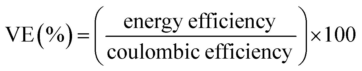
The performance of the VRFB with the fabricated electrodes was evaluated by charge−discharge experiments. A 3D annealed WO3 NWs/GS foam-modified GF electrode was fabricated by adding 20 mg of the sample to a mixture of 45 mL of ethanol and 5 mL of 5 wt% Nafion, and the mixture was then ultrasonicated for 1 h to obtain a completely dispersed suspension. Subsequently, 2 mg cm−2 of electrocatalyst ink was coated onto the pristine GF to serve as the activation layer of the active electrode, and dried at 60 °C for 6 h in a vacuum oven. The other electrodes were fabricated according to a similar process. The areas of the modified electrodes at both the negative and positive sides were 25 cm2 (5 cm × 5 cm). Pristine Nafion 117 was used as a membrane separator. The single flow cell was linked to glass reservoirs containing the same volume electrolyte (60 mL) of 1.6 M VOSO4 in a 2.5 M H2SO4 solution on each side. The electrolyte flow rate for each half-cell was 30 mL min−1. The VRFB flow cell measurement was performed using a Bio-Logic SP-240 at various current densities in the potential range from 1.6 to 0.7 V.The energy efficiency (EE), coulombic efficiency (CE), and voltage efficiency (VE) of the battery are estimated from charge–discharge cycles as follows:
 | (3) |
 | (4) |
 | (5) |
Conflicts of interest
There are no conflicts to declare.Acknowledgements
This research is supported by the Institute of Nuclear Energy Research, Atomic Energy Council. We would like to acknowledge Prof. Kuei-Hsien Chen of Academia Sinica and Prof. Li-Chyong Chen of National Taiwan University (NTU) for their helpful assistance.Notes and references
- P. Leung, X. Li, C. Ponce de León, L. Berlouis, C. T. J. Low and F. C. Walsh, RSC Adv., 2012, 2, 10125 RSC.
- R. M. Darling, K. G. Gallagher, J. A. Kowalski, S. Ha and F. R. Brushett, Energy Environ. Sci., 2014, 7, 3459–3477 CAS.
- J. Lee, A. Tolosa, B. Krüner, N. Jäckel, S. Fleischmann, M. Zeiger, D. Kim and V. Presser, Sustainable Energy Fuels, 2017, 1, 299–307 Search PubMed.
- B. Huskinson, M. P. Marshak, C. Suh, S. Er, M. R. Gerhardt, C. J. Galvin, X. Chen, A. Aspuru-Guzik, R. G. Gordon and M. J. Aziz, Nature, 2014, 505, 195–198 CrossRef CAS PubMed.
- K. J. Kim, M.-S. Park, Y.-J. Kim, J. H. Kim, S. X. Dou and M. Skyllas-Kazacos, J. Mater. Chem. A, 2015, 3, 16913–16933 CAS.
- B. Li, M. Gu, Z. Nie, Y. Shao, Q. Luo, X. Wei, X. Li, J. Xiao, C. Wang, V. Sprenkle and W. Wang, Nano Lett., 2013, 13, 1330–1335 CrossRef CAS PubMed.
- B. Li, M. Gu, Z. Nie, X. Wei, C. Wang, V. Sprenkle and W. Wang, Nano Lett., 2014, 14, 158–165 CrossRef CAS PubMed.
- Y. Huang, Q. Deng, X. Wu and S. Wang, Int. J. Hydrogen Energy, 2017, 42, 7177–7185 CrossRef CAS.
- Z. He, Z. Chen, W. Meng, Y. Jiang, G. Cheng, L. Dai and L. Wang, J. Energy Chem., 2016, 25, 720–725 CrossRef.
- G. Wei, Z. Gao, Z. Wei, X. Fan, J. Liu and C. Yan, Phys. Chem. Chem. Phys., 2015, 17, 20368–20375 RSC.
- S. Jeong, S. An, J. Jeong, J. Lee and Y. Kwon, J. Power Sources, 2015, 278, 245–254 CrossRef CAS.
- Z. Jiang, K. Klyukin and V. Alexandrov, Phys. Chem. Chem. Phys., 2017, 19, 14897–14901 RSC.
- K. J. Kim, H. S. Lee, J. Kim, M. S. Park, J. H. Kim, Y. J. Kim and M. Skyllas-Kazacos, ChemSusChem, 2016, 9, 1329–1338 CrossRef CAS PubMed.
- M. Park, J. Ryu, Y. Kim and J. Cho, Energy Environ. Sci., 2014, 7, 3727–3735 CAS.
- H. Zhou, Y. Shen, J. Xi, X. Qiu and L. Chen, ACS Appl. Mater. Interfaces, 2016, 8, 15369–15378 CAS.
- S. Wang, X. Zhao, T. Cochell and A. Manthiram, J. Phys. Chem. Lett., 2012, 3, 2164–2167 CrossRef CAS PubMed.
- H. J. Lee and H. Kim, J. Electrochem. Soc., 2015, 162, A1675–A1681 CrossRef CAS.
- K. J. Kim, M. S. Park, J. H. Kim, U. Hwang, N. J. Lee, G. Jeong and Y. J. Kim, Chem. Commun., 2012, 48, 5455–5457 RSC.
- R. H. Huang, C. H. Sun, T. M. Tseng, W. K. Chao, K. L. Hsueh and F. S. Shieu, J. Electrochem. Soc., 2012, 159, A1579–A1586 CrossRef CAS.
- B. Sun and M. Sykllas-Kazacos, Electrochim. Acta, 1992, 37, 2459–2465 CrossRef CAS.
- B. Sun and M. Sykllas-Kazacos, Electrochim. Acta, 1992, 37, 1253–1260 CrossRef CAS.
- W. Zhang, J. Xi, Z. Li, H. Zhou, L. Liu, Z. Wu and X. Qiu, Electrochim. Acta, 2013, 89, 429–435 CrossRef CAS.
- Z. He, L. Shi, J. Shen, Z. He and S. Liu, Int. J. Energy Res., 2015, 39, 709–716 CrossRef CAS.
- X. Wu, H. Xu, P. Xu, Y. Shen, L. Lu, J. Shi, J. Fu and H. Zhao, J. Power Sources, 2014, 263, 104–109 CrossRef CAS.
- Z. He, Y. Jiang, H. Zhou, G. Cheng, W. Meng, L. Wang and L. Dai, Int. J. Energy Res., 2017, 41, 439–447 CrossRef CAS.
- I. Mustafa, I. Lopez, H. Younes, R. A. Susantyoko, R. A. Al-Rub and S. Almheiri, Electrochim. Acta, 2017, 230, 222–235 CrossRef CAS.
- D. M. Kabtamu, J.-Y. Chen, Y.-C. Chang and C.-H. Wang, J. Mater. Chem. A, 2016, 4, 11472–11480 CAS.
- X. Wu, H. Xu, L. Lu, H. Zhao, J. Fu, Y. Shen, P. Xu and Y. Dong, J. Power Sources, 2014, 250, 274–278 CrossRef CAS.
- H. Zhou, J. Xi, Z. Li, Z. Zhang, L. Yu, L. Liu, X. Qiu and L. Chen, RSC Adv., 2014, 4, 61912–61918 RSC.
- H. T. Thu Pham, C. Jo, J. Lee and Y. Kwon, RSC Adv., 2016, 6, 17574–17582 RSC.
- Y. Shen, H. Xu, P. Xu, X. Wu, Y. Dong and L. Lu, Electrochim. Acta, 2014, 132, 37–41 CrossRef CAS.
- T. M. Tseng, R. H. Huang, C. Y. Huang, C. C. Liu, K. L. Hsueh and F. S. Shieu, J. Electrochem. Soc., 2014, 161, A1132–A1138 CrossRef CAS.
- S. Salmaoui, F. Sediri, N. Gharbi, C. Perruchot, S. Aeiyach, I. A. Rutkowska, P. J. Kulesza and M. Jouini, Appl. Surf. Sci., 2011, 257, 8223–8229 CrossRef CAS.
- J. Su, X. Feng, J. D. Sloppy, L. Guo and C. A. Grimes, Nano Lett., 2011, 11, 203–208 CrossRef CAS PubMed.
- H. Wu, M. Xu, P. Da, W. Li, D. Jia and G. Zheng, Phys. Chem. Chem. Phys., 2013, 15, 16138–16142 RSC.
- X. Li, W. Mu, X. Xie, B. Liu, H. Tang, G. Zhou, H. Wei, Y. Jian and S. Luo, J. Hazard. Mater., 2014, 264, 386–394 CrossRef CAS PubMed.
- X. Li, S. Yang, J. Sun, P. He, X. Xu and G. Ding, Carbon, 2014, 78, 38–48 CrossRef CAS.
- M. Zhang, Y. Wang and M. Jia, Electrochim. Acta, 2014, 129, 425–432 CrossRef CAS.
- R. Azimirad and S. Safa, Mater. Chem. Phys., 2015, 162, 686–691 CrossRef CAS.
- Z. González, C. Flox, C. Blanco, M. Granda, J. R. Morante, R. Menéndez and R. Santamaría, J. Power Sources, 2017, 338, 155–162 CrossRef.
- Y. Xu, K. Sheng, C. Li and G. Shi, ACS Nano, 2010, 4, 4324–4330 CrossRef CAS PubMed.
- H. Huang, Z. Yue, G. Li, X. Wang, J. Huang, Y. Du and P. Yang, J. Mater. Chem. A, 2013, 1, 15110 CAS.
- A. Ejigu, M. Edwards and D. A. Walsh, ACS Catal., 2015, 5, 7122–7130 CrossRef CAS.
- S. Srivastava, K. Jain, V. N. Singh, S. Singh, N. Vijayan, N. Dilawar, G. Gupta and T. D. Senguttuvan, Nanotechnology, 2012, 23, 205501 CrossRef PubMed.
- S. Nardecchia, D. Carriazo, M. L. Ferrer, M. C. Gutierrez and F. del Monte, Chem. Soc. Rev., 2013, 42, 794–830 RSC.
- W. Chen and L. Yan, Nanoscale, 2011, 3, 3132–3137 RSC.
- X. Zhang, Z. Sui, B. Xu, S. Yue, Y. Luo, W. Zhan and B. Liu, J. Mater. Chem., 2011, 21, 6494 RSC.
- J. S. Lee, H. J. Ahn, J. C. Yoon and J. H. Jang, Phys. Chem. Chem. Phys., 2012, 14, 7938–7943 RSC.
- R. Tian, Y. Zhang, Z. Chen, H. Duan, B. Xu, Y. Guo, H. Kang, H. Li and H. Liu, Sci. Rep., 2016, 6, 19195 CrossRef CAS PubMed.
- R. Wang, C. Xu, J. Sun, L. Gao and H. Yao, ACS Appl. Mater. Interfaces, 2014, 6, 3427–3436 CAS.
- S. Li, X. Cao, C. N. Schmidt, Q. Xu, E. Uchaker, Y. Pei and G. Cao, J. Mater. Chem. A, 2016, 4, 4242–4251 CAS.
- M. E. Khan, M. M. Khan and M. H. Cho, RSC Adv., 2016, 6, 20824–20833 RSC.
- S. Yang, X. Song, P. Zhang, J. Sun and L. Gao, Small, 2014, 10, 2270–2279 CrossRef CAS PubMed.
- W. Chen, S. Li, C. Chen and L. Yan, Adv. Mater., 2011, 23, 5679–5683 CrossRef CAS PubMed.
- W. Feng, G. Wu and G. Gao, J. Mater. Chem. A, 2014, 2, 585–590 CAS.
- D. M. Kabtamu, J.-Y. Chen, Y.-C. Chang and C.-H. Wang, J. Power Sources, 2017, 341, 270–279 CrossRef CAS.
- B. Jiang, L. Wu, L. Yu, X. Qiu and J. Xi, J. Membr. Sci., 2016, 510, 18–26 CrossRef CAS.
- Z. He, L. Liu, C. Gao, Z. Zhou, X. Liang, Y. Lei, Z. He and S. Liu, RSC Adv., 2013, 3, 19774 RSC.
Footnote |
| † Electronic supplementary information (ESI) available. See DOI: 10.1039/c7se00271h |
| This journal is © The Royal Society of Chemistry 2017 |