Visible-light-absorbing semiconductor/molecular catalyst hybrid photoelectrodes for H2 or O2 evolution: recent advances and challenges
Mei
Wang
 *a,
Yong
Yang
a,
Junyu
Shen
a,
Jian
Jiang
a and
Licheng
Sun
 ab
ab
aState Key Laboratory of Fine Chemicals, DUT-KTH Joint Education and Research Center on Molecular Devices, Dalian University of Technology (DUT), Dalian 116024, China. E-mail: symbueno@dlut.edu.cn
bDepartment of Chemistry, KTH Royal Institute of Technology, Stockholm 10044, Sweden
First published on 12th June 2017
Abstract
The research on the conversion of solar energy and its storage as an eco-friendly and momentarily available chemical fuel, such as H2, by sunlight-driven water splitting is closely related to the sustainable development of the global economy and to the continuous improvement of the modern living standards of human beings. One of the most promising approaches to sunlight-driven water splitting is to construct a dual-illuminated photoelectrochemical (PEC) cell by integrating a photoanode with a photocathode in a tandem configuration. To this end, the important work is to individually develop highly efficient, durable, inexpensive, and readily scalable photoanodes and photocathodes for each half reaction of water splitting, either O2 or H2 evolution reaction (OER or HER). A promising approach emerging in recent years towards OER photoanodes and HER photocathodes is the immobilization of molecular catalysts (MC) onto the surface of visible-light-absorbing semiconductor (VLASC) electrodes. Very recently, some encouraging results have been achieved in the construction of MC-modified VLASC photoanodes and photocathodes. This review is focused on the recent advances in hybrid photoelectrodes for OER and HER, which were built by the integration of MCs with VLASC materials. After a brief introduction of three major units, viz. VLASC materials, MCs, and anchor groups, used to date for fabricating hybrid photoelectrodes for OER and HER, the construction strategy and the performance of the VLASC/MC photoanodes and photocathodes are described in two respective chapters. Finally, challenges and developments in future studies of VLASC/MC hybrid photoelectrodes are discussed.
1 Introduction
The conversion of solar energy into an eco-friendly and momentarily available chemical fuel, in the form of H–H bonds, by sunlight-driven water splitting, and subsequent storage are great aspirations of chemists.1,2 Over several decades, substantial progress and some breakthroughs have been achieved, especially in recent years, in developing efficient, durable, and cheap photocatalytic systems and devices for solar-to-hydrogen (STH) conversion, thanks to the persistent efforts of a great number of research groups around the world. In general, three technological approaches have been developed for effective light-driven overall water splitting: (i) connecting photovoltaic modules with discrete electrolyzers to build a PV/electrolyzer apparatus;3–5 (ii) integrating a photoanode with a cathode or a photocathode in a tandem configuration to construct a photoelectrochemical (PEC) cell;6–8 (iii) assembling a broad band semiconductor material (SCM) with water oxidation catalyst (WOC) and/or water reduction catalyst (WRC) to form a one-pot photocatalyst colloid system.9,10 Several perspectives and tutorial reviews have commented on the advantages and drawbacks of different device designs.11–14 Among these three approaches, the integrated PEC cell, an optimum design compromise of a PV/electrolyzer apparatus and a one-pot photocatalyst colloid system, is a most promising approach to large-scale H2 production from the perspective of the STH conversion efficiency, cost, safety, and availability.15PEC water splitting technology allows the harvesting of sunlight and the electrolysis of water to occur simultaneously in a single device in an aqueous electrolyte. In general terms, a PEC cell can be constructed in two ways: by the integration of a photoanode and a photocathode to form a dual-illuminated tandem PEC cell, or by the assembly of a photoactive electrode, either a photoanode or a photocathode, with a photo-inactive counter-electrode to build a single-illuminated PEC cell.16 Detailed categories and fundamental knowledge of PEC cells have been introduced by some tutorial papers.17–22 The single-illuminated PEC cell, which was first reported in 1972,23 required extra electrical energy for driving the water splitting reaction and therefore cannot provide high STH efficiency, due to the narrow absorption of sunlight by a single photoelectrode. Spontaneous water splitting PEC cells, i.e., without the need for bias, with a dual-illuminated tandem device design, have been demonstrated in the laboratory.24 Therefore, dual-illuminated PEC cells have become an attractive target for many researchers in current years.25–27 To build PEC cells with high STH efficiency, the integrated photoanode and photocathode should have well-matched tandem band energy levels, complementary light absorption properties, compatible H2- and O2-evolution rates, and similar durability in testing electrolytes. In the advanced stages towards this end, the important work is to individually develop highly efficient, durable, inexpensive, and readily scalable photoanodes and photocathodes for each half reaction of water splitting.
An electrocatalyst-modified photoelectrode for the half reaction of water splitting, either the O2 or H2 evolution reaction (OER or HER), functions in four steps as follows: the absorption of solar energy by a light absorber on the electrode, the charge separation in the light absorber, the charge transport from the light absorber to an electrocatalyst, and the occurrence of OER or HER at the surface of the electrode, driven by the photo-generated redox potential stored in the catalyst. Therefore, light absorbers and OER or HER electrocatalysts are two crucial components for fabricating effective photoanodes and photocathodes. According to the types of light absorbers and electrocatalysts, photoelectrodes can be categorized into all-inorganic electrodes (visible-light-absorbing semiconductor (VLASC)/inorganic material catalyst) and SC-molecular hybrid electrodes, including VLASC/molecular catalyst (MC), dye-sensitized SC/MC, and dye-sensitized SC/inorganic material catalyst. The OER photoanodes and HER photocathodes that were constructed by the combination of SCs or dye-sensitized SCs with inorganic material catalysts as well as the corresponding integrated PEC cells have been widely studied. The advances in this field have been summarized in some recent reviews and perspectives.28–31 The present review focuses on the recent advances in MC-modified hybrid photoelectrodes for OER and HER, built by the combination of MCs with VLASCs. The MC-based three-component hybrid systems containing either sacrificial electron acceptors or electron donors and the photoelectrodes made of organic dye- and organometallic chromophore-sensitized SCs will not be included in this review; the progress on these topics have been reviewed in several recently published papers.32–40 In this review, we first make a general introduction of three major components, viz. SCMs, MCs, and anchor units, used to date for fabricating VLASC/MC hybrid photoelectrodes for OER and HER, which is followed by a brief description of the strategies for immobilizing MCs onto the surface of SCMs. The recent advances in MC-modified hybrid photoanodes for OER and photocathodes for HER are presented, respectively, in subsequent two chapters. Photoelectrodes that were fabricated by using organometallic complexes as precursors to deposit inorganic WOCs or WRCs onto SC surfaces will not be included in these two chapters.41,42 In the last chapter, challenges and developments in future studies of MC-modified hybrid photoelectrodes are discussed.
2 Assembling of VLASC/MC hybrid photoelectrodes
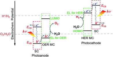
For fabricating eventually available hybrid photoanodes and photocathodes used for PEC cells (Fig. 1), molecular electrocatalysts with high activity at low overpotential for OER or HER and SCs with broad absorption in the solar spectrum, long excited state lifetime, and high charge carrier mobility are eagerly desired. Additionally, both of these components are expected to be inexpensive, eco-friendly, and robust under operating conditions. The intrinsic activity and stability of a hybrid photoelectrode depend predominantly on the properties of SCM and MC, which compose the photoelectrode. In addition to SCM and MC, the length, rigidity, orientation, and electronic properties of the linker between MC and SCM, as well as the type of anchor, also conspicuously influence the PEC performance of VLASC/MC hybrid photoelectrodes. To date, no photoelectrodes made for OER or HER satisfy all the requirements for practical application in a PEC cell for sunlight-driven overall water splitting at zero or low bias.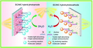 | ||
| Fig. 1 Schematic of a hybrid photoanode and photocathode constructed with elemental building units, VLASC, OER-MC or HER-MC, anchor, and linker. | ||
2.1 VLASC materials used for hybrid photoelectrodes
SCMs that are used as sole light absorbers (without sensitization) in photoelectrodes must feature a proper band gap and suitable energy positions of valence and conduction band edges. The SCMs with band gaps larger than 3.1 eV cannot absorb visible light, which accounts for more than 95% irradiation of the solar spectrum, while a narrow band gap will lead to small photovoltage in a photoelectrode under illumination. The energy position of the valence band (VB) upper edges of SCMs used for photoanodes must be more positive than the O2/H2O thermodynamic potential, while the position of the conduction band (CB) lower edges of SCMs used for photocathodes should be more negative than the H+/H2 thermodynamic potential. Even though some SCMs satisfy these stringent thermodynamic criteria, the poor kinetics for OER or HER at the surface of these materials constrains their photocatalytic efficiencies.43 Therefore, it is necessary to load the co-catalysts on the SC photoelectrodes to facilitate the OER and HER. Many solid material electrocatalysts for OER or HER have been loaded onto the surface of various SC photoelectrodes, and the advances in this topic have been documented in the literature.44–46 In the other aspect, organic dye- and organometallic chromophore-sensitized photoelectrodes have been widely studied over the past decade.32–40 Considering that SCMs generally have better photostability and broader spectral ranges in the solar spectrum than molecular dyes, the combination of MCs with inorganic visible-light-absorbing SCMs can be a promising approach to constructing hybrid photoelectrodes with higher activity and better stability, compared to dye-sensitized photoelectrodes. To date, the sorts of SCMs used for fabricating MC-modified SC hybrid photoelectrodes for OER and HER are still quite limited.Metal oxides, Fe2O3, WO3, and BiVO4, are the most commonly used visible-light-absorbing SCMs for fabricating hybrid photoanodes.47–51 The band gaps are about 2.2 eV for α-Fe2O3, 2.6 eV for WO3, and 2.4 eV for BiVO4 (Fig. 2),44,52 corresponding to optical absorption edges of about 560, 480, and 520 nm, respectively, for these materials. The VB upper edges of these metal oxides are more positive than the thermodynamic potential for OER by nearly a volt or greater, while the energy positions of their CB lower edges are less negative than the thermodynamic potential for HER. On the basis of the VB and CB energy positions and the band gaps of these metal oxides, they are suitable for making OER photoanodes. It should be noticed that Fe2O3 and BiVO4 offer good stability in basic and neutral electrolytes, while WO3, unlike most metal oxides, has good stability towards corrosion in acidic electrolytes, which is a preferred condition for HER. When designing a hybrid photoelectrode, one should consider not only the proper alignment of the band edges of SCMs and the Frontier orbitals of MCs, but also the compatible stability of these two components in contact with electrolytes.
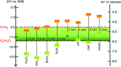 | ||
| Fig. 2 Band gaps and band positions for the SCMs mentioned in this review, in vacuum or in an aqueous electrolyte at pH 0. | ||
In addition to metal oxides, Ta3N5 and n-type Si are also modified by MCs to fabricate hybrid photoanodes. Tantalum nitride (Ta3N5) has a band gap of 2.06 eV with VB and CB energy positions straddling the O2/H2O and H+/H2 thermodynamic potentials.53,54 The oxidative corrosion at the surface under photolysis conditions is a fatal shortness for photoanodes made of Ta3N5 and n-type Si, which are therefore usually covered with a thin TiO2 protective layer to improve the stability of such photoelectrodes.55
The sorts of VLASCs for constructing hybrid photocathodes are even less than those for photoanodes. Only p-type Si, In- and/or Ga-containing SCMs have been used for VLASC/MC hybrid photocathodes (Fig. 2). Silicon with a narrow band gap of 1.12 eV can capture photons in a significant portion of the solar spectrum.56 Although the CB lower edge of p-Si is a few hundred millivolts more negative than the H+/H2 thermodynamic potential, the pristine p-Si is almost inactive for HER under illumination, due to the sluggish charge-transfer kinetics at the Si/electrolyte interface. Several recently reported examples have proved that the modification of the surface of a Si photocathode by molecular electrocatalysts, in addition to widely studied solid material electrocatalysts, can effectively improve the HER kinetics at the Si electrode/electrolyte interface. To overcome the oxidative corrosion problem of Si-based photocathodes, the most commonly used strategy is to decorate a TiO2 thin layer on the surface of Si electrodes by atomic layer deposition (ALD).57–60 Such a layer not only protects the surface of Si material from corrosion, but also provides available hydroxyl groups for grafting MCs on the electrode surface. SCs of group III, InP, GaP, and GaInP2, have desirable band gaps, viz. 1.35 eV for InP,61,62 2.26 eV for GaP,52,63 and 1.83 eV for InGaP2,64,65 with their CB lower edges several hundred millivolts more negative than the standard H+/H2 potential. In light of the broad absorption of solar energy and high charge carrier mobility of the In- and/or Ga-containing SCs, these materials are attractive candidates for photocatalytic H2 production. The sulphophile affinity of group III metals and the hydroxyl-terminated surface make both coordinately and covalently anchoring MCs onto the surface of an In- and/or Ga-based SC photocathode practically feasible. Although these photocathodes have demonstrated very high STH efficiencies,24 the corrosion instability and high cost are critical problems that inflict limitations on the large-scale application of the In- and Ga-based SCMs in photocatalytic H2 production devices.
2.2 MCs used for hybrid photoelectrodes
Although all-inorganic VLASC/solid catalyst photoanodes and photocathodes have been widely studied for decades, there was only one report on the VLASC/MC hybrid photoelectrode for OER and HER before 2010.66 The research on MCs for the half reactions of water splitting was concentrated on the homogeneous or heterogeneous photocatalytic systems, where either a sacrificial electron acceptor or a donor was required.67–70 In recent years, many efforts have been devoted to pushing the research forward from the three-component photocatalytic systems to PEC devices, in which sacrificial electron acceptors and donors are no longer needed.Decoration of inorganic solid catalysts on the surface of SC photoelectrodes can effectively improve the performance of some photoelectrodes, but may also affect the SC-liquid junction energetics or add deleterious series resistance to the SC-electrocatalyst contact.71 The surface defect and the grain boundary of solid catalysts could form a barrier hindering the charge transfer between the light absorber and the catalyst. In addition, a large loading amount of non-transparent inorganic catalysts will cause a reduction in the light harvesting efficiency of VLASC photoelectrodes, while a small loading amount of catalysts cannot significantly improve the kinetics of photoelectrodes for OER or HER at the SC/electrolyte interfaces. In contrast to inorganic catalysts, MCs possess the following advantages: (i) the structures of MCs can be modified by ligand design with the purpose of tuning the redox properties, catalytic activity, and stability of catalysts; (ii) some MCs display very high catalytic activity for OER or HER; (iii) clear structures and sufficient purity of MCs provide a requisite condition for a repeatable catalytic performance; (iv) MCs can be covalently or coordinately grafted to the surface of SCMs to form an ultrathin monolayer and thus to realize single-site and atom-efficient catalysis; (v) such a molecular layer is generally light penetrable and electrolyte permeable. An avoidable fatal problem of MCs is that they are generally less stable than inorganic catalysts. In some cases, organometallic compounds serve only as precursors for the in situ formation of electroactive nanomaterial catalysts.72,73 Noticeably, it was found that immobilization of some MCs to an electrode could make them more stable than their free counterparts in solutions.37
The proper combination of SCM and MC is a key issue in the development of highly efficient hybrid photoelectrodes for PEC water splitting cells. First of all, it must be ensured that the desired charge transport between SC and MC is thermodynamically feasible in the designed hybrid photoelectrodes, while the unwanted reverse charge transfer can be suppressed. This means that in order to build an effective hybrid photoanode, the energy level for the catalysis of OER by the selected OER catalyst must be less positive than the VB upper edge of the SCM to be assembled, but more positive than the standard O2/H2O potential. Additionally the lowest unoccupied molecular orbital (LUMO) level of the OER catalyst should be more negative than the CB upper edge of the SCM (Fig. 3). Similarly, to build an effective hybrid photocathode, the energy level for catalysis of HER by the selected HER catalyst must be less negative than the CB lower edge of the SCM to be immobilized, but more negative than the standard H+/H2 potential, and the highest occupied molecular orbital (HOMO) level of the HER catalyst should be more positive than the VB lower edge of the SCM. Additionally, the stability of the selected MC in aqueous solutions of different pH values should be compatible with that of the SCM to be grafted. In order to firmly immobilize MCs onto the surface of SCMs, MCs must be functionalized with anchor groups, which can form strong covalent or coordinate bonds with the surface of SCMs. The following section will briefly introduce the assembling approaches to hybrid photoelectrodes.
2.3 Covalent immobilization of MCs to SCs
When MC and SC are selected in terms of the criteria mentioned above, a critical problem for conceiving an efficient and durable hybrid photoelectrode is how to graft the MC onto the surface of SC. Although physisorption of hydrophobic MCs onto the surface of SC-based photoelectrodes can be conveniently conducted by drop-casting, dip-coating, or spin-coating, many examples have demonstrated that the hybrid photoelectrodes built by these methods are not durable because of the easy desorption of the physically adsorbed catalyst molecules from the electrode surface into the aqueous electrolyte.54,74,75 In comparison, polymer-coating with the help of Nafion can provide more stable films doped with desired catalysts. However, such films often display very low photocurrent densities, due to the limited number of catalyst host sites within the Nafion,76,77 and for photoanodes also due to the increase of the overpotential of OER catalysts caused by the strong acidity of hydrophilic head groups (sulfonic acid) in Nafion.78–80 Compared with physisorption methods, covalent bonding of MCs to the surface of photoelectrodes can afford more stable hybrid electrodes, in addition to providing a better control of the density and orientation of the catalyst molecules at the surface of electrodes. Therefore, the chemical immobilization strategy is one of the crucial problems for constructing efficient VLASC/MC hybrid photoelectrodes for OER and HER. In addition to anchor groups, the length, orientation, flexibility, conjugation unit, and extra functional group of the linker, as well as the electrostatic interaction, viz. attraction or repulsion between the surface of SCM and the ionic MC, will also considerably influence the stability and efficiency of the VLASC/MC hybrid photoelectrodes. For an effective and practical approach to immobilizing MC, the employed reaction conditions should be mild and should not cause detriment to the SCM and MC during the grafting process. All bonds in the linker should withstand prolonged exposure to electrolyte solutions under photocatalytic conditions; all structural elements of the linker should have no deleterious effect on the charge transfer and catalytic activity of the modified photoelectrode.The anchor group at the ligand of a catalyst should be adopted on the basis of the chemical reactivity of the electrode surface to be modified. In general, –COOH,81 –PO3H2,82–84 as well as –Si(OH)3 (ref. 85 and 86) and –CONH(OH)87,88 are suitable anchor groups for the surface modification of metal oxide SC electrodes by the formation of O–metal iono-covalent bonds. Among these immobilization approaches, the hydroxamate linkage with a bidentate chelating group –C(O)NOH– binds tightly to metal oxides and has a greater resistance to hydrolysis, compared to carboxylate and phosphonate bondings; comparative studies demonstrate that the attachment through phosphonate linkages is significantly more stable than through carbonate linkages, especially to metal cations of high oxidation states.82,84 Very recent studies by Sakai and co-workers showed that pyridine can function as a much stronger anchor group to the TiO2 surface than the conventional –COOH and –PO3H2 in aqueous electrolytes.89 Terminal alkenyl and alkynyl groups are useful for the surface functionalization of Si and In/Ga-containing SCMs by UV-light induced formation of C–Si or C–OM (M = Ga, In) bonds.90 Moreover, thiol groups can be used for sulfophilic metal-containing electrodes.91 According to the assembling operations, MC immobilization has been made by the following four strategies: (i) direct bonding of MCs to the surface of SCMs; (ii) functionalizing MCs with appropriate anchor group(s), which can form covalent bonds with the surface of SCMs; (iii) functionalizing the surface of SCMs with desired ligands, which can readily coordinate to the metal centers of catalyst precursors; (iv) separately functionalizing both the MC and the SC surface, and then integrating the two as-prepared building blocks by certain organic reactions. It is clear that the first strategy is a straightforward approach, with neither MC nor SC surface needing to be extraordinarily functionalized prior to integration; however it is a challenging work to design and prepare MCs that possess such self-assembling ability to a targeted semiconductor material. The approach with complete preparation of the anchor group-functionalized catalyst prior to immobilization is more effective than that with ligand modification of the SC surface prior to metal complexation, because the coordination reaction occurs faster in homogeneous solution than at the electrode surface. Moreover, in the former case, the as-prepared anchor group-functionalized catalysts can be isolated and purified to ensure the quality of catalysts, while in the latter case, incomplete metalation of the grafted ligand is often encountered. The last strategy requires that one of the functional groups on MC or at SC surfaces must be highly reactive, such as an azide or a phthalimide ester moiety, to promote the desired integration reactions. Such strict requirement has limited the wide application of this approach. Furthermore, integration of a VLASC/MC photoelectrode by functionalization of both MC and the SC surface often leads to a long linker that is unfavorable for charge transfer between the SC and the grafted MC.
3 VLASC/MC hybrid photoanodes for OER
Water oxidation is generally acknowledged as the major obstacle for total water splitting, due to the large overpotential required for the four-electron and four-proton transfer process. Therefore, the development of photoanodes featuring large photovoltage and high photocurrent for OER is especially important for constructing eventually available PEC cells for spontaneous water splitting. In the early work on MC-modified photoanodes, catalysts were mostly adhered to the dye-sensitized TiO2 photoanode surfaces by using Nafion film, or by physisorption.77 The performance of dye-sensitized TiO2 photoanodes was somewhat improved by co-anchoring dye and MC through covalent linkages to the TiO2 surface, or by attaching MC to the molecular photosensitizer, which was grafted to the TiO2 surface.92,93Reports on the new type of hybrid photoanodes with immobilization of MCs onto the surface of VLASC electrodes have appeared in the literature in very recent years. The most commonly used OER MCs to be anchored to the SC surfaces are Ru and Ir complexes,68,70 for which pyridine, bipyridine, terpyridine, and their derivatives are the most adopted ligands. The hybrid photoanodes with non-noble metal MCs immobilized on the surface of VLASC electrodes are limited to less than ten examples in the literatures to date. The following subsections are divided according to the metal center of MCs in VLASC/MC hybrid photoanodes for OER. The benchmark of photocurrent densities reported so far for VLASC/MC photoanodes (without an additional hole-storage layer) is 2.1 mA cm−2 at an applied potential of 1.23 V (potentials reported here are all versus the reversible hydrogen electrode (RHE), unless otherwise noted) under simulated 1-sun illumination.94 The performances of reported VLASC/MC hybrid photoanodes are summarized in Table 1, and the structures of MCs listed in Table 1 can be found in Fig. 4–14.
| Photoanode | Anchor or graft method | Testing condition | Photocurrent densityb (mA cm−2) | Onset potential (CS)c (V) | Stability | Ref. |
|---|---|---|---|---|---|---|
| a All potentials given in Table 1 are versus RHE. b All photocurrent densities given in Table 1 are taken from linear sweep voltammograms at 1.23 V vs. RHE. c CS = cathodic shift of photocurrent onset potential (Eonset) as compared to the corresponding bare SC photoanode. d PBS = phosphate buffer solution. e NA = nanorod array. f PDC = 2,6-pyridinedicarboxylic acid. g Fh = ferrhydrite. | ||||||
| Fe2O3/MC1 | COOH | 0.1 M KHC8H4O4–HCl, pH 3, 66 mW cm−2 | 0.12 | 0.71 (0.2) | — | 79 |
| Fe2O3/MC2 | COOH | 0.18 | 0.6 (0.4) | Stable over 0.28 h | ||
| Fe2O3/MC3 | Nafion film | 0.11 | 0.6 (0.4) | — | ||
| WO3/MC4 | PO(OH)2 | 0.5 M KPF6/0.1 M HNO3, 100 mW cm−2 | 1.8 | 0.6 (0) | Desorbed over 0.5 h | 95 |
| BiVO4/MC5 | COOH | 0.1 M PBS,d pH 7.1, 100 mW cm−2 | ∼1.4 | 0.4 (0.2) | Photocurrent slowly declined | 96 |
| Fe2O3 NA/MC6e | PDCf | 1 M KOH, λ > 400 nm | 1.8 | 0.8 (0) | Stable over 2.78 h | 97 |
| Fe2O3 NA/MC10e | Direct bonding | 0.1 M KNO3, pH 1.01, 100 mW cm−2 | 0.9 | 0.6 (0.25) | Deactivated after 1.33 h | 98 |
| H2-treated α-Fe2O3−x/MC10 | Direct bonding | pH 7.3, 100 mW cm−2 | ∼0.03 | 1.2 (0.2) | — | 99 |
| Ta3N5/TiOx/Fh/Ni(OH)x/MC11g | Dip-coating | 1 M NaOH solution, pH 13.6, 100 mW cm−2 | ∼11.5 | ∼0.65 | — | 54 |
| Ta3N5/TiOx/Fh/Ni(OH)x/MC12 | Dip-coating | ∼11.6 | ∼0.62 (0) | — | ||
| Ta3N5/TiOx/Fh/Ni(OH)x/MC11, MC12 | Dip-coating | 12.1 | 0.6 (0.02) | Small decrease in current over 0.33 h PEC test at 0.9 V | ||
| Ta3N5/TiOx/Fh/Ni(OH)x | No MC | 10.7 | ∼0.62 | — | ||
| Fe2O3/MC12 | Nafion film | 0.1 M PBS,d pH 8, 300 W Xe lamp, λ > 420 nm | 0.4 | ∼0.67 (0.4) | Stable over 2 h PEC test at 1.27 V | 80 |
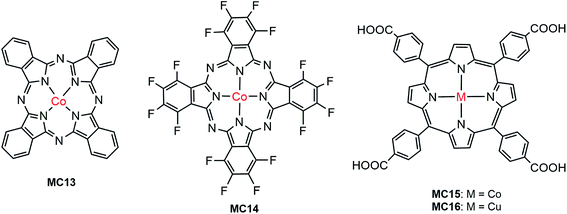
| Fe2O3/MC13 | Hydrophobic interaction | 0.1 M NaOH, pH 13, 100 mW cm−2 | ∼0.5 | 1.0 (0.03) | — | 100 |
| Fe2O3/MC14 | 1.0 | 0.8 (0.2) | Stable over 2 h PEC test at 1.37 V | |||
| BiVO4/MC15 | COOH | 0.1 M Na2SO4, pH 6.8, 100 mW cm−2 | 2.1 | 0.3 (0.4) | Stable over 2 h PEC test at 1.4 V | 94 |
| BiVO4/MC16 | COOH | 0.1 M NaClO4, pH 5.5, 100 mW cm−2, λ > 430 nm | — | ∼0.64 (0.35) | Photocurrent declined during PEC test | 101 |
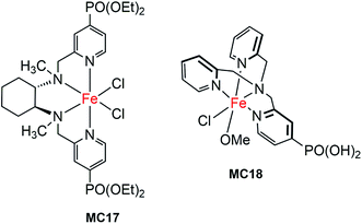
| WO3/MC17 | PO(OEt)2 | 0.1 M Na2SO4, pH 3, 100 mW cm−2 | 1.1 | 0.5 (0) | Slow desorption of MC | 102 |
| WO3/MC18 | PO(OH)2 | 0.1 M Na2SO4, pH 3, 200 mW cm−2 | 1.6 | 0.5 (0) | Slow desorption of MC | 103 |
3.1 Molecular ruthenium catalyst-modified hybrid photoanodes
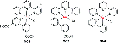
The pioneer work in developing MC-modified hybrid photoanodes was reported by Zhuang and co-workers in 2013.79 To distinguish the contributions of the catalytic effect of the grafted MC and the heterojunction effect of the SC/molecule interface, three Ru catalysts (MC1, MC2, MC3, Fig. 4) were used to modify α-Fe2O3 electrodes. Catalysts MC2 and MC3 bearing a 2-phenylpyridine ligand displayed higher electrocatalytic activity than MC1 containing a 2,2′-bipyridine ligand. MC1 and MC2 were covalently linked to the surface of α-Fe2O3 electrodes through a carboxylate linkage, while MC3 without anchor group was adhered to the α-Fe2O3 surface with Nafion film. The Fe2O3/MC2 photoanode exhibited a photocurrent density of 0.18 mA cm−2 at 1.23 V in pH 3 buffer solution under 66 mW cm−2 illumination, which was approximately 1.5- and 2-fold higher than that observed for the Fe2O3/MC1 and the pristine α-Fe2O3, respectively. Besides, the photovoltages were about 200 mV for Fe2O3/MC1 and 300 mV for Fe2O3/MC2. The discrepancy between the performances of Fe2O3/MC1 and Fe2O3/MC2 was attributed to the different electrocatalytic properties of the two OER catalysts. In another aspect, the Fe2O3/MC3 displayed a lower photocurrent density (0.11 mA cm−2) than the Fe2O3/MC2. These comparative studies revealed that proper design of the ligands of MCs could make the hybrid photoanodes benefit from both the high catalytic activity of grafted catalysts and the heterojunction effect of the SC/molecule interface.In the same year as the publication of Fe2O3/MC1–MC3 photoanodes, the first MC-modified WO3 photoanode was reported by Fujita and co-workers.95 The Ru catalyst MC4 (Fig. 5) had two configurational isomers, distal (d) and proximal (p), due to the asymmetric nature of the ligand pynap (pynap = 2-(pyrid-2′-yl)-1,8-naphthyridine). Of these isomers, only the d-MC4 displayed electrocatalytic activity toward WOR. To suppress the photoinduced isomerization of the active d-MC4 to the inactive p-MC4, the d-MC4 was anchored to the surface of the WO3 photoanode through a phosphonate group. Compared to the pristine WO3 electrode, the WO3/d-MC4 exhibited ∼60 mV cathodic shift at 1 mA cm−2 in the J–E curve measured in 0.5 M KPF6/0.1 M HNO3 under simulated 1-sun illumination. Unfortunately, the plateau photocurrent density decreased from 2.1 mA cm−2 for bare WO3 to 1.8 mA cm−2 for the WO3/d-MC4. The decrease in photocurrent was ascribed to partial visible light absorption by the Ru catalyst and charge recombination within the catalyst layer. An almost complete desorption of d-MC4 from the WO3 surface was observed over the course of 30 min, indicating the easy hydrolysis of surface PO–W bonds under testing conditions.
In 2015, de Respinis, Joya and their co-workers reported the first MC-modified BiVO4 photoanode.96 The Ru catalyst MC5 (Fig. 5) was grafted onto the surface of a planar BiVO4 photoanode through a carboxylate linkage. The photocurrent density of the BiVO4/MC5 was significantly enhanced at low potentials (0.6–1.7 V) as compared to that of the pristine BiVO4 in 0.1 M neutral PBS under 100 mW cm−2 illumination. Specifically, it was 5.5 times higher than that of the bare BiVO4 electrode at 0.8 V. Compared with the performance of the BiVO4 photoanodes modified by CoPi and RuO2, two of the most effective inorganic catalysts for OER, the BiVO4/MC5 displayed a significantly higher photocurrent than BiVO4/RuO2 and BiVO4/CoPi under front illumination. More importantly, the Eonset (at 0.1 mA cm−2) of photocurrent for the BiVO4/MC5 was about 300 mV more negative than that of bare BiVO4, and it was 100 mV more negative than that of BiVO4/CoPi. No desorption and degradation of the catalyst was observed for the BiVO4/MC5 in neutral solution at 1.23 V under 100 mW cm−2 illumination over a period of 1.8 h. It is worth noting that when MC5, CoPi, and RuO2 were coated onto FTO, FTO/RuO2 exhibited a superior electrocatalytic activity with an overpotential of about 0.25 V at 1 mA cm−2, while FTO/CoPi and FTO/MC5 displayed overpotentials of 0.7 and 0.8 V, respectively. These results indicate that the electrocatalytic activity of a catalyst is not the only important factor that one should consider when selecting an appropriate catalyst to construct an effective SC/catalyst composite photoelectrode. Some other factors, such as the light absorbing properties of catalysts, the SC/catalyst interface property, the surface charge recombination probability, as well as the penetrating ability of ions in the catalyst layer, also significantly influence the performance of composite photoelectrodes. Here the BiVO4/MC5 photoanode benefits from the low light absorption of MC5 in the UV-vis-NIR range, the pronounced reduction of surface charge recombination, and the enhanced oxygen evolution kinetics.
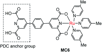
The instability of MC-modified SC photoelectrodes with carboxylate or phosphate linkages to metal oxide surfaces in basic solution remains an intractable problem. To improve the stability of the linkages between MC and SCM, 2,6-pyridinedicarboxylic acid (PDC) was used as an anchor to tether a Ru catalyst (MC6, Fig. 6) onto the surface of α-Fe2O3 nanorod array (NA) film.97 Indeed, the Fe2O3 NA/MC6 displayed excellent photocurrent stability in 1 M KOH solution under visible light illumination with a bias of 1.4 V over 2.78 h. The electrochemical impedance spectroscopic (EIS) studies indicated that the resistance at the Fe2O3/electrolyte interface was significantly reduced after the surface of the α-Fe2O3 film was modified by MC6, and therefore the photocurrent density was increased from 2 mA cm−2 for bare α-Fe2O3 NA photoanode to 3 mA cm−2 for the Fe2O3 NA/MC6. Although immobilization of MC6 on the α-Fe2O3 NA led to an apparent increase of photocurrent, the Eonset (0.8 V) of photocurrent displayed by the Fe2O3 NA/MC6 was just the same as that observed for the pristine α-Fe2O3 NA photoanode.
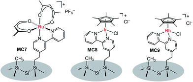
In addition to metal oxide SC photoanodes, the n-type Si electrode was also integrated with MCs. The Ru complex MC7 was grafted onto the mixed methyl/bipyridyl-functionalized Si surface by ligand substitution of Ru(acac)2(coe)2 (acac = acetylacetonate, coe = cis-cyclooctene) with an immobilized bipyridyl moiety (Fig. 7).104 In a similar approach, the Ir (MC8) and Rh (MC9) catalysts were also attached onto the surface of Si electrodes. After assembly of the metal complexes, the Si surface retained its highly favorable photoelectronic properties. Unfortunately, although the immobilized metal complexes retained their molecular natures, all three MC-modified hybrid Si electrodes were very unstable under electrochemical cycling conditions (in CH3CN with a sweep width of 0 V to −1.5 V vs. Fc+/0) due to the rapid detachment of immobilized metal complexes from the Si surface upon electrochemical reduction, possibly caused by ligand-centered reduction. The poor stability of these noble metal-modified Si electrodes thwarted further studies of their photocatalytic activities.
3.2 Molecular iridium catalyst-modified hybrid photoanodes
Molecular iridium catalysts are the most attractive WOCs used for developing VLASC/MC heterojunction WO photoanodes, in terms of their very high activity and relatively low overpotentials.105 Unlike most OER MCs, some iridium MCs feature unique stability in aqueous solutions at low pH. In 2015, Brudvig and co-workers found that a di-μ-oxo IrIV,IV dimer (MC10), formed by activation of a mononuclear IrIII precursor, [Cp*Ir(pyalc)OH] (Cp* = pentamethylcyclopentadinenyl, pyalc = 2-(2′-pyridyl)-2-propanolate), with NaIO4 in water, rapidly self-bound to the surface of metal oxide electrodes (Fig. 8).106 Such direct binding was stable in aqueous solutions over a wide range of pH values (pH 1–12). Here, the N,O-chelating ligand played a key role for the outstanding stability of the framework of this IrIV,IV dimer. For Cp*Ir complexes having only monodentate ligands, the degradation of the complexes was unavoidable, leading to the formation of IrOx particles under water oxidizing conditions.107 The immobilized MC10 displayed higher electrocatalytic activity than the bulk IrOx material for OER in acidic solutions (pH 2.6) and retained its molecular nature over long-term electrolysis. | ||
| Fig. 8 Oxidation of the Cp*Ir monomer to the dimer MC10, followed by direct binding of MC10 onto the α-Fe2O3 surface. | ||
An ultra-thin monolayer of MC10 was covalently grafted to the surface of the α-Fe2O3 photoelectrode. Compared to the PEC performance of the bare hematite electrode, the photocurrent density of Fe2O3/MC10 was enhanced by about 0.5 mA cm−2 (from 0.4 to 0.9 mA cm−2), at a bias of 1.23 V in 0.1 M KNO3 at pH 1 under illumination of simulated sunlight, and the Eonset of photocurrent was cathodically shifted by 0.25 V (from 0.85 to 0.6 V).98 The Fe2O3/MC10 demonstrated a similar PEC performance to that of the Fe2O3/IrOx under identical conditions, but it was less stable than the Fe2O3/IrOx. During the long-time photolysis of water, the rate of O2 evolution from the Fe2O3/MC10 started to decrease after 60 min and leveled off after 80 min under testing conditions. The decrease in O2 evolution efficiency was most likely caused by the catalyst detachment, instead of degradation, due to the corrosion of hematite in highly acidic solution. Replacement of hematite with a more acid-stable, narrow-band metal oxide, such as WO3, may improve the stability of the molecular iridium catalyst-based hybrid photoanodes in highly acidic solutions.
The further in-depth studies, made by Brudvig and Wang, on the kinetics at the Fe2O3-based photoanode/electrolyte interfaces of bare Fe2O3, Fe2O3/MC10, and Fe2O3/IrOx, provided clear experimental evidence for better understanding the mechanism of the effects of molecular (MC10) and material (IrOx) catalysts modified on Fe2O3 photoanodes.108 The kinetic data obtained from intensity-modulated photocurrent spectroscopic (IMPS) and photoelectrochemical impedance spectroscopic (PEIS) studies revealed that the MC10 and IrOx attached on Fe2O3 surfaces played roles in the PEC performance of Fe2O3-based photoanodes in distinct ways. The monolayer of MC10 on the Fe2O3 surface did not change the surface electronic states of the Fe2O3|H2O interface; therefore, it could not stop the charge transfer pathways inherent to the Fe2O3|H2O interface, but it could open up additional lower-barrier charge-transfer pathways via the molecular iridium catalyst (Fig. 9). Thus, the MC10 on the surface of the Fe2O3 photoanode enhanced the PEC performance by speeding up hole transfer from hematite to the catalyst, without reducing the surface recombination rate. In contrast, the dense IrOx film on the Fe2O3 surface completely changed the characteristic surface states of the Fe2O3|H2O interface, thus leading to the replacement of the charge transfer pathways inherent to the Fe2O3|H2O interface with new pathways, so as to suppress both the direct hole transfer through Fe2O3 to H2O and the surface charge recombination. The IrOx film on the Fe2O3 photoanode therefore improved the PEC performance by both speeding up the forward WOR kinetics and by reducing the rate of surface recombination. Furthermore, studies on the H/D kinetic isotope effects (KIE) unveiled that the OER occurring at MC10 and IrOx took place in distinct mechanisms. For Fe2O3/MC10, the rate-determining step (RDS) of WOR was the hole transfer from Fe2O3 to MC10, and WOR occurred rapidly at the molecular iridium catalyst. In contrast, for Fe2O3/IrOx, WOR is the RDS, viz. the hole transfer from IrOx to H2O, rather than the hole transfer from Fe2O3 to IrOx.
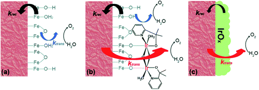 | ||
| Fig. 9 Schematic of the kinetic models for (a) bare α-Fe2O3, (b) α-Fe2O3 with MC10, and (c) α-Fe2O3 with IrOx. Here, krec is the rate constant of charge recombination and ktrans is the rate constant of hole transfer from the surface to the solution. Reproduced from ref. 108 with permission from the Royal Society of Chemistry. | ||
Immediately following this work, studies made by Ozin and co-workers provided a deeper insight into the effect of the molecular iridium catalyst on the different hematite materials. The catalyst MC10 was immobilized onto an ultrathin H2-treated hematite film,99 which featured a non-stoichiometric α-Fe2O3−x structure with oxygen vacancies. The Fe2O3−x/MC10 displayed a larger photocurrent response (0.28 mA cm−2 at 1.75 V) than bare Fe2O3−x electrode, with 200–300 mV cathodic shift in photocurrent onset potential in pH 7.3–7.4 electrolytes under 100 mW cm−2 illumination. It was found that the monolayer of the iridium catalyst on the H2-treated hematite film substantially reduced the charge transfer resistance, compared to that for bare Fe2O3−x, but did not appreciably alter the capacitance of the electrode, and accordingly, did not affect the flat-band potentials of the Fe2O3−x photoanode. Moreover, the effect of the iridium catalyst on thermodynamics and Fermi level pinning was also found to be negligible. The improved PEC performance of the Fe2O3−x electrode after modification with the iridium catalyst was attributed to improved interfacial charge transfer and oxygen evolution kinetics, as well as to reduced recombination rate (Fig. 10). In contrast, the modification of an air-treated Fe2O3 photoanode with the iridium catalyst apparently increased the electrocatalytic activity of the electrode in the dark, but the modified air-treated Fe2O3 electrode displayed very limited photocurrent, due to insufficient band bending and fast charge recombination in the air-treated Fe2O3 material. These results reveal that both SCM engineering and MC immobilization are imperative for improving the PEC performance of hybrid photoelectrodes.
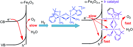 | ||
| Fig. 10 Schematic showing the effect of H2-treatment and iridium catalyst-modification on the performance of the hematite photoanode for WOR. | ||
Very recently, Li and co-workers constructed a highly efficient Ta3N5-based integrated photoanode with its surface decorated with iridium (MC11) and cobalt (MC12) catalysts (Fig. 11).54 This photoanode consisted of a Ta3N5 layer for light harvesting, two hole-storage layers (Ni(OH)x/ferrhydrite (Fh)) for mediating interfacial charge transfer, and a TiOx blocking layer for reducing surface recombination (Ta3N5/TiOx/Fh/Ni(OH)x); the MCs were adhered to the top surface of the integrated photoanode by physisorption. The Ta3N5/TiOx/Fh/Ni(OH)x, without decoration of MC, displayed a photocurrent of 10.7 mA cm−2 at 1.23 V in 1 M NaOH solution, at pH 13.6 under 100 mW cm−2 illumination. The decoration of MC11 or MC12 onto the integrated photoanode brought about an increase of photocurrent to 11.5–11.6 mA cm−2 at 1.23 V. Furthermore, the co-decoration of MC11 and MC12 onto this Ta3N5-based photoanode resulted in a photocurrent of 12.1 mA cm−2 at 1.23 V, with a photocurrent onset potential of about 0.6 V. The applied bias photo-to-current efficiency (ABPE) of this photoanode was 2.5% at 0.9 V. Both the photocurrent and the ABPE of Ta3N5/TiOx/Fh/Ni(OH)x/MC12/MC11 are the state-of-the-art records for VLASC/MC hybrid photoanodes. This work is a perfect example of the construction of highly efficient photoelectrodes by the combination of well-engineered inorganic materials with organometallic MCs. It can be expected that the catalytic activity and stability of this integrated composite photoanode could be further improved by covalently grafting highly active molecular catalysts onto the electrode surface, with a well-designed anchor and an optimized linker.
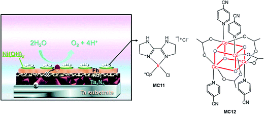 | ||
| Fig. 11 Schematic of the integrated Ta3N5 photoanode modified with molecular iridium and cobalt OER catalysts (MC11, MC12). Reproduced from ref. 54 with permission from the Royal Society of Chemistry. | ||
3.3 Molecular cobalt and copper catalyst-modified hybrid photoanodes
The first noble metal-free VLASC/MC hybrid photoanode was reported by Li, Sun, and their co-workers in 2014.80 In light of the high activity and good stability of Co-oxo cubanes for WOR in homogeneous systems,109,110 the Co-oxo cubane (MC12) that had a strong electron withdrawing group, –CN, at the para position of the pyridine ligand was used for integration with an Fe2O3 photoanode by Nafion film-coating. The Fe2O3/MC12 exhibited a cathodic shift of 400 mV in photocurrent onset potential (ca. 0.67 V) for WOR, as compared to that of the Nafion-coated Fe2O3 and bare Fe2O3 in 0.1 M PBS at pH 8 under illumination (300 W Xe lamp, λ > 420 nm). The transient photocurrent density of Fe2O3/MC12 was 0.4 mA cm−2 at 1.23 V, which was about 8 times that displayed by the Nafion-coated Fe2O3. The cobalt catalyst on the Fe2O3 surface retained its molecular nature and high O2-evolution activity for photoelectrolysis at 1.27 V over a period of 2 h. This finding shows that in terms of photocatalytic activity, photovoltage and stability, the integration of highly active molecular non-noble metal catalysts with visible-light-absorbing SCMs, instead of dye-sensitized SCMs, is a promising approach to creating efficient and low-cost photoelectrodes for PEC water splitting cells.Cobalt phthalocyanine and its derivatives are another type of molecular cobalt catalysts widely studied for WOR in homogeneous systems and on FTO electrodes.111 Takanabe and co-workers immobilized hydrogenated and fluorinated Co–phthalocyanines, MC13 and MC14 (Fig. 12), to the surface of an Fe2O3 photoanode via hydrophobic interaction.100 It was noticed that MC14, bearing a perfluorinated phthalocyanine ligand, displayed higher electrocatalytic activity than MC13, having an unsubstituted phthalocyanine ligand in 0.1 M NaOH solution at pH 13; the current onset potential of MC14 was 110 mV less positive than that of MC13, indicative of the merit of MCs in tuning the redox potential by ligand design and functionalization. Accordingly, the photocurrent density of 1.0 mA cm−2 at 1.23 V for Fe2O3/MC14 was about twice as high as that for Fe2O3/MC13, and about 4 times of that for bare Fe2O3 under 100 mW cm−2 illumination. Notably, the photocurrent density of Fe2O3/MC14 was more than twice as high as that of the fully-inorganic photoanode, Fe2O3/Co–Pi (0.45 mA cm−2 at 1.23 V), partly due to there being no detriment to light absorption by the immobilization of a monolayer of the molecular cobalt catalyst on the surface of Fe2O3. Besides the significant augmentation of photocurrent, the current onset potential was cathodically shifted from 1.03 V for bare Fe2O3, to 0.8 V for Fe2O3/MC14. The evidently improved PEC performance of Fe2O3/MC14 was attributed to enhanced WOR kinetics, accelerated hole transfer from the surface of Fe2O3 to the catalyst, and ameliorated charge separation at the catalyst-SC interface. The long-time photoelectrolysis of water on the Fe2O3/MC14 photoanode demonstrated that this hybrid photoanode, assembled via hydrophobic interaction of the MC to the hematite surface, was quite stable with a sustained photocurrent density of 1.1 mA cm−2 at 1.37 V under simulated 1-sun illumination over a period of 2 h.
As Co–phthalocyanines, Co–porphyrins are also highly active electrocatalysts for WOR.112,113 Very recently, Wu and co-workers immobilized a cobalt porphyrin catalyst (MC15, Fig. 12) onto the surface of a vertically aligned BiVO4 nanosheet (NS) photoanode via covalent linkage through a COOH anchor.94 It was found that the coating of a thin layer of Al2O3 on BiVO4 surface played an important role in the adsorption of the cobalt catalyst and in the passivation of the BiVO4 surface. Immobilization of MC15 to the surface of BiVO4/Al2O3 resulted in a conspicuous increase of photocurrent to 2.1 mA cm−2 at 1.23 V, which was about 2 times as high as that of the bare BiVO4/Al2O3 in 0.1 M Na2SO4 at pH 6.8 under 100 mW cm−2 illumination. Notably, the photocurrent displayed by this earth-abundant metal catalyst-modified BiVO4 photoanode is apparently higher than that of the previously reported molecular ruthenium catalyst-modified BiVO4 electrode (1.4 mA cm−2 at 1.23 V) under similar conditions. Furthermore, the cobalt catalyst on BiVO4/Al2O3 also brought about a significant cathodic shift of approximately 400 mV in photocurrent onset potential, as compared to that of the bare BiVO4/Al2O3. Sufficient experimental evidence revealed that the improved PEC performance of the BiVO4-based photoanode by modification with MC15 was attributed to fast WOR kinetics and efficient injection of photogenerated holes into the electrode/electrolyte interface, which greatly suppressed the charge recombination at the BiVO4 surface. The photocurrent of BiVO4/Al2O3/MC15 declined less than 5% over 2 h of photoelectrolysis at an applied potential of 1.4 V.
A copper catalyst (MC16) containing a porphyrin ligand functionalized with four COOH groups was integrated with BiVO4 to construct a hybrid photoanode for WOR.101 The approach to immobilization of Cu–porphyrin to BiVO4 is different from that to attach the Co–porphyrin catalyst (MC15). The Co–porphyrin complex was prepared prior to the process of self-assembly to BiVO4/Al2O3/MC15, while in the case of Cu–porphyrin, the functionalized porphyrin ligand was first immobilized to the surface of the BiVO4 electrode, followed by a surface coordination reaction of the immobilized porphyrin with Cu2+ ion to afford the BiVO4/MC16 photoanode. It seems that the latter immobilization approach is less effective than the former, due to the incomplete metalation of the grafted porphyrin ligand. A very small photocurrent (<5 μA cm−2 at 1.23 V) was obtained for BiVO4/MC16 in 0.1 M NaClO4 solution at pH 5.5 under the illumination of simulated sunlight (AM 1.5, λ > 430 nm). In addition, the photocurrent gradually declined during extended illumination time, possibly due to the photocatalytic decomposition of the Cu–porphyrin complex.
3.4 Molecular iron catalyst-modified hybrid photoanodes
The first molecular iron catalyst-modified narrow-band SC hybrid photoanode was reported by Bartlett and co-workers in 2014.102 The N4-ligand of an iron WOC was functionalized with two PO(OEt)2 anchors (MC17, Fig. 13),114 and was attached to a WO3 photoanode via phosphonate linkage. The photocurrent density of the iron catalyst-modified WO3 electrode was increased by more than 80%, as compared to that of bare WO3 in 0.1 M Na2SO4 solution at pH 1 under 100 mW cm−2 illumination; specifically, from about 0.7 mA cm−2 at 1.23 V for bare WO3 to 1.3 mA cm−2 for WO3/MC17. The extent of photocurrent enhancement decreased with increase of the solution pH value from pH 1 to pH 7. Although modification of the WO3 surface with MC17 apparently increased the rate of PEC water oxidation at WO3, no appreciable cathodic shift in photocurrent onset was observed under all testing conditions. The photocurrent and the high faradaic efficiency were maintained over a period of 12 h under illumination for WO3/MC17, notwithstanding the unclearness regarding the authentic active catalyst.Following the work mentioned-above, Reisner and co-workers reported another molecular iron catalyst-modified WO3 photoanode.103 The iron complex (MC18, Fig. 13) containing a PO(OH)2-functionalized tris(2-picolyl)amine (TPA(PO(OH)2)) ligand was used to modify a WO3 electrode in consideration of the activity and stability of MC18 for WOR in homogeneous systems at low pH.114 After modification, the transient photocurrent density was increased from about 0.57 mA cm−2 at 1.23 V for bare WO3, to 1.6 mA cm−2 for the iron catalyst-modified WO3 photoanode, but with no shift in the onset potential of photocurrent, in 0.1 M Na2SO4 solution at pH 3 under 200 mW cm−2 illumination. The faradaic efficiency of WO3/MC18 (∼40%) for WOR was doubled as compared to that of bare WO3, although it was still relatively low.
The most important advantage of molecular iron catalyst-modified WO3 photoanodes is that such photoanodes operate in acidic media, which is a preferred condition for the proton reduction reaction. In contrast, the Fe2O3- and BiVO4-based photoanodes generally operate in basic and pH neutral solutions. The first noble-metal-free PEC cell for overall water splitting was installed by using WO3/MC18 as a photoanode and a molecular nickel catalyst-modified TiO2 electrode (TiO2/MC19) as a cathode (Fig. 14).103 Under 100 mW cm−2 illumination at a bias of 1.1 V, this PEC cell produced an approximately 2![[thin space (1/6-em)]](https://www.rsc.org/images/entities/char_2009.gif) :
:![[thin space (1/6-em)]](https://www.rsc.org/images/entities/char_2009.gif) 1 ratio of H2
1 ratio of H2![[thin space (1/6-em)]](https://www.rsc.org/images/entities/char_2009.gif) :
:![[thin space (1/6-em)]](https://www.rsc.org/images/entities/char_2009.gif) O2 in 0.1 M Na2SO4 solution at pH 3, with faradaic efficiencies of about 61% for O2 evolution and 53% for H2 evolution. After photoelectrolysis for a period of 1 h, the nickel WRC on TiO2 retained its molecular entity and activity, while the iron WOC on WO3 slowly desorbed from the surface of the photoanode under testing conditions, but no iron-based deposit was formed on the electrode.
O2 in 0.1 M Na2SO4 solution at pH 3, with faradaic efficiencies of about 61% for O2 evolution and 53% for H2 evolution. After photoelectrolysis for a period of 1 h, the nickel WRC on TiO2 retained its molecular entity and activity, while the iron WOC on WO3 slowly desorbed from the surface of the photoanode under testing conditions, but no iron-based deposit was formed on the electrode.
 | ||
| Fig. 14 Schematic of the PEC water splitting cell with the WO3/MC18 oxygen evolution photoanode wired to the TiO2/MC19 hydrogen evolution cathode. Reproduced from ref. 103 with permission from the Royal Society of Chemistry. | ||
4 VLASC/MC hybrid photocathodes for HER
Although the first report on the VLASC/MC photocathodes can be dated back to 1984,66 the continuous reports have appeared since 2010. In the reported examples of VLASC/MC photocathodes, the SCMs are limited to Si and In/Ga-containing materials, and the immobilized MCs are mostly limited to cobaloximes, DuBois' nickel complexes, and bio-inspired di-iron dithiolate complexes. Until now, only carboxylate and phosphonate were used as anchors to immobilize MCs to the surface of TiO2-protected SC photocathodes. The strategy used for attaching MCs to the unprotected Si and GaP surfaces was the self-initiated photopolymerization of functionalized-vinyl monomers at SC photoelectrodes. By this process, the surface of the electrode was coated with polymer brush containing pendent ligands that direct and assemble MCs to visible-light-absorbing substrates. To date, many reported VLASC/MC hybrid photocathodes have exhibited low photocurrent density and/or small open circuit potential for HER in aqueous electrolytes, or displayed catalytic activity in organic media containing strong organic acids. The benchmark of photocurrent densities reported so far for VLASC/MC photocathodes in aqueous solution is 11 mA cm−2 at zero bias with photocurrent onset potential of 0.75 V for GaInP2/TiO2/MC27/TiO2 under 100 mW cm−2 illumination.115 The performances of reported VLASC/MC hybrid photocathodes have been summarized in Table 2, and the structures of MCs listed in Table 2 can be found in Fig. 15–21.| Photocathode | Anchor or graft method | Testing condition | Photocurrent densitya at 0 V (mA cm−2) | Onset potential (AS)b (V) | Stability | Ref. |
|---|---|---|---|---|---|---|
| a Photocurrent densities given in Table 2 are taken from linear sweep voltammograms at 0 V vs. RHE, unless otherwise noted in the brackets. b AS = anodic shift of photocurrent onset potential as compared to the corresponding bare SC photoanode. c ClMePS = poly(chloromethyl)polystyrene. d PVP = polyvinylpyridine. e PVI = polyvinylimidazole. f diMeOPh = 3,5-dimethoxyphenyl. | ||||||
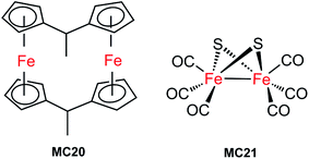
| Si/MC20 | Polymerization with ClMePSc | Neat HBF3OH, 870 mW cm−2 | 194 (−0.54 V vs. SCE) | Stable over 5 days of PEC testing | 66 | |
| InP/MC21 | Direct S coordination | 0.1 M NaBF4, pH 7, 395 nm LED | 0.0003 (−0.2 V vs. NHE) | Stable over 1 h PEC testing at −0.4 V vs. Ag/AgCl | 91 | |
| GaP(100)–PVP/MC22 | PVPd | 1 M PBS, pH 7, 100 mW cm−2 | 2.8 | 0.7 (0.15) | Current declined slowly during CPE testing at 0.17 V | 116 |
| GaP(100)–PVP/MC23 | PVPd | 0.1 M acetate, pH 4.5, solar simulator 100 mW cm−2 | 1.1 | 0.6 (0.03) | Current declined slowly during PEC test at −0.39 V | 117 |
| GaP(100)–PVP/MC23 | PVPd | 0.1 M PBS, pH 7, solar simulator 100 mW cm−2 | 1.3 | 0.61 | Current declined slowly during PEC test at 0 V, TOF 2.1–2.4 s−1 from J–E plot at 0 V | 118 |
| GaP(100)–PVI/MC24 | PVIe | 1.2 | 0.58 | |||
| GaP(111)–PVI/MC24 | PVIe | 0.1 M PBS, pH 7, solar simulator 100 mW cm−2 | 0.89 | 0.64 (0.62) | Stable after initial 5 min decline in current over 1 h PEC test at 0.01 V, TOF 1.9 s−1 from J–E plot at 0 V | 119 |
| GaP(100)/MC25 | Vinylene | 0.1 M PBS, pH 7, solar simulator 100 mW cm−2 | 1.31 | 0.61 (0.04) | <10% loss of activity over 4 h of PEC test at 0 V, TOF ≥ 3.9 s−1 from J–E plot at 0 V | 120 |
| GaP(100)/MC26 | 1.29 | 0.61 (0.04) | Loss of activity gained by MC26 modification over 4 h of PEC test at 0 V | |||
| GaInP2/TiO2/MC27/TiO2 | COOH | 0.1 M NaOH, pH 13, 100 mW cm−2 | 11 | 0.75 (0.15) | After a slow decay in the first 4 h of PEC testing at 0 V, stable over 16 h at 5 mA cm−2, TOF 3.4 s−1 over 20 min | 115 |
| GaInP2/TiO2 + MC28 | Free MC28 | ∼0.2 | ∼0.1 | — | ||
| GaInP2/TiO2/Pt | ALD | 10 | ∼0.85 | Stable during 20 min of PEC testing at 0 V, TOF 2.6 s−1 over 20 min | ||
| Si–Me/MC32 | Si–C bond | 0.2 M LiClO4/MeCN, 15.6 mM TFA, LED 33 mW cm−2 | 6.8 (−0.7 V vs. NHE) | −0.06 V vs. NHE | TOF 285 s−1 from J–E plot with 91 mM TFA at −0.67 V vs. NHE | 121 |
| Si–Me/TiO2/MC33 | PO(OH)2 | 0.2 M LiClO4/MeCN, 30 mM TsOH, LED 33 mW cm−2 | 4.7 (at −0.8 V vs. NHE) | −0.19 V vs. NHE | — | 122 |
| Si–Me/AZO/TiO2/MC33 | PO(OH)2 | 7.77 (−0.75 V vs. NHE) | −0.12 V vs. NHE | — | ||
| Si–diMeOPhf/AZO/TiO2/MC34 | PO(OH)2 | 0.2 M LiClO4/MeCN, 60 mM TsOH, LED 33 mW cm−2 | 7.14 (−0.6 V vs. NHE) | 0.03 V vs. NHE | — | |
| Si/mesoTiO2/MC36 | PO(OH)2 | 0.1 M acetic acid buffer, pH 4.5, 100 mW cm−2, λ > 400 nm | 0.34 | 0.4 (0) | Current declined apparently in the first 10 h of PEC testing at 0 V | 123 |
| Si/mesoTiO2/MC37 | ∼0.33 | 0.4 (0) | Loss of activity gained by MC37 modification after 1 h of PEC testing at 0 V | |||
| Si/MC38 | Drop-casting | 1.0 M HClO4, 28 mW cm−2, λ > 620 nm | 8 | 0.15 (0.55) | 75 | |
| Pillar Si/MC38 | Drop-casting | 9 | 0.15 (0.1) | Current declined slowly over 1 h PEC testing at 0 V | ||
| Pillar Si/MC38 | Drop-casting | 1.0 M HClO4, 86 mW cm−2, λ > 620 nm | 30 | 0.15 (0.1) | ||
| n+p-Si/Ti/TiO2/MC39 | PO(OH)2 | 1.0 M HClO4, AM 1.5, 38.8 mW cm−2, λ > 635 nm | ∼19 | 0.35 | Stable over 1 h PEC testing at 0.2 V | 124 |
4.1 Molecular iron catalyst-modified hybrid photocathodes
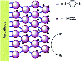
The first molecular iron catalyst-modified VLASC photocathode for proton reduction was reported by Mueller-Westerhoff as early as 1984.66 In this work, the surface of the p-Si photocathode was coated with a co-polymer formed by the reaction of 1-methyl-[1.1]ferrocenophane (MC20, Fig. 15) with poly(chloromethyl)styrene. The modified Si electrode displayed a photocurrent density of 194 mA cm−2 at −0.54 V vs. SCE in neat HBF3OH electrolyte under 870 mW cm−2 illumination. A saturation current density of 231 mA cm−2 was attained by using this electrode, and the high activity maintained over 5 days, indicating the excellent stability of this photocathode under testing conditions. The good performance of this photocathode for proton reduction may be partly attributed to the unusual properties of the neat HBF3OH used as the electrolyte in this test. Hydrogen evolution from neat HBF3OH on the modified Si electrode was observed, but no gas quantification was presented.After a long period of silence in the research on VLASC/MC photoelectrodes, Nann and Pickett, together with their co-workers, reported a Fe2S2 complex-modified p-type InP hybrid photocathode in 2010.91 This photocathode was assembled by first building-up a cross-linked InP nanoarray layer-by-layer onto a gold electrode with 1,4-benzenedithiol as a linker, and then incorporating a di-iron catalyst (MC21, Fig. 16) via direct binding of the sulphide bridges to indium. Under illumination with 395 nm LED at a bias potential of 0.21 V, a photocurrent density of 0.3 μA cm−2 was attained for InP/MC21 in 0.1 M NaBF4 electrolyte at pH 7, which was sustained for at least one hour with a faradaic efficiency of 60% for H2 formation.
4.2 Molecular cobalt catalyst-modified hybrid photocathodes
In recent years, a series of GaP/cobaloxime hybrid photocathodes were reported by Moore and co-workers.116–119,125 These photocathodes were constructed by first covalently attaching the polymer brush with multiple pendent pyridyl (polyvinylpyridine, PVP) or imidazolyl (polyvinylimidazole, PVI) groups onto the surface of a p-GaP substrate by surface initiated photografting and photopolymerization. Such a polymer coat on the GaP surface provided both a protective layer and coordination sites for the assembly of MCs. The cobalt catalysts (MC22–MC24, Fig. 17) were grafted to the GaP surface either via base-promoted chloride replacement of [Co(dmgH2)(dmgH)Cl2] (dmgH = dimethylglyoximate) or via an aqua ligand replacement of Co(dphgBF2)2(H2O)2 (dphgBF2 = (difuoroboryl)diphenylglyoximate) by pyridyl or imidazolyl on the attached polymer brush. The GaP–PVP/MC22 electrode displayed a 2.4 mA cm−2 current density at 0.31 V in 1 M PBS at pH 7 under 100 mW cm−2 illumination, while the GaP–PVP exhibited only about 0.1 mA cm−2 current density at the same potential. In addition, the Eonset of GaP–PVP/MC22 (0.76 V) was positively shifted as compared to that of GaP–PVP (0.69 V). An increase of >200% in the fill factor for the GaP–PVP/MC22, compared to GaP–PVP, implied a dramatic expediting of charge transfer across the SC/electrolyte interface, thanks to the incorporation of the cobaloxime catalyst. The linear dependence of the photocurrent density of GaP–PVP/MC22 on the illumination intensity suggested that the photocarrier transport to the interface was still one of the limiting factors for the performance of cobaloxime-modified GaP photocathodes.116,125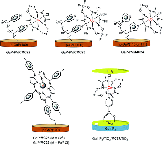 | ||
| Fig. 17 Schematic of GaP–PVP/MC22, GaP–PVP/MC23, GaP–PVI/MC24, GaP/MC25, and GaInP2/TiO2/MC27/TiO2 hybrid photocathodes. | ||
The ligand of the anchored cobalt catalyst can influence the photoactivity of the modified GaP electrode. Replacement of the dmgH in the immobilized cobalt catalyst by a more electron-withdrawing ligand, dphgBF2, improved the stability of cobaloxime complexes towards acid hydrolysis and led to a shift of the reduction potentials of the complexes to less negative, just as the ligand influence observed for the corresponding non-attached cobalt complexes.126 The GaP–PVP/MC22 and GaP–PVP/MC23 displayed almost identical photoactivity at pH 4.5 under simulated AM 1.5 illumination, while the former electrode exhibited a higher photocatalytic activity than the latter at pH 7; more specifically, 1.2 mA cm−2 at 0 V for the former, versus 0.56 mA cm−2 for the latter.117
The functional units at the attached polymer brush used to assemble the cobalt catalyst can also affect the photocatalytic performance of the modified GaP electrode. The GaP–PVI/MC24 was fabricated by using a similar SC–polymer-catalyst approach, by replacing PVP with PVI.118,119 A photocurrent density of 1.2 mA cm−2 at 0 V was obtained with the GaP–PVI/MC24 as the working electrode in 0.1 M PBS at pH 7 under solar simulated illumination at 100 mW cm−2, which was 3 and 4 times that obtained from the GaP–PVI and bare GaP electrode, respectively. Decoration of the GaP surface with the PVI brush led to a positive shift of current onset potential, from 0.02 V to 0.53 V, and the subsequent incorporation of cobalt catalyst into GaP–PVI brought about a further positive shift of Eonset to 0.58 V. Under identical conditions, the GaP–PVP/MC22 displayed a photocurrent density of 1.3 mA cm−2 at 0 V, with Eonset at 0.61 V. In comparison, the potential required by the GaP–PVP/MC22 to achieve a 1 mA cm−2 current density was 170 mV more positive than that required by GaP–PVI/MC24. On the basis of the estimated cobaloxime loadings, the per cobalt centre TOF values were 2.1 and 2.4 s−1 for GaP–PVP/MC22 and GaP–PVI/MC24, respectively. Despite the apparently improved stability of these cobaloxime-modified GaP photocathodes, compared to the bare GaP electrode, a slow decrease in photocurrent was still observed for the GaP–polymer/cobaloxime electrodes during PEC testing, especially in the initial 5 min of illumination, possibly due in part to the loss of surface attached catalyst molecules. The GaP–PVP/cobaloxime(BF2) electrode displayed somewhat better stability than GaP–PVP/cobaloxime in acidic electrolytes.
Two metalloporphyrin-modified GaP hybrid photocathodes, GaP/MC25 and GaP/MC26 (Fig. 17), were reported very recently, in which metalloporphyrins were tethered to the surface of GaP through a pendent vinylphenyl group at the β-position of the porphyrin ligand by a UV-induced grafting approach.120 These photocathodes displayed identical Eonset (0.61 V) and similar photocurrents (1.29–1.31 mA cm−2) at 0 V in 0.1 M PBS at pH 7, under 100 mW cm−2 illumination; however, the applied potential required to reach 1 mA cm−2 by GaP/MC25 was 0.12 V more positive than that required by GaP/MC26. More importantly, the CoII–porphyrin-modified GaP was much more stable than the FeIII–porphyrin-modified GaP under test conditions. The former maintained more than 90% of its H2 evolution activity over 4 h of PEC testing with about 97% faradaic efficiency within the first 30 min of the PEC test, while the latter almost completely lost the photocurrent gained by catalyst modification, due to the degradation of the FeIII–porphyrin complex, with ∼45% faradaic efficiency in the initial 6 min of the PEC test. A high STH conversion efficiency of 11% was attained for GaP/MC25 in a half PEC cell, and the estimated TOF of H2 evolution based on the cobalt porphyrin surface concentration was ≥3.9 s−1, which is the highest TOF reported to date for SC/MC integrated photocathodes operating at 0 V under 1-sun illumination.
Most MC-modified SC photocathodes display photocatalytic activity for HER in organic solvents or neutral and acidic aqueous electrolytes. The p-GaInP2 electrode modified by {(HOOC)py}Co(dmgH)2(Cl) (MC27, (HOOC)py = isonicotinic acid, Fig. 17) is the only one that displays high photocatalytic H2-evolution activity in basic aqueous electrolyte (0.1 M NaOH at pH 13), which is a condition favored by the photoanode counterpart for OER.115 In this photocathode, GaInP2 was covered with a 35 nm TiO2 protective layer, and the cobaloxime catalyst was grafted to the TiO2 surface through the covalent coordination of the carboxylate anchor group. Furthermore, an additional ultrathin TiO2 layer (∼0.4 nm) was decorated onto the surface of GaInP2/TiO/MC27 to protect the carboxylate linkage stability in basic solutions. The GaInP2/TiO2/MC27/TiO2 displayed a photocurrent density of 11 mA cm−2 at 0 V, with Eonset at about 0.75 V under 1-sun illumination. Without the grafted cobaloxime catalyst, the photocurrent of the GaInP2/TiO2 rose slowly at 0 V. Noticeably, the system with GaInP2/TiO2, plus a free cobaloxime catalyst without anchor group, (py)Co(dmgH)2(Cl) (MC28), performed almost identically to the GaInP2/TiO2 electrode alone, indicating the critical role of the covalent linkage between TiO2 and the cobalt catalyst. More importantly, the GaInP2/TiO2/MC27/TiO2 exhibited an outstanding incident photon-to-current efficiency (IPCE) of up to ∼80% across the visible range, which was about 20% higher than the GaInP2/TiO2/Pt electrode. The high IPCE of GaInP2/TiO2/MC27/TiO2 was attributed to the application of a transparent MC layer and a top antireflective TiO2 layer. A TOF of 3.4 s−1 was calculated for GaInP2/TiO2/MC27/TiO2, and 2.6 s−1 for GaInP2/TiO2/Pt over 20 min of PEC testing at 0 V. Even though two layers of TiO2 were adopted, a decrease in photocurrent from 10 to 5 mA cm−2 was observed in the first 4 h of PEC testing with the GaInP2/TiO2/MC27/TiO2 electrode at 0 V, while the current was maintained during a further 16 h of photoelectrolysis experiment, giving a TON of 1.39 × 10⁵. Although the GaInP2/TiO2/MC27/TiO2 displayed remarkable stability compared to the bare GaInP2 electrode, the detachment of MC from the electrode surface and the deactivation of the grafted catalyst at the GaInP2/TiO2/MC27/TiO2 are still problems that need to be solved by developing more stable MCs and more robust anchor modes.
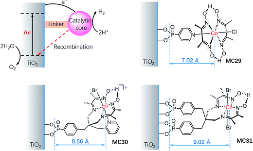
It is important to understand the influences of the molecular structure and the linker on the kinetics of charge separation and recombination in SC/MC hybrid photoelectrodes. Studies on the interfacial electron transfer dynamics of a series of TiO2/cobaloxime photocathodes (Fig. 18) revealed that the electron transfer rate from SC to the attached cobalt catalyst was exponentially dependent on the distance between the TiO2 surface and the cobalt center.127 Systematic transient absorption spectroscopic studies indicated that in the presence of a hole scavenger, triethanolamine (TEOA, 0.1 M), the rate of electron transfer from the TiO2 to the catalyst MC29 was 4 and 10 times faster than to MC30 and MC31, respectively. The results show the importance of the length of the linker and the orientation of the tethered catalyst molecules for controlling the kinetics of charge separation and recombination in SC/MC hybrid photoelectrodes.
4.3 Molecular nickel catalyst-modified hybrid photocathodes
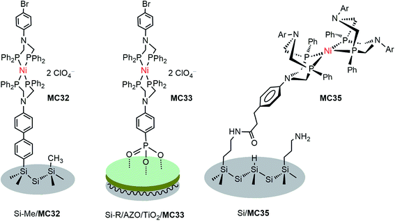
DuBois-type nickel complexes bearing diphosphine ligands with pendant amine base(s) are the most active and robust molecular HER catalysts reported to date.128,129 In very recent years, Rose and co-workers constructed two types of molecular nickel catalyst-modified p-Si photocathodes for HER by covalently tethering a PNP (PNP = Ph2PCH2N(Ar)CH2PPh2) Ni catalyst to a Si substrate with its surface passivated by methylation.121 One example was built by anchoring a Ni(PNP)2 catalyst (MC32) to a Si photocathode via a phenyl ring (Fig. 19). The Si/MC32 was demonstrated to catalyze proton reduction to H2 in LiClO4/CH3CN under the illumination of a broadband LED (33 mW cm−2), with Eonset at −0.06 V vs. NHE and a TOF of 285 s−1, estimated from the current density at −0.67 V in the presence of 91 mM trifluoroacetic acid (TFA). Moreover, this photocathode displayed good stability during consecutive PEC-CV scans in LiClO4/CH3CN electrolyte. Encouragingly, Si/MC32 exhibited higher activity than the Si–Me/Pt cathode at low applied potential (<−0.3 V vs. NHE), and displayed about 0.2 V more positive onset potential than the corresponding free Ni catalyst on a CH3-passivated Si electrode under identical conditions.Several groups have demonstrated that the decoration of a transparent thin layer of metal oxides onto the surface of p-Si can effectively improve the stability of Si electrodes, as well as beneficially modulate the band-edge position of Si electrodes for HER.55,130–132 The other advantage of this strategy is that after decoration of the Si surface with a metal oxide layer, MCs can be tethered to the Si surface through M–O bonds instead of being limited to the Si–C linkage. The representatives of Si/metal oxide/MC hybrid photocathodes are Si–Me/TiO2/MC33 (Fig. 19), Si–Me/AZO/TiO2/MC33 (AZO = aluminum-doped zinc oxide), and Si–diMeOPh/AZO/TiO2/MC33 (diMeOPh = 3,5-dimethoxyphenyl),122 which were constructed by first anchoring a phosphonate-functionalized PNP ligand to the metal oxide layer of a Si electrode, followed by Ni metalation plus capping of the Ni ionic center with another diphosphine ligand (diPhos). The Si–R/AZO/TiO2/MC33 electrode displayed higher Jmax values than the Si–R/AZO/TiO2 without or with free catalyst, [Ni{(Ph2PCH2)2N(C6H4-p-Br)}2] (MC34), in LiClO4/CH3CN electrolyte under illumination. Various factors, such as the Si–R/AZO heterojunction, the Al![[thin space (1/6-em)]](https://www.rsc.org/images/entities/char_2009.gif) :
:![[thin space (1/6-em)]](https://www.rsc.org/images/entities/char_2009.gif) Zn ratio of AZO, the terminal organic group atop the Si surface, the central metal of MC, and the outer capping diphosphine ligand, could influence the performance of Si electrodes for photocatalytic HER. The introduction of a conductive AZO layer between the Si material and the TiO2 layer had beneficial effects on the performance of the hybrid cathodes, viz. facilitating electron transfer to the electrolyte interface, shifting the Eonset of photocurrent to a more positive position, improving the activity and enhancing the saturation current (Jmax), as compared to the corresponding photocathodes with a Si/TiO2 p/n heterojunction interface. In addition, the Al
Zn ratio of AZO, the terminal organic group atop the Si surface, the central metal of MC, and the outer capping diphosphine ligand, could influence the performance of Si electrodes for photocatalytic HER. The introduction of a conductive AZO layer between the Si material and the TiO2 layer had beneficial effects on the performance of the hybrid cathodes, viz. facilitating electron transfer to the electrolyte interface, shifting the Eonset of photocurrent to a more positive position, improving the activity and enhancing the saturation current (Jmax), as compared to the corresponding photocathodes with a Si/TiO2 p/n heterojunction interface. In addition, the Al![[thin space (1/6-em)]](https://www.rsc.org/images/entities/char_2009.gif) :
:![[thin space (1/6-em)]](https://www.rsc.org/images/entities/char_2009.gif) Zn ratio of the AZO layer had apparent influences on the resistance of the AZO film on a Si electrode. The terminal organic groups atop the Si surface, as a soft passivated pad within the Si/AZO or Si/TiO2 p/n heterojunction interface, considerably influenced the morphology of the metal oxide film and the onset potential of the photocurrent. Changing the Ni2+ ion to Co2+ and replacing the capping ligand PNP to DPPE (1,2-bis(diphenylphosphino)ethane) or perfluoro-DPPE all had negative effects on the performance metrics, Eonset and Jmax, of the Si–Me/AZO/TiO2/(PNP)Ni(diPhos) photocathodes. Under optimized conditions, the Si–diMeOPh/AZO/TiO2/MC33 electrode displayed a saturated photocurrent density of 7.14 mA cm−2 with Eonset at 0.03 V vs. NHE in 0.2 M LiClO4/CH3CN containing 60 mM TsOH under the illumination of a broadband LED (33 mW cm−2). The stability of these Si/metal oxides/nickel catalyst hybrid photocathodes in LiClO4/CH3CN electrolyte and their photocatalytic performance in aqueous solutions have not been reported.
Zn ratio of the AZO layer had apparent influences on the resistance of the AZO film on a Si electrode. The terminal organic groups atop the Si surface, as a soft passivated pad within the Si/AZO or Si/TiO2 p/n heterojunction interface, considerably influenced the morphology of the metal oxide film and the onset potential of the photocurrent. Changing the Ni2+ ion to Co2+ and replacing the capping ligand PNP to DPPE (1,2-bis(diphenylphosphino)ethane) or perfluoro-DPPE all had negative effects on the performance metrics, Eonset and Jmax, of the Si–Me/AZO/TiO2/(PNP)Ni(diPhos) photocathodes. Under optimized conditions, the Si–diMeOPh/AZO/TiO2/MC33 electrode displayed a saturated photocurrent density of 7.14 mA cm−2 with Eonset at 0.03 V vs. NHE in 0.2 M LiClO4/CH3CN containing 60 mM TsOH under the illumination of a broadband LED (33 mW cm−2). The stability of these Si/metal oxides/nickel catalyst hybrid photocathodes in LiClO4/CH3CN electrolyte and their photocatalytic performance in aqueous solutions have not been reported.
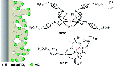
Besides the above-mentioned PNP nickel catalyst-modified photoelectrodes, a masked ester-functionalized DuBois-type P2N2 nickel catalyst (MC35) was attached to the amine-modified surface of p-Si and p-GaP photocathodes.63,133 The evidence from grazing angle attenuated total reflection Fourier transform infrared spectroscopy (GATR-FTIR) and X-ray photoelectron spectroscopy (XPS) suggested that the nickel catalyst was covalently linked to the Si surface through direct Si–C bonds, while it was connected to the GaP surface through bridging oxygen atoms. Unfortunately, the MC35-modified photocathodes lacked photocatalytic activity for HER. The authors assumed that the photocatalytic inactivity of this photocathode was due in large part to the structural distortion of the nickel catalyst following surface attachment. In fact, the long linker between the Si surface and the Ni catalyst could also be a possible reason, if the performance of Si/MC35 is compared to that of the following example of a photocathode, Si/mesoTiO2/MC36, modified with analogous nickel catalyst, but with a shorter linker.
In contrast to Si/MC35, a just published phosphonate-functionalized P2N2 molecular nickel catalyst (MC36)-modified p-Si/mesoporous TiO2 (Si/mesoTiO2) photocathode (Fig. 20) was demonstrated to be active towards HER in aqueous acetic acid solution at pH 4.5 under UV-filtered, simulated solar light illumination (100 mW cm−2, λ > 400 nm).123 Attachment of MC36 (about 38.3 nmol cm−2) to the Si/mesoTiO2 surface through the phosphonate linkage led to an apparent increase in photocurrent density, from 0.1 mA cm−2 at 0 V for Si/mesoTiO2 to 0.34 mA cm−2 for Si/mesoTiO2/MC36, while this hybrid photocathode exhibited almost the same Eonset as Si/mesoTiO2 did, at about 0.4 V. The controlled potential photoelectrolysis (CPP) experiment of Si/mesoTiO2/MC36 at an applied potential of 0 V showed that the faradaic efficiency was decreased from 87% in the early stage of CPP to 76% after 24 h, and in the meantime, the photocurrent and the H2 evolution rate were also apparently decreased in the first 10 h of CPP experiments, due to the initial rapid desorption and/or slow degradation of the catalyst. The TON based on MC36 was about 646 over 24 h of CPP. Post-catalysis characterization by ATR-FTIR and XP spectra suggested that MC36 on the Si/mesoTiO2 surface maintained its molecular integrity during the CPP experiment. In addition, a specially designed phosphonate-functionalized cobaloxime catalyst (MC37)-modified Si/mesoTiO2 photocathode displayed slightly lower photocurrent and smaller Eonset as compared to Si/mesoTiO2/MC36 under identical test conditions. However, the cobaloxime catalyst-modified Si/mesoTiO2 was much less stable than Si/mesoTiO2/MC36, due to the ligand degradation of cobaloxime catalyst. Noticeably, the mesoporous TiO2 layer played important roles in the PEC performance of these Si-based photocathodes as follows: (i) stabilizing the Si surface from passivation, (ii) enabling a high loading of MCs, (iii) affording a fast electron transfer from the light harvester to the bound MCs, and (iv) acting as a hole-blocking layer to reduce the probability of charge recombination between MC and Si. In these photocathodes, the light-generated electrons were first trapped by the CB of TiO2, and then efficiently transferred to the bound MCs to be used for proton reduction.
4.4 Molecular molybdenum catalyst-modified hybrid photocathodes
In 2011, Chorkendorff and co-workers reported the planar and pillared p-Si photocathodes with their surfaces modified by incomplete cubane-like Mo3S4 clusters (MC38, Fig. 21) via physisorption.75 The photocurrent density of 8 mA cm−2 at 0 V was attained for the MC38-modified planar Si photocathode, with a significant anodic shift of the current onset potential, from −0.4 V for bare planar Si to 0.15 V for Si/MC38 in 1.0 M HClO4 solution under illumination of red-light (λ > 620 nm, 28 mW cm−2). The anodic shift of 0.55 V in the photocurrent onset potential is the largest value ever reported that is caused by the modification of SC photocathodes with MCs. The PEC activity was improved by using a Si photocathode of pillar arrays to orthogonalize the light capture and charge carrier collection, but the photocurrent density was still lower than 1 mA cm−2 at 0 V. With immobilization of MC38 onto the Si pillar electrode, the photocurrent density was enhanced to 9 mA cm−2 at 0 V, which slowly declined over 1 h of photoelectrolysis experiment. When the intensity of illumination was increased to 85.8 mW cm−2, the pillar Si/MC38 electrode exhibited a high photocurrent density of 30 mA cm−2 at 0 V.The stability of Mo3S4 cluster-modified Si photocathodes was significantly improved by adopting two measures: (i) coating the Si surface, first with a thin layer of Ti and then with a 100 nm protecting layer of TiO2; (ii) using a phosphonate-functionalized Mo3S4 cluster (MC39, Fig. 21) to immobilize the MC on the outermost TiO2 layer through covalent linkage.124 The n+p-Si/Ti/TiO2/MC39 electrode displayed a photocurrent density of 19 mA cm−2 at 0 V, with Eonset at 0.35 V in 1.0 M HClO4 under illumination of red-light (λ > 635 nm, 38.8 mW cm−2). This protected and modified Si electrode was stable at corrosive potentials, and its catalytic activity showed no decline after 1 h of photoelectrolysis at 0.2 V. However, the photocathode was not stable for photoelectrolysis at more reductive potentials, possibly due to molybdenum catalyst detachment and/or degradation. Re-deposition of the catalyst allowed complete recovery of the catalytic activity, indicative of the intact Si substrate during PEC testing. In light of the high photon-to-hydrogen conversion efficiency of these molybdenum catalyst-modified Si electrodes under red-light illumination, they are promising photocathodes for coupling with the large-bandgap photoanodes that absorb the blue-light of the solar spectrum to construct tandem PEC water splitting cells.
5 Concluding remarks and outlook
Immobilization of MCs onto VLASC electrodes is an innovative and promising approach to an efficient water splitting PEC cell. Quite a few comparative results presented in Chapters 3 and 4 have clearly demonstrated that immobilization of MCs has many advantages over free MCs in solution. Firstly, an expedited charge transfer from SC to MC can be expected in virtue of the confined short distance between MC and the surface of SC in a MC-modified SC photoelectrode, which results in the enhancement of photocurrents and the improvement of solar-to-hydrogen/solar-to-oxygen efficiency of photoelectrodes. Secondly, immobilization of MCs on the surface of SC photoelectrodes brings about, in most cases, a cathodic shift of the photocurrent onset potential (Eonset) to different extents, compared to that attained from the corresponding bare SC photoelectrode. Thirdly, it has been found that immobilization of some MCs on an electrode could make them more stable than their counterparts that remain freely in solution.37 Furthermore, immobilization of MCs to form a monolayer on the surface of SC can minimize the amount of catalyst used, which is particularly meaningful for noble metal catalysts in future practical application.Among the VLASC/MC hybrid photoanodes reported to date, only the well-engineered Ta3N5-based composite photoanode with two types of MCs immobilized on its surface (Ta3N5/TiOx/Fh/Ni(OH)x/MC12/MC11) has exhibited a high photocurrent density (12.1 mA cm−2 at 1.23 V) under simulated 1-sun illumination;54 however, its Eonset value of photocurrent and its stability still need great improvement. Notwithstanding, this example indicates that the immobilization of MCs onto a VLASC photoelectrode with well-engineered protecting layer(s) and hole-storage or electron-storage layer(s) is an effective approach to highly efficient photoanodes and photocathodes. Other VLASC/MC hybrid photoanodes based on metal oxide SCs display photocurrent densities lower than 2.2 mA cm−2 at 1.23 V (Table 1), even in the case of immobilization of a molecular noble metal catalyst on the surface of SCMs. In addition to photocurrent, the onset potential of the photocurrent is another parameter concern for a photoelectrode. Among the available examples of photoanodes listed in Table 1, the MC-modified BiVO4 photoanodes display the lowest onset potential of photocurrent, down to 0.3 V.94 It is found that in most cases, modification of MCs on the surfaces of Fe2O3 and BiVO4 photoanodes brings about a cathodic shift in the Eonset for photocurrent, generally by 0.2 to 0.4 V, compared to the Eonset observed from the corresponding bare SC photoanode, possibly resulting from the heterojunction formed between the MC layer and the SC surface. Several exceptions have been noticed, viz. the Fe2O3 NA/MC6 and all three examples of WO3 photoanodes modified with either molecular Ru or Fe catalysts,95,97,102,103 each of which shows an identical Eonset value to that of the pristine SC photoelectrode; the reason for the unshifted Eonset was not discussed in the original papers. In principle, the Eonset value of the photoelectrode is predominantly determined by the band gap and the photophysical properties of the SC used. In addition, the length of the linker between the catalyst metal center and the SC surface, and the surface coverage of the catalyst on a SC photoelectrode may also influence the Eonset value of MC-modified VLASC photoelectrodes. The linker PDC in Fe2O3 NA/MC6 is relatively long, which is suspected of being the cause of unchanged Eonset after MC modification, while for the MC-modified WO3 photoanodes, the unshifted Eonset might be due to the photophysical properties of WO3 itself. Systematic studies on the influences of anchor groups and the length of linkers between MC and SC on the Eonset value are very important and can provide some guidance for designing the proper linkers and anchors for efficient VLASC/MC photoanodes.
For VLASC/MC integrated photocathodes reported to date, only p-Si and p-In- and/or Ga-containing SCMs were used as light harvesters. The narrow bang gap SCMs that feature suitable conduction band edges for electron transfer to HER MCs are very limited. The development of new SCMs that can be used as proper light harvesters for VLASC/MC photocathodes are eagerly anticipated. In addition, Cu2O and some newly published p-type ternary SCMs deserve to be tested as light harvesters for VLASC/MC photocathodes. In the aspect of MCs, studies on VLASC/MC photocathodes have been concentrated on DuBois' nickel complexes and cobaloximes as well as their derivatives, although a number of molecular catalysts were reported to be active for HER. The reasonable grounds for the choice of the nickel catalysts are their low overpotential, high activity, and good stability for HER in aqueous acidic solutions, and the choice of cobaloxime catalysts could mostly be due to their straightforward preparation method and low overpotentials, despite the poor stability of cobaloximes under the conditions of electro- or photoelectrochemical HER.123 Major challenges for adopting other earth abundant MCs to construct VLASC/MC photocathodes for HER include the arduous preparation required for catalysts containing the desired anchor groups, and the difficulty in finding a proper narrow band gap SCM that matches well with the MC in the conduction band of SC and the orbital level of MC for catalysis of HER. In other aspects, the photocathodes reported to date catalyzed HER mostly in neutral and acidic aqueous solutions, or in organic solvents containing strong acids. Considering that the OER, a bottleneck reaction for total water splitting, prefers strong basic conditions, the development of VLASC/MC photocathodes that efficiently operate in basic solutions is especially important for future integration of VLASC/MC photocathodes with photoanodes to construct effective tandem PEC cells. The GaInP2/TiO2/MC27/TiO2 with two TiO2 layers to protect SC and MC, respectively,115 gives the first very promising example of the construction of integrated photocathodes that are highly efficient and fairly stable for HER in strong basic electrolytes.115 This photocathode displayed a jsc of 11 mA cm−2 and a Voc of 0.75 V with a TOF of 3.4 s−1 at 0 V under simulated 1-sun illumination, which is the best performance among the reported SC/MC photocathodes operating in solutions of all pH values. Such a highly efficient photocathode is promising for integration with a photoanode to construct a PEC cell for total water splitting in strong basic solutions at zero or low bias.
The fundamental work on the development of suitable building blocks, i.e., light harvesters, molecular electrocatalysts for OER or HER, and anchor units, is imperative at the present stage. The improvement of the light absorption and charge separation of very limited n- and p-type classic semiconducting materials and the development of new semiconducting materials that feature desired band-gap and band-edge positions by material engineering are the most challenging and important work. Although some new semiconducting materials have been reported in recent years,134 their performances in integration with MCs for OER or HER are still unexplored. The recently emerging perovskite materials are very exciting for application in solar cells. This material can in principle be considered as VLASC in PEC cells for water splitting if the problem of stability against water can be solved. Currently, the majority of OER and HER MCs were studied either in three-component photocatalytic systems with the use of sacrificial electron acceptors for OER or electron donors for HER, or in three-electrode PEC systems with MCs remaining freely in solutions. Some examples have demonstrated that the performance of a MC attached to the SC surface could be quite different from the behavior found for a free corresponding catalyst in organic solvents or in aqueous solutions.115,133 Importantly, the performance of photoelectrodes is considerably influenced by the length and orientation of linkers. For example, the Si photocathode modified with DuBois' P2N2 nickel catalyst MC35 lacks photocatalytic activity for HER, while the Si photocathode modified by an analogous MC (MC36) does display activity for PEC H2 production under visible-light illumination. The discrepancies in the performance of MC35- and MC36-modified Si electrodes with different lengths of linkers are consistent with the findings by transient absorption spectroscopic studies on the kinetics of electron transfer from SC to the tethered cobaloxime catalyst in a series of photocathodes, TiO2/MC29, TiO2/MC30, and TiO2/MC31.123,127,133 These results suggest that the proper length of linkers is one of the crucial factors that should be considered for designing new VLASC/MC photocathodes. More systematic studies are needed to reveal the inherent relationship of the length and orientation of linkers and the kinetics of interfacial charge transfer between SC and tethered MC.
One of the problems for both MC-modified SC photoanodes and photocathodes is the deactivation of electrodes with extended photoelectrolysis periods, due to the detachment and degradation of grafted MCs. Therefore, it is important to investigate whether the MCs maintain their molecular integrity after immobilization and long-term PEC testing by using all available advanced detection techniques. Many examples have demonstrated that covering the surface of unstable SC photoelectrodes, such as Ta3N5, Si, and In/Ga-containing SCs with broad-band metal oxides, mostly titanium oxides, is an effective method to stabilize the SC materials. With respect to MCs, studies on the immobilization of already known molecular electrocatalysts onto SC electrode surfaces are important for understanding the crucial factors that will influence the performance of the surface-attached MC and the interface electron transfer. On the basis of accumulated knowledge from these in-depth studies, novel OER and HER MCs that are more active and more durable than the reported ones can be expected with rational molecular designs. In addition to the intrinsic stabilities of MCs and SCMs, the anchor group and linker between MC and SC have considerable influence on the activity and stability of hybrid photoelectrodes for OER and HER. Hydroxamate, –CONH(OH), has been demonstrated to form a stable attachment on metal oxides, especially on TiO2,87,88 but it has not been used for grafting OER and HER MCs onto the VLASC photocathodes. Better stability is expected for VLASC/MC photoelectrodes with hydroxamate linkages, compared to those with commonly used carboxylate and phosphonate linkages. Besides, the development of new anchor groups with multi-bonding points and the innovation of graft methods for firmly immobilizing MCs on SC surfaces are also important work for the construction of highly efficient and robust photoelectrodes.
In brief, photocurrent, photovoltage, solar-to-hydrogen (or solar-to-oxygen) efficiency, stability, cost, and impact on environment are the major concerns for the construction of MC-modified PEC cells for overall water splitting. Although some encouraging results have been achieved in recent years in the construction of MC-modified VLASC photoanodes and photocathodes, the efficiency and durability of the reported systems are far from the requirements for a viable commercial PEC device used for solar light-induced spontaneous overall water splitting. There is still a long way to go to realize the great aspiration of chemists: using sunlight as the only energy supply to efficiently produce H2 from water at low cost. With the joint effort of scientists engaged in the research on semiconducting nanomaterials and chemists working on the catalysis and organometallic chemistry, we can expect more innovative approaches to stable and spontaneously effective overall water splitting PEC cells that are integrated with MC-modified SC photoanodes and photocathodes.
Acknowledgements
We are grateful to the Natural Science Foundation of China (Grant No. 21373040, 21673028), the Basic Research Program of China (Grant No. 2014CB239402), the Swedish Energy Agency, and the K & A Wallenberg Foundation for financial support of this work.References
- N. S. Lewis and D. G. Nocera, Proc. Natl. Acad. Sci. U. S. A., 2006, 103, 15729 CrossRef CAS PubMed.
- D. G. Nocera, Acc. Chem. Res., 2012, 45, 767 CrossRef CAS PubMed.
- S. Licht, J. Phys. Chem. B, 2001, 105, 6281 CrossRef CAS.
- M. Grätzel, Nature, 2001, 414, 338 CrossRef PubMed.
- J. Luo, J.-H. Im, M. T. Mayer, M. Schreier, M. K. Nazeeruddin, N.-G. Park, S. D. Tilley, H. J. Fan and M. Grätzel, Science, 2014, 345, 1593 CrossRef CAS PubMed.
- C. R. Cox, J. Z. Lee, D. G. Nocera and T. Buonassisi, Proc. Natl. Acad. Sci. U. S. A., 2014, 111, 14057 CrossRef CAS PubMed.
- M. G. Walter, E. L. Warren, J. R. McKone, S. W. Boettcher, Q. Mi, E. A. Santori and N. S. Lewis, Chem. Rev., 2010, 110, 6446 CrossRef CAS PubMed.
- Y. Tachibana, L. Vayssieres and J. R. Durrant, Nat. Photonics, 2012, 6, 511 CrossRef CAS.
- J. Yang, D. Wang, H. Han and C. Li, Acc. Chem. Res., 2013, 46, 1900 CrossRef CAS PubMed.
- T. Hisatomi, J. Kubota and K. Domen, Chem. Soc. Rev., 2014, 43, 7520 RSC.
- J. R. McKone, N. S. Lewis and H. B. Gray, Chem. Mater., 2014, 26, 407 CrossRef CAS.
- Z. Huang, C. Xiang, H.-J. Lewerenz and N. S. Lewis, Energy Environ. Sci., 2014, 7, 1207 Search PubMed.
- T. J. Jacobsson, V. Fjällström, M. Edoff and T. Edvinsson, Energy Environ. Sci., 2014, 7, 2056 CAS.
- M. R. Shaner, H. A. Atwater, N. S. Lewis and E. W. McFarland, Energy Environ. Sci., 2016, 9, 2354 CAS.
- M. S. Prévot and K. Sivula, J. Phys. Chem. C, 2013, 117, 17879 Search PubMed.
- B. Seger, I. E. Castelli, P. C. K. Vesborg, K. W. Jacobsen, O. Hansen and I. Chorkendorff, Energy Environ. Sci., 2014, 7, 2397 CAS.
- Z. Chen, T. F. Jaramillo, T. G. Deutsch, A. Kleiman-Shwarsctein, A. J. Forman, N. Gaillard, R. Garland, K. Takanabe, C. Heske, M. Sunkara, E. W. McFarland, K. Domen, E. L. Miller, J. A. Turner and H. N. Dinh, J. Mater. Res., 2010, 25, 3 CrossRef CAS.
- S. Hu, C. Xiang, S. Haussener, A. D. Berger and N. S. Lewis, Energy Environ. Sci., 2013, 6, 2984 CAS.
- B. A. Pinaud, J. D. Benck, L. C. Seitz, A. J. Forman, Z. Chen, T. G. Deutsch, B. D. James, K. N. Baum, G. N. Baum, S. Ardo, H. Wang, E. Miller and T. F. Jaramillo, Energy Environ. Sci., 2013, 6, 1983 CAS.
- O. K. Varghese and C. A. Grimes, Sol. Energy Mater. Sol. Cells, 2008, 92, 374 CrossRef CAS.
- H. Dotan, N. Mathews, T. Hisatomi, M. Grätzel and A. Rothschild, J. Phys. Chem. Lett., 2014, 5, 3330 CrossRef CAS PubMed.
- A. C. Nielander, M. R. Shaner, K. M. Papadantonakis, S. A. Francis and N. S. Lewis, Energy Environ. Sci., 2015, 8, 16 CAS.
- A. Fujishima and K. Honda, Nature, 1972, 238, 37 CrossRef CAS PubMed.
- J. W. Ager, M. R. Shaner, K. A. Walczak, I. D. Sharp and S. Ardo, Energy Environ. Sci., 2015, 8, 2811 CAS.
- J. Brillet, J.-H. Yum, M. Cornuz, T. Hisatomi, R. Solarska, J. Augustynski, M. Graetzel and K. Sivula, Nat. Photonics, 2012, 6, 824 CrossRef CAS.
- L. M. Peter and K. G. U. Wijayantha, ChemPhysChem, 2014, 15, 1983 CrossRef CAS PubMed.
- C. Ding, J. Shi, Z. Wang and C. Li, ACS Catal., 2017, 7, 675 CrossRef CAS.
- W. J. Youngblood, S.-H. A. Lee, K. Maeda and T. E. Mallouk, Acc. Chem. Res., 2009, 42, 1966 CrossRef CAS PubMed.
- J. Sun, D. K. Zhong and D. R. Gamelin, Energy Environ. Sci., 2010, 3, 1252 CAS.
- K. S. Joya, Y. F. Joya, K. Ocakoglu and R. van de Krol, Angew. Chem., Int. Ed., 2013, 52, 10426 CrossRef CAS PubMed.
- R. Liu, Z. Zheng, J. Spurgeon and X. Yang, Energy Environ. Sci., 2014, 7, 2504 CAS.
- L. Alibabaei, H. Luo, R. L. House, P. G. Hoertz, R. Lopez and T. J. Meyer, J. Mater. Chem. A, 2013, 1, 4133 CAS.
- Z. Han and R. Eisenberg, Acc. Chem. Res., 2014, 47, 2537 CrossRef CAS PubMed.
- D. L. Ashford, M. K. Gish, A. K. Vannucci, M. K. Brennaman, J. L. Templeton, J. M. Papanikolas and T. J. Meyer, Chem. Rev., 2015, 115, 13006 CrossRef CAS PubMed.
- M. Wang, K. Han, S. Zhang and L. Sun, Coord. Chem. Rev., 2015, 287, 1 CrossRef CAS.
- Z. Yu, F. Li and L. Sun, Energy Environ. Sci., 2015, 8, 760 CAS.
- N. Queyriaux, N. Kaeffer, A. Morozan, M. Chavarot-Kerlidou and V. Artero, J. Photochem. Photobiol., C, 2015, 25, 90 CrossRef CAS.
- M. Yamamoto and K. Tanaka, ChemPlusChem, 2016, 81, 1028 CrossRef CAS.
- N. Jiang, M. Sheng and Y. Sun, RSC Green Chem., 2016, 42, 108 CAS.
- X. Zhang, T. Peng and S. Song, J. Mater. Chem. A, 2016, 4, 2365 CAS.
- R. Liu, Y. Lin, L.-Y. Chou, S. W. Sheehan, W. He, F. Zhang, H. J. M. Hou and D. Wang, Angew. Chem., Int. Ed., 2011, 50, 499 CrossRef CAS PubMed.
- Y.-H. Lai, T. C. King, D. S. Wright and E. Reisner, Chem.–Eur. J., 2013, 19, 12943 CrossRef CAS PubMed.
- F. E. Osterloh, Chem. Soc. Rev., 2013, 42, 2294 RSC.
- J. Li and N. Wu, Catal. Sci. Technol., 2015, 5, 1360 CAS.
- X. Yang, R. Liu, Y. He, J. Thorne, Z. Zheng and D. Wang, Nano Res., 2015, 8, 56 CrossRef CAS.
- N. Guijarro, M. S. Prévot and K. Sivula, Phys. Chem. Chem. Phys., 2015, 17, 15655 RSC.
- M. J. Katz, S. C. Riha, N. C. Jeong, A. B. F. Martinson, O. K. Farha and J. T. Hupp, Coord. Chem. Rev., 2012, 256, 2521 CrossRef CAS.
- L. M. Peter, J. Solid State Electrochem., 2013, 17, 315 CrossRef CAS.
- B. Iandolo, B. Wickman, I. Zorić and A. Hellman, J. Mater. Chem. A, 2015, 3, 16896 CAS.
- K. Sivula, J. Phys. Chem. Lett., 2013, 4, 1624 CrossRef CAS PubMed.
- D. Kang, T. W. Kim, S. R. Kubota, A. C. Cardiel, H. Gil Cha and K.-S. Choi, Chem. Rev., 2015, 115, 12839 CrossRef CAS PubMed.
- D. Jing, L. Guo, L. Zhao, X. Zhang, H. Liu, M. Li, S. Shen, G. Liu, X. Hu, X. Zhang, K. Zhang, L. Ma and P. Guo, Int. J. Hydrogen Energy, 2010, 35, 7087 CrossRef CAS.
- S. Chen and L.-W. Wang, Chem. Mater., 2012, 24, 3659 CrossRef CAS.
- G. Liu, S. Ye, P. Yan, F. Xiong, P. Fu, Z. Wang, Z. Chen, J. Shi and C. Li, Energy Environ. Sci., 2016, 9, 1327 CAS.
- D. Bae, B. Seger, P. C. K. Vesborg, O. Hansen and I. Chorkendorff, Chem. Soc. Rev., 2017, 46, 1933 RSC.
- K. Sun, S. Shen, Y. Liang, P. E. Burrows, S. S. Mao and D. Wang, Chem. Rev., 2014, 114, 8662 CrossRef CAS PubMed.
- B. Seger, A. B. Laursen, P. C. K. Vesborg, T. Pedersen, O. Hansen, S. Dahl and I. Chorkendorff, Angew. Chem., Int. Ed., 2012, 51, 9128 CrossRef CAS PubMed.
- B. Seger, T. Pedersen, A. B. Laursen, P. C. K. Vesborg, O. Hansen and I. Chorkendorff, J. Am. Chem. Soc., 2013, 135, 1057 CrossRef CAS PubMed.
- Y. Lin, C. Battaglia, M. Boccard, M. Hettick, Z. Yu, C. Ballif, J. W. Ager and A. Javey, Nano Lett., 2013, 13, 5615 CrossRef CAS PubMed.
- C. G. Morales-Guio, K. Thorwarth, B. Niesen, L. Liardet, J. Patscheider, C. Ballif and X. Hu, J. Am. Chem. Soc., 2015, 137, 7035 CrossRef CAS PubMed.
- M. Hettick, M. Zheng, Y. Lin, C. M. Sutter-Fella, J. W. Ager and A. Javey, J. Phys. Chem. Lett., 2015, 6, 2177 CrossRef CAS PubMed.
- M. H. Lee, K. Takei, J. Zhang, R. Kapadia, M. Zheng, Y.-Z. Chen, J. Nah, T. S. Matthews, Y.-L. Chueh, J. W. Ager and A. Javey, Angew. Chem., Int. Ed., 2012, 51, 10760 CrossRef CAS PubMed.
- D. Cedeno, A. Krawicz and G. F. Moore, Interface Focus, 2015, 5, 20140085 CrossRef PubMed.
- A. Bansal and J. A. Turner, J. Phys. Chem. B, 2000, 104, 6591 CrossRef CAS.
- B. A. MacLeod, K. X. Steirer, J. L. Young, U. Koldemir, A. Sellinger, J. A. Turner, T. G. Deutsch and D. C. Olson, ACS Appl. Mater. Interfaces, 2015, 7, 11346 CAS.
- U. T. Mueller-Westerhoff and A. Nazzal, J. Am. Chem. Soc., 1984, 106, 5381 CrossRef CAS.
- A. Singh and L. Spiccia, Coord. Chem. Rev., 2013, 257, 2607 CrossRef CAS.
- M. D. Kärkäs, O. Verho, E. V. Johnston and B. Åkermark, Chem. Rev., 2014, 114, 11863 CrossRef PubMed.
- S. Berardi, S. Drouet, L. Francàs, C. Gimbert-Suriñach, M. Guttentag, C. Richmond, T. Stoll and A. Llobet, Chem. Soc. Rev., 2014, 43, 7501 RSC.
- J. D. Blakemore, R. H. Crabtree and G. W. Brudvig, Chem. Rev., 2015, 115, 12974 CrossRef CAS PubMed.
- M. R. Nellist, F. A. L. Laskowski, F. Lin, T. J. Mills and S. W. Boettcher, Acc. Chem. Res., 2016, 49, 733 CrossRef CAS PubMed.
- V. Artero and M. Fontecave, Chem. Soc. Rev., 2013, 42, 2338 RSC.
- B. Limburg, E. Bouwman and S. Bonnet, Coord. Chem. Rev., 2012, 256, 1451 CrossRef CAS.
- C. A. Downes and S. C. Marinescu, J. Am. Chem. Soc., 2015, 137, 13740 CrossRef CAS PubMed.
- Y. Hou, B. L. Abrams, P. C. K. Vesborg, M. E. Björketun, K. Herbst, L. Bech, A. M. Setti, C. D. Damsgaard, T. Pedersen, O. Hansen, J. Rossmeisl, S. Dah, J. K. Nørskov and I. Chorkendorff, Nat. Mater., 2011, 10, 434 CrossRef CAS PubMed.
- R. Brimblecombe, G. F. Swiegers, G. C. Dismukes and L. Spiccia, Angew. Chem., 2008, 120, 7445 CrossRef.
- R. Brimblecombe, G. C. Dismukes, G. F. Swiegers and L. Spiccia, Dalton Trans., 2009, 9374 RSC.
- L. Li, L. Duan, Y. Xu, M. Gorlov, A. Hagfeldt and L. Sun, Chem. Commun., 2010, 46, 7307 RSC.
- X. Chen, X. Ren, Z. Liu, L. Zhuang and J. Lu, Electrochem. Commun., 2013, 27, 148 CrossRef CAS.
- B. Zhang, F. Li, F. Yu, X. Wang, X. Zhou, H. Li, Y. Jiang and L. Sun, ACS Catal., 2014, 4, 804 CrossRef CAS.
- A. D. Weisz, A. E. Regazzoni and M. A. Blesa, Solid State Ionics, 2001, 143, 125 CrossRef CAS.
- C. Queffélec, M. Petit, P. Janvier, D. A. Knight and B. Bujoli, Chem. Rev., 2012, 112, 3777 CrossRef PubMed.
- P. J. Hotchkiss, S. C. Jones, S. A. Paniagua, A. Sharma, B. Kippelen, N. R. Armstrong and S. R. Marder, Acc. Chem. Res., 2012, 45, 337 CrossRef CAS PubMed.
- K. Hanson, M. K. Brennaman, H. Luo, C. R. K. Glasson, J. J. Concepcion, W. Song and T. J. Meyer, ACS Appl. Mater. Interfaces, 2012, 4, 1462 CAS.
- Y. Gao, X. Ding, J. Liu, L. Wang, Z. Lu, L. Li and L. Sun, J. Am. Chem. Soc., 2013, 135, 4219 CrossRef CAS PubMed.
- Z. Xu and M. Cotlet, Angew. Chem., Int. Ed., 2011, 50, 6079 CrossRef CAS PubMed.
- B. J. Brennan, J. Chen, B. Rudshteyn, S. Chaudhuri, B. Q. Mercado, V. S. Batista, R. H. Crabtree and G. W. Brudvig, Chem. Commun., 2016, 52, 2972 RSC.
- W. R. McNamara, R. C. Snoeberger III, G. Li, C. Richter, L. J. Allen, R. L. Milot, C. A. Schmuttenmaer, R. H. Crabtree, G. W. Brudvig and V. S. Batista, Energy Environ. Sci., 2009, 2, 1173 CAS.
- K. Takijiri, K. Morita, T. Nakazono, K. Sakai and H. Ozawa, Chem. Commun., 2017, 53, 3042 RSC.
- J. M. Buriak, Chem. Rev., 2002, 102, 1271 CrossRef CAS PubMed.
- T. Nann, S. K. Ibrahim, P.-M. Woi, S. Xu, J. Ziegler and C. J. Pickett, Angew. Chem., Int. Ed., 2010, 49, 1574 CrossRef CAS PubMed.
- K. Fan, F. Li, L. Wang, Q. Daniel, E. Gabrielsson and L. Sun, Phys. Chem. Chem. Phys., 2014, 16, 25234 RSC.
- F. Li, K. Fan, B. Xu, E. Gabrielsson, Q. Daniel, L. Li and L. Sun, J. Am. Chem. Soc., 2015, 137, 9153 CrossRef CAS PubMed.
- B. Liu, J. Li, H.-L. Wu, W.-Q. Liu, X. Jiang, Z.-J. Li, B. Chen, C.-H. Tung and L.-Z. Wu, ACS Appl. Mater. Interfaces, 2016, 8, 18577 CAS.
- D. K. Zhong, S. Zhao, D. E. Polyansky and E. Fujita, J. Catal., 2013, 307, 140 CrossRef CAS.
- M. de Respinis, K. S. Joya, H. J. M. de Groot, F. D'Souza, W. Smith, R. van de Krol and B. Dam, J. Phys. Chem. C, 2015, 119, 7275 CAS.
- K. Fan, F. Li, L. Wang, Q. Daniel, H. Chen, E. Gabrielsson, J. Sun and L. Sun, ChemSusChem, 2015, 8, 3242 CrossRef CAS PubMed.
- W. Li, S. W. Sheehan, D. He, Y. He, X. Yao, R. L. Grimm, G. W. Brudvig and D. Wang, Angew. Chem., Int. Ed., 2015, 54, 11428 CrossRef CAS PubMed.
- J. W. Moir, E. V. Sackville, U. Hintermair and G. A. Ozin, J. Phys. Chem. C, 2016, 120, 12999 CAS.
- K. S. Joya, N. Morlanés, E. Maloney, V. Rodionov and K. Takanabe, Chem. Commun., 2015, 51, 13481 RSC.
- S. Nakashima, R. Negishi and H. Tada, Chem. Commun., 2016, 52, 3665 RSC.
- B. M. Klepser and B. M. Bartlett, J. Am. Chem. Soc., 2014, 136, 1694 CrossRef CAS PubMed.
- T. E. Rosser, M. A. Gross, Y.-H. Lai and E. Reisner, Chem. Sci., 2016, 7, 4024 RSC.
- J. R. C. Lattimer, J. D. Blakemore, W. Sattler, S. Gul, R. Chatterjee, V. K. Yachandra, J. Yano, B. S. Brunschwig, N. S. Lewis and H. B. Gray, Dalton Trans., 2014, 43, 15004 RSC.
- J. M. Thomsen, D. L. Huang, R. H. Crabtree and G. W. Brudvig, Dalton Trans., 2015, 44, 12452 RSC.
- S. W. Sheehan, J. M. Thomsen, U. Hintermair, R. H. Crabtree, G. W. Brudvig and C. A. Schmuttenmaer, Nat. Commun., 2015, 6, 6469 CrossRef CAS PubMed.
- L. Badia-Bou, E. Mas-Marza, P. Rodenas, E. M. Barea, F. Fabregat-Santiago, S. Gimenez, E. Peris and J. Bisquert, J. Phys. Chem. C, 2013, 117, 3826 CAS.
- W. Li, D. He, S. W. Sheehan, Y. He, J. E. Thorne, X. Yao, G. W. Brudvig and D. Wang, Energy Environ. Sci., 2016, 9, 1794 CAS.
- N. S. McCool, D. M. Robinson, J. E. Sheats and G. C. Dismukes, J. Am. Chem. Soc., 2011, 133, 11446 CrossRef CAS PubMed.
- G. L. Ganga, F. Puntoriero, S. Campagna, I. Bazzan, S. Berardi, M. Bonchio, A. Sartorel, M. Natali and F. Scandola, Faraday Discuss., 2012, 155, 177 RSC.
- N. Morlanés, K. S. Joya, K. Takanabe and V. Rodionov, Eur. J. Inorg. Chem., 2015, 49 CrossRef.
- D. Wang and J. T. Groves, Proc. Natl. Acad. Sci. U. S. A., 2013, 110, 15579 CrossRef CAS PubMed.
- A. Han, H. Jia, H. Ma, S. Ye, H. Wu, H. Lei, Y. Han, R. Cao and P. Du, Phys. Chem. Chem. Phys., 2014, 16, 11224 RSC.
- J. L. Fillol, Z. Codolà, I. Garcia-Bosch, L. Gàmez, J. J. Pla and M. Costas, Nat. Chem., 2011, 3, 807 CrossRef CAS PubMed.
- J. Gu, Y. Yan, J. L. Young, K. X. Steirer, N. R. Neale and J. A. Turner, Nat. Mater., 2016, 15, 456 CrossRef CAS PubMed.
- A. Krawicz, J. Yang, E. Anzenberg, J. Yano, I. D. Sharp and G. F. Moore, J. Am. Chem. Soc., 2013, 135, 11861 CrossRef CAS PubMed.
- D. Cedeno, A. Krawicz, P. Doak, M. Yu, J. B. Neaton and G. F. Moore, J. Phys. Chem. Lett., 2014, 5, 3222 CrossRef CAS PubMed.
- A. M. Beiler, D. Khusnutdinova, S. I. Jacob and G. F. Moore, Ind. Eng. Chem. Res., 2016, 55, 5306 CrossRef CAS.
- A. M. Beiler, D. Khusnutdinova, S. I. Jacob and G. F. Moore, ACS Appl. Mater. Interfaces, 2016, 8, 10038 CAS.
- D. Khusnutdinova, A. M. Beiler, B. L. Wadsworth, S. I. Jacob and G. F. Moore, Chem. Sci., 2017, 8, 253 RSC.
- J. Seo, R. T. Pekarek and M. J. Rose, Chem. Commun., 2015, 51, 13264 RSC.
- H. J. Kim, J. Seo and M. J. Rose, ACS Appl. Mater. Interfaces, 2016, 8, 1061 CAS.
- J. J. Leung, J. Warnan, D. H. Nam, J. Z. Zhang, J. Willkomm and E. Reisner, Chem. Sci., 2017 10.1039/c7sc01277b.
- B. Seger, K. Herbst, T. Pedersen, B. Abrams, P. C. K. Vesborg, O. Hansen and I. Chorkendorff, J. Electrochem. Soc., 2014, 161, H722 CrossRef.
- A. Krawicz, D. Cedeno and G. F. Moore, Phys. Chem. Chem. Phys., 2014, 16, 15818 RSC.
- P. Connolly and J. H. Espenson, Inorg. Chem., 1986, 25, 2684 CrossRef CAS.
- A. Reynal, J. Willkomm, N. M. Muresan, F. Lakadamyali, M. Planells, E. Reisner and J. R. Durrant, Chem. Commun., 2014, 50, 12768 RSC.
- A. L. Goff, V. Artero, B. Jousselme, P. D. Tran, N. Guillet, R. Métayé, A. Fihri, S. Palacin and M. Fontecave, Science, 2009, 326, 1384 CrossRef PubMed.
- M. L. Helm, M. P. Stewart, R. M. Bullock, M. R. DuBois and D. L. DuBois, Science, 2011, 333, 863 CrossRef CAS PubMed.
- B. Seger, T. Pedersen, A. B. Laursen, P. C. K. Vesborg, O. Hansen and I. Chorkendorff, J. Am. Chem. Soc., 2013, 135, 1057 CrossRef CAS PubMed.
- Y. Lin, C. Battaglia, M. Boccard, M. Hettick, Z. Yu, C. Ballif, J. W. Ager and A. Javey, Nano Lett., 2013, 13, 5615 CrossRef CAS PubMed.
- C. G. Morales-Guio, K. Thorwarth, B. Niesen, L. Liardet, J. Patscheider, C. Ballif and X. Hu, J. Am. Chem. Soc., 2015, 137, 7035 CrossRef CAS PubMed.
- G. F. Moore and I. D. Sharp, J. Phys. Chem. Lett., 2013, 4, 568 CrossRef CAS PubMed.
- K. Sivula and R. van de Krol, Nat. Rev. Mater., 2016, 1, 15010 CrossRef CAS.
| This journal is © The Royal Society of Chemistry 2017 |


