Hydrophilic–hydrophobic diblock copolymers based on polyphenylenes for cathode ionomers of fuel cells†
K.
Akizuki
ab,
A.
Ohma
b,
S.
Miura
a,
T.
Matsuura
a,
M.
Yoshizawa-Fujita
 a,
Y.
Takeoka
 a and
M.
Rikukawa
 *a
*a
aDepartment of Materials and Life Sciences, Sophia University, 7-1 Kioi-cho, Chiyoda-ku, Tokyo 1028554, Japan. E-mail: m-rikuka@sophia.ac.jp
bNissan Motor Company, Limited, Nissan Research Center, Yokohama, Kanagawa 2378523, Japan
First published on 25th May 2017
Abstract
Polyphenylene-based hydrophilic–hydrophobic diblock copolymers were developed and used as ionomers in the catalyst layers (CLs) of polymer electrolyte membrane fuel cells. The introduction of aliphatic side chains into the polymer backbone provided high oxygen transport properties in the CLs and high overall performance of the fuel cells.
Polymer electrolyte membrane fuel cells (PEMFCs) are one of the most promising clean energy conversion technologies for the reduction of carbon dioxide emissions associated with energy generation. PEMFCs utilize polymer electrolytes as polymer electrolyte membranes (PEMs) and ionomers in the CLs. PEMs act as proton conductors and gas barriers between the electrodes, while the ionomers used in the CLs are required to have high proton conductivity and gas permeability. Research towards superior PEMs has focused on improvements and understanding of the mechanism of proton conductivity, gas barrier properties, and durability in addition to developments of measurement techniques of membrane properties.1–4 Achieving improvements in mass transport requires systems in which the acidity and phase separation of the membrane are controlled.5–11
In studies of ionomers in CLs, most researchers have employed the same polymer electrolytes that were developed for PEMs.12–19 Therefore, no molecular design strategies to develop novel CL ionomers have been presented to date, and there are few reports of hydrocarbon-based ionomers that have a comparable gas permeability to Nafion® ionomers.
Recently, our group has reported hydrophilic–hydrophobic polyphenylene-based diblock copolymers with aliphatic side chains (SBuH, Fig. 1).20,21 These SBuH ionomers had well-controlled molecular weights (Mw) and polydispersity indices (PDIs) and showed both clear phase separation and good proton conduction. In addition, the flexible side chains present in SBuH introduce a self-plasticizing effect, which is expected to increase the gas permeability. In this study, we investigated the water uptake and gas permeability of the SBuH ionomer in order to understand the relationship between the chemical structure of ionomers and the electrochemical properties of the CLs by using the diblock copolymers as model electrolytes. We also demonstrated the excellent I–V performance of PEMFCs that used SBuH as the cathode ionomer.
For this study, SBuH was synthesized by catalyst transfer polycondensation, as per our previous reports.20,21 The Mw and PDI of SBuH were 121![[thin space (1/6-em)]](https://www.rsc.org/images/entities/char_2009.gif) 000 g mol−1 and 1.3, respectively, as determined by GPC (THF eluent). The m
000 g mol−1 and 1.3, respectively, as determined by GPC (THF eluent). The m![[thin space (1/6-em)]](https://www.rsc.org/images/entities/char_2009.gif) :
:![[thin space (1/6-em)]](https://www.rsc.org/images/entities/char_2009.gif) n ratio was 1
n ratio was 1![[thin space (1/6-em)]](https://www.rsc.org/images/entities/char_2009.gif) :
:![[thin space (1/6-em)]](https://www.rsc.org/images/entities/char_2009.gif) 1.08, as obtained by 1H NMR, and the ion exchange capacity (IEC) of SBuH was 2.49 meq g−1, as determined by back titration.
1.08, as obtained by 1H NMR, and the ion exchange capacity (IEC) of SBuH was 2.49 meq g−1, as determined by back titration.
The water uptake (WU), the swelling volume ratio (V), and the contact angle of the SBuH and Nafion® membranes were measured, as these properties are indicative of their suitability as ionomers in the CLs. Fig. 2 shows the WU values and the number of water molecules per sulfonic acid group (λ) of the SBuH and Nafion® membranes as a function of relative humidity (RH) at 80 °C. The WU and λ of both membranes increased with increasing RH. The λ values of SBuH membranes were close to those of Nafion® membranes at higher RH and reached the same value (9.5) at 90% RH. These results suggest that the amount of adsorbed water in the SBuH CLs is comparable to that of the Nafion® CLs when the same number of sulfonic acid groups and the same catalyst type were present in both the SBuH and the Nafion® CLs. When immersed in water at 80 °C, the V values of the SBuH and Nafion® membranes were 172% and 72%, respectively. The averaged values of the contact angle of SBuH and Nafion® membranes were 91 ± 8° and 97 ± 2°, respectively, at 25 °C and 50% RH. Considering these results, an excess of SBuH is predicted to cause an increase in the oxygen transport resistance of SBuH CLs because of their increased swollen volume in the pore, compared to Nafion® CLs. The values of the proton conductivity of SBuH membranes were 0.48 mS cm−1 and 192 mS cm−1 at 30% RH and 90% RH, respectively (Fig. S1†). These values were consistent with those of a previous study of SBuH membranes. It was considered that SBuH membranes studied in this report had similar phase separation as reported previously.20
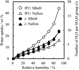 | ||
| Fig. 2 Water uptake and number of water molecules per sulfonic acid group of SBuH and Nafion® membranes at 80 °C as a function of relative humidity. | ||
The hydrogen and oxygen permeability coefficients (PH2 and PO2) of the SBuH and Nafion® membranes are shown in Fig. 3 as a function of RH at 80 °C. The PH2 and PO2 values of SBuH membranes were smaller than those of Nafion® membranes at low RH, while SBuH membranes showed a larger increase in the PH2 and PO2 than Nafion® membranes with increasing RH. SBuH membranes showed comparable PH2 and PO2 values to Nafion® membranes above 80% RH, in contrast to most of the previously reported sulfonated polyaromatic membranes, which showed lower gas permeability coefficients than Nafion® membranes over wide RH ranges.22–26
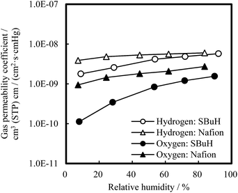 | ||
| Fig. 3 Gas (H2, O2) permeability coefficients of SBuH and Nafion® membranes at 80 °C as a function of relative humidity. | ||
Dynamic mechanical analysis (DMA) was performed under controlled temperature and RH conditions to understand the higher gas permeability of SBuH. A thermal transition temperature was observed at ∼120 °C for both membranes (Fig. S2(a)†) under dry conditions, in contrast to previously reported sulfonated polyaromatic membranes that lacked aliphatic side chains.22 At 80 °C and 90% RH, the E′ values of SBuH and Nafion® membranes were 45 MPa and 102 MPa, respectively, and the E′′ value of both membranes was ∼14 MPa. However, under dry conditions, the SBuH membranes showed larger values of both E′ and E′′ than the Nafion® membranes (Fig. S2(b)†). The results of differential scanning calorimetry (Fig. S3†) showed that the SBuH membranes had an endothermic peak around 95 °C, indicating that the molecular motion of side chains increased and/or the interaction among the polymer chains weakened with increasing temperature, and also these effects might be induced by the adsorbed water on sulfonic acid groups. These results suggest that the aliphatic side chains on the p-phenylene backbone of SBuH act as a plasticizer when the temperature and/or relative humidity are increased and that this plasticizing effect endows SBuH with a higher gas permeability than previously reported sulfonated polyaromatic membranes.
SBuH and Nafion® cathode CLs were fabricated by spraying catalyst ink directly on Nafion® NR211 membranes. The amount of platinum present in SBuH and Nafion® CLs was reduced as low as possible unless cracks in the surface of the CLs were caused in order to decrease the proton transport resistance in the CLs which could affect the ORR and the limiting current density. The Pt loading of SBuH CLs and Nafion® CLs was estimated by energy dispersive X-ray fluorescence to be 0.14 and 0.15 mg cm−2, respectively. The ionomer to carbon weight ratios (I/C) for SBuH and Nafion® CLs were set at 0.45 and 0.90, respectively, to equalize the number of sulfonic acid groups between SBuH and Nafion® CLs. This equalization was required to enable comparison between the amount of adsorbed water in the SBuH and Nafion® CLs. The anode CLs were fabricated using the same procedure as for the cathode CLs, by spraying a Nafion® solution (D2020, Sigma-Aldrich) to obtain catalyst-coated membranes.
The important parameters which can affect the oxygen transport properties in the CLs are considered to be the WU, V, contact angle, thickness and pore size distribution of the CLs, and the gas permeability of the ionomer as described in ref. 27–30. For the comparison of the influence of the ionomer on the gas transport properties, it is important to uniform other parameters between the CLs as much as possible because the amount of water and its volume fraction in the pore of the CLs can change the oxygen transport resistance.
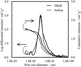
The thickness, pore size distribution, and WU of both SBuH and Nafion® CLs were measured as representative parameters that affect the oxygen transport resistance of the CLs, in terms of the diffusion length, the Knudsen diffusion, and the amount of adsorbed water. The thickness of the SBuH and Nafion® CLs was found to be 6.3 ± 0.3 μm and 6.8 ± 1.1 μm, respectively, by scanning electron microscopy. Fig. 4 shows the pore size distribution of both cathode CLs, determined using a mercury intrusion system. A single distribution peak was seen for both the SBuH and Nafion® CLs, at 36 nm and 33 nm, respectively. Both the pore size distribution and the total pore volume in the SBuH CLs were comparable to those of the Nafion® CLs. Thus, it was considered that the Knudsen diffusion and the oxygen transport resistance in the CLs might be equivalent in both CLs under dry conditions. The WU of SBuH and Nafion® CLs was measured at 80 °C as the RH was increased from 10% RH to 90% RH (Fig. S4†). The WU of SBuH CLs matched that of the Nafion® CLs at high RH, and their humidity dependency qualitatively agreed with expectations from the values of λ in the membranes. Under conditions of 80 °C and 90% RH, the WU values of SBuH and Nafion® CLs were 50 wt% and 47 wt%, respectively. These results suggested that a comparable amount of water was present in the SBuH and Nafion® CLs under conditions of high humidity. These results, along with the structure of the CLs, indicate that the contribution of water adsorbed in the pores of the CLs to the oxygen transport resistance was equivalent for SBuH and Nafion®.
The oxygen reduction reaction limiting current was measured at 80 °C and 90% RH under varying operating pressures and oxygen concentrations to investigate the oxygen transport resistance in the cathodes. Fig. 5 shows the polarization curves at 101.3 kPa with various oxygen concentrations (2.6%, 1.8%, 0.79%, and 0.53%). The value of the limiting current was observed at 0.20 V vs. the RHE, and was found to be comparable for SBuH and Nafion® CLs regardless of the oxygen concentration. The oxygen transport resistance in the CLs was calculated by subtracting the oxygen transport resistance in the gas diffusion layers and the microporous layers from the total resistance.31–33 The SBuH CLs showed low oxygen gas transport resistance, which was comparable to that of the Nafion® CLs (Fig. S3†). However, membrane electrode assemblies (MEAs) composed of sulfonated polyaromatic ionomers without aliphatic side chains showed higher oxygen transport resistance.34 Considering the results of the oxygen transport resistance, pore structure, and WU of the SBuH ionomer-based CLs, we conclude that oxygen permeability of SBuH is comparable to Nafion® ionomers.
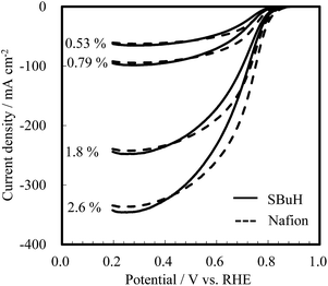 | ||
| Fig. 5 Oxygen reduction reaction limiting current of SBuH and Nafion® CLs under various oxygen concentrations at 101.3 kPa. | ||
Fuel cell tests of MEAs composed of the SBuH and Nafion® CLs were performed to evaluate the oxygen transport properties in the SBuH CLs at high current density, with an increase in the amount of produced water. Nafion® NR-211 membranes were used as the electrolytes, and the tests were conducted at 80 °C and 90% RH. A back-pressure of 200 MPa and an atmosphere of hydrogen and oxygen, air, or 10% oxygen was used. The I–V curves in Fig. 6 show that the cell voltage of the SBuH CLs was lower than that of the Nafion® CLs at high current density. On the other hand, the SBuH CLs showed an equivalent cell voltage to the Nafion® CLs when the oxygen concentration was decreased. These results agreed with the tendency of the ORR limiting current observed at 0.20 V vs. the RHE. The SBuH CLs showed comparable oxygen permeability and performance to the Nafion® ionomers, regardless of the amount of water produced. The cell resistances of the SBuH-based MEAs were slightly higher than those of the Nafion®-based MEAs regardless of the current density. The increase in the cell resistance might be due to the increase of the proton transport resistance, the electronic resistance, and/or the resistance between the Nafion® NR-211 membranes and CLs. To the best of our knowledge, these SBuH ionomers are the first example of hydrocarbon-based ionomers with a performance that is equivalent to that of perfluorinated ionomers.
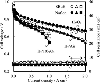 | ||
| Fig. 6 I–V curves of SBuH and Nafion® CLs at 80 °C and 100% RH under 200 kPa with hydrogen and oxygen, air, or 10% oxygen supply. | ||
In conclusion, a sulfonated diblock copolymer having aliphatic side chains on the p-phenylene backbone was applied as a cathode ionomer in a PEMFC. SBuH membranes showed gas permeability coefficients that were equivalent to those of Nafion® membranes under highly humid conditions because of the plasticizing effects of the aliphatic side chains of SBuH. CLs composed of SBuH ionomers also showed equivalent oxygen transport properties to Nafion® ionomers, regardless of the amount of the produced water. The thickness, pore size distribution, and WU values were also comparable for the SBuH and Nafion® CLs. We demonstrated that the addition of aliphatic side chains to the polymer backbone is a promising strategy to improve the oxygen transport properties of ionomers used in CLs. The increased understanding of the links between the chemical structure of the diblock copolymer, the electrochemical properties of the CLs, and the chemical durability of the diblock copolymer under fuel cell conditions will lead to future strategies for the molecular design of CL ionomers.
Acknowledgements
This work is a part of the Strategic Development of PEFC Technologies for Practical Application project, by the New Energy and Industrial Technology Development Organization (NEDO), Japan.Notes and references
- S. A. Eastman, S. Kim, K. A. Page, B. W. Rowe, S. Kang, C. L. Soles and K. G. Yager, Macromolecules, 2012, 45(19), 7920 CrossRef CAS.
- J. Zhang, H. A. Gasteiger and W. Gu, J. Electrochem. Soc., 2013, 160(6), F616 CrossRef CAS.
- A. Albert, T. Lochner, T. J. Schmidt and L. Gubler, ACS Appl. Mater. Interfaces, 2016, 8(24), 15297 CAS.
- D. W. Shin, M. D. Guiver and Y. M. Lee, Chem. Rev., 2017, 117(6), 4759 CrossRef CAS PubMed.
- M. Lee, J. K. Park, H. S. Lee, O. Lane, R. B. Moore, J. E. McGrath and D. G. Baird, Polymer, 2009, 50, 6129 CrossRef CAS.
- H. D. Moore, T. Saito and M. A. Hickner, J. Mater. Chem., 2010, 20, 6316 RSC.
- Y. Chang, G. F. Brunello, J. Fuller, M. Hawley, Y. S. Kim, M. Disabb-Miller, M. A. Hickner, S. S. Jang and C. Bae, Macromolecules, 2011, 44, 8458 CrossRef CAS.
- K. Nakabayashi, T. Higashihara and M. Ueda, Macromolecules, 2011, 44, 1603 CrossRef CAS.
- Y. Chang, A. D. Mohanty, S. B. Smedley, K. Abu-Hakmeh, Y. H. Lee, J. E. Morgan, M. A. Hickner, S. S. Jang, C. Y. Ryu and C. Bae, Macromolecules, 2015, 48, 7117 CrossRef CAS.
- T. Mochizuki, M. Uchida and K. Miyatake, ACS Energy Lett., 2016, 1, 348 CrossRef CAS.
- Y. Zhao, M. Yoshida, T. Oshima, S. Koizumi, M. Rikukawa, N. Szekely, A. Radulescu and D. Richter, Polymer, 2016, 86, 157 CrossRef CAS.
- J. Peron, D. Edwards, A. Besson, Z. Shi and S. Holdcroft, J. Electrochem. Soc., 2010, 157, B1230 CrossRef CAS.
- R. W. Lindström, A. Oyarce, L. G. Aguinaga, D. Ubeda, M. Ingratta, P. Jannasch and G. Lindbergh, J. Electrochem. Soc., 2013, 160, F269 CrossRef.
- T. Yoda, T. Shimura, B. Bae, K. Miyatake, M. Uchida, H. Uchida and M. Watanabe, Electrochim. Acta, 2009, 54, 4328 CrossRef CAS.
- C. Lei, D. Bessarabov, S. Ye, Z. Xie, S. Holdcroft and T. Navessin, J. Power Sources, 2011, 196, 6168 CrossRef CAS.
- D. Novitski and S. Holdcroft, ACS Appl. Mater. Interfaces, 2015, 7, 27314 CAS.
- D. K. Paul and K. Karan, J. Phys. Chem. C, 2014, 118, 1828 CAS.
- Y. C. Park, K. Kakinuma, H. Uchida, M. Watanabe and M. Uchida, J. Power Sources, 2015, 275, 384 CrossRef CAS.
- A. Strong, B. Britton, D. Edwards, T. J. Peckham, H. F. Lee, W. Y. Huang and S. Holdcroft, J. Electrochem. Soc., 2015, 162, F513 CrossRef CAS.
- K. Umezawa, T. Oshima, M. Yoshizawa-Fujita, Y. Takeoka and M. Rikukawa, ACS Macro Lett., 2012, 1, 969 CrossRef CAS.
- Y. Takeoka, K. Umezawa, T. Oshima, M. Yoshida, M. Yoshizawa-Fujita and M. Rikukawa, Polym. Chem., 2014, 5, 4132 RSC.
- Y. Fan, C. J. Cornelius, H. S. Lee, J. E. McGrath, M. Zhang, R. Moore and C. L. Staiger, J. Membr. Sci., 2013, 430, 106 CrossRef CAS.
- B. Bae, K. Miyatake and M. Watanabe, J. Membr. Sci., 2008, 310, 110 CrossRef CAS.
- B. Bae, K. Miyatake and M. Watanabe, Macromolecules, 2010, 43, 2684 CrossRef CAS.
- S. Seesukphronrarak and A. Ohira, Chem. Commun., 2009, 4744 RSC.
- S. Seesukphronrarak, K. Ohira, K. Kidena, N. Takimoto, C. Seiti and A. Ohira, Polymer, 2010, 51, 623 CrossRef CAS.
- S. Holdcroft, Chem. Mater., 2014, 26(1), 381 CrossRef CAS.
- A. Ohma, T. Mashio, K. Sato, H. Iden, Y. Ono, K. Sakai, K. Akizuki, S. Takaichi and K. Shinohara, Electrochim. Acta, 2011, 56, 10832 CrossRef CAS.
- J. Kawaji, S. Suzuki, Y. Takamori, T. Mizukami and M. Morishima, J. Electrochem. Soc., 2011, 158(8), B1042 CrossRef CAS.
- T. Nakajima, T. Tamaki, H. Ohashi and T. Yamaguchi, J. Phys. Chem. C, 2012, 116, 1422 CAS.
- T. Mashio, A. Ohma, S. Yamamoto and K. Shinohara, ECS Trans., 2007, 11, 529 CAS.
- Y. Ono, A. Ohma, K. Shinohara and K. Fushinobu, J. Electrochem. Soc., 2013, 160(8), F779 CrossRef CAS.
- N. Nonoyama, S. Okazaki, A. Z. Weber, Y. Ikogi and T. Yoshida, J. Electrochem. Soc., 2011, 158, B416 CrossRef CAS.
- S. Sambandam, J. Parrondo and V. Ramani, Phys. Chem. Chem. Phys., 2013, 15, 14994 RSC.
Footnote |
| † Electronic supplementary information (ESI) available: Materials and method for the preparation of membranes and catalyst layers. Measurement conditions for membranes, characterizations, and fuel cell tests. See DOI: 10.1039/c7se00167c |
| This journal is © The Royal Society of Chemistry 2017 |


