
 Open Access Article
 This Open Access Article is licensed under a Creative Commons Attribution-Non Commercial 3.0 Unported Licence
A combined experimental and theoretical spectroscopic protocol for determination of the structure of heterogeneous catalysts: developing the information content of the resonance Raman spectra of M1 MoVOx†
Adam
Kubas
ad,
Johannes
Noak
bc,
Annette
Trunschke
 *b,
Robert
Schlögl
*ab,
Frank
Neese
*a and
Dimitrios
Maganas
*a
*b,
Robert
Schlögl
*ab,
Frank
Neese
*a and
Dimitrios
Maganas
*a
aMax-Planck Institute for Chemical Energy Conversion, Stiftstrasse 34–36, D-45470 Mülheim an der Ruhr, Germany. E-mail: frank.neese@cec.mpg.de; dimitrios.manganas@cec.mpg.de
bInorganic Chemistry Department, Fritz-Haber-Institut der Max-Planck Gesellschaft, Faradayweg 4-6, 14195 Berlin, Germany. E-mail: trunschke@fhi-berlin.mpg.de
cBasCat-UniCat BASF Jointlab, Technische Universität Berlin, Hardenbergstrasse 36, 10623 Berlin, Germany
dInstitute of Physical Chemistry, Polish Academy of Sciences, Kasprzaka 44/52, 01-224 Warsaw, Poland
First published on 30th June 2017
Abstract
Absorption and multiwavelength resonance Raman spectroscopy are widely used to investigate the electronic structure of transition metal centers in coordination compounds and extended solid systems. In combination with computational methodologies that have predictive accuracy, they define powerful protocols to study the spectroscopic response of catalytic materials. In this work, we study the absorption and resonance Raman spectra of the M1 MoVOx catalyst. The spectra were calculated by time-dependent density functional theory (TD-DFT) in conjunction with the independent mode displaced harmonic oscillator model (IMDHO), which allows for detailed bandshape predictions. For this purpose cluster models with up to 9 Mo and V metallic centers are considered to represent the bulk structure of MoVOx. Capping hydrogens were used to achieve valence saturation at the edges of the cluster models. The construction of model structures was based on a thorough bonding analysis which involved conventional DFT and local coupled cluster (DLPNO-CCSD(T)) methods. Furthermore the relationship of cluster topology to the computed spectral features is discussed in detail. It is shown that due to the local nature of the involved electronic transitions, band assignment protocols developed for molecular systems can be applied to describe the calculated spectral features of the cluster models as well. The present study serves as a reference for future applications of combined experimental and computational protocols in the field of solid-state heterogeneous catalysis.
Introduction
Over the past few decades, chemistry has witnessed an increasing interest in alkane reactivity as the chemical industry is preparing for the changeover from oil feedstock to other sources for alkanes as the basis for the production of functionalized small molecules.1 Moreover, utilization of short-chain alkanes via direct oxidation would help to save energy by avoiding high-temperature steam cracking technologies. In this respect, high selectivity in oxidation reactions is desirable in terms of the sustainable use of resources. Currently, there are two major industrial activities including (a) oxidative dehydrogenation of alkanes to olefins such as ethene, propene and, though in much less quantities, butene2 and (b) selective (amm)oxidation of alkanes to oxygenated products, such as butane to maleic anhydride,3 as well as the synthesis of acrylonitrile, acrylic acid, or methylmethacrylate.4Multi-metallic oxide networks are active components in catalysis for selective oxidation of alkanes as they provide the best compromise between selectivity and site isolation.5–8 Hence, complex oxides have been synthesized to establish site isolation on a structural basis. In particular molybdenum–vanadium based multimetal oxide catalysts are considered among the most versatile catalysts in the selective oxidation of ethane,9 propane10 and propene.11 This type of heterogeneous catalyst offers a great opportunity to tackle structure–function relationships in complex oxidation reactions. In fact, the multifunctionality and site selectivity of this class of catalysts has been explored both experimentally and theoretically in various oxidation reactions.5,12–23 It has been shown, however, that under reaction conditions the catalyst surface is structurally different from the bulk and highly dynamic with respect to changes in the composition of the surrounding gas phase.5 Therefore, establishing key structure–reactivity relationships is a highly desirable task to rationally design catalysts for selective oxidation. This requires the execution of systematic spectroscopic investigations into structural, electronic and surface properties of the catalysts.
In order to shed more light on the structural basis for selective oxidation conditions, it is necessary to develop the full information content of spectra taken under operation. In general, the more spectroscopic information using various spectroscopic techniques is available, the more reliable the derived structure/activity relationships will be. This practice has been proven to be of paramount importance in the cases of supported vanadia and molybdena catalysts.24–26 However, we have shown recently27 that it is difficult to arrive at safe conclusions unless combined experimental and theoretical protocols that involve (a) state of the art experimental techniques such as multiwavelength Raman and multimetal soft X-ray spectroscopy and (b) theoretical methods with strong predictive performance are applied in combination. In fact, combined experimental and theoretical multi-method protocols have been used to great advantages in (bio)inorganic chemistry and catalysis to unravel otherwise unknown structural topologies in enzymes28–30 (e.g. the identification of a unique carbide center in the active site of the dinitrogen activating enzyme nitrogenase31), or in clarifying the structure32 and oxidation states33 of the oxygen evolving complex in photosynthesis.
As an example of structure to spectroscopic response correlation, we present here a combined experimental and computational multiwavelength Raman study of the semi-crystalline M1 phase of MoVOx oxide catalysts representing an intermediate in synthesis and a model of the working catalyst. This compound is considered as a basic structure for the catalytically related MoVNbTeOx variant. In the present work, we were interested in exploring the possibility of comparing the spectroscopic properties of the final compound sub-group structures (motifs) that would allow the representation of these structures like a jigsaw puzzle. In particular, 2D and 3D structures were constructed from monomeric and dimeric building units. More specifically, construction of the dimeric 3D model structures was performed on the basis of potential energy surfaces (PESs) along the normal modes connecting the corresponding monomeric structures at the domain-based local pair natural orbital coupled-cluster theory with single, double and perturbative triple excitation levels of theory (DLPNO-CCSD(T)).34 This method has in fact provided excellent energetics on molecular systems35–37 and extended surfaces.38 The 2D and 3D designed structures were further evaluated for their ability to predict the observed absorption and rRaman spectra. Future design concepts as well as studies of the synthesis of these compounds would benefit from such a step-by-step approach.
MoVOx synthesis
As described recently39 the MoV oxide was synthesized hydrothermally. Ammonium heptamolybdate (Merck, 11.75 g; 66.5 mmol Mo) and vanadyl sulfate (Acros Organics, 4.01 g; 15.8 mmol) were dissolved in 230 ml and 30 ml of water, respectively, and mixed together at 40 °C under vigorous stirring. The solution was then transferred to an autoclave (Premex Reactor AG, Lengnau, Switzerland) made from corrosion resistant Hastelloy C-22 (2.4602). The vessel was heated to 150 °C at a rate of 1 °C min−1 and held at this temperature for 100 h. The reaction mixture was stirred during the whole experiment at a rate of 100 rpm. The resulting solid was isolated by filtration using a glass frit (pore size 5), washed with water, and dried at 80 °C giving 3.7 g of a fine black powder (internal ID 15285). Thereafter, the solid was thermally treated at 400 °C (heating rate 10 °C min−1) in flowing argon (flow rate 100 ml min−1) for 2 h in a rotary tube furnace (Xerion, Freiberg, Germany, internal ID 15342).UV/vis spectroscopy
The UV-vis spectra were recorded in reflectance using an Agilent Cary 5000 instrument equipped with an in situ cell (Harrik Praying Mantis™ diffuse reflectance attachment DRP-SAP in combination with a HVC-VUV reaction chamber). Spectra were presented in the Kubelka–Munk function (F(R)). Spectralon was used as a white reference.Raman spectroscopy
Raman measurements of the MoVOx sample have been conducted using a confocal microscope system (S&I Spectroscopy & Imaging GmbH) with a monochromator (Princeton Instruments, 750 mm focal length) equipped with a UV enhanced CCD camera (PyLoN:2kBUV). The Raman spectra were obtained under resonance or near resonance conditions using a variety of individual lasers operating at 532 nm, 488 nm, 442 nm, 355 nm, 325 nm and 266 nm excitation frequencies, respectively. Special care was taken in order to minimize the beam damage by adjusting the energy density on the sample and using different irradiated spots in consecutive measurements. When the 532 nm laser was used, ×10 objective, 600 g mm−1 grating, and filters ND = 1.4–1.8 were applied resulting in a laser power between 0.5 and 0.2 mW at the sample. The exposure time was 300 s. The measurement using the 325 nm laser was performed applying a UVB objective, 2400 g mm−1 grating and filters ND = 0.7, 1.1, and 1.2, respectively, resulting in a laser power between 0.44 and 0.14 mW. The exposure time was 1800 s.Computational details
All calculations were performed with the ORCA suite of programs, version 3.0.3.40 Throughout, the density functional theory (DFT) calculations were carried out in a spin unrestricted formalism with the B3LYP functional together with Grimme’s dispersion correction.41,42 Low spin open shell systems were treated within the broken-symmetry DFT framework. The calculations were accelerated by employing the resolution of identity approximation (RI)43 for the Coulomb integrals, while the exchange terms were efficiently computed using the ‘chain-of-spheres exchange’ (COSX) approach.44 Scalar relativistic effects were taken into account using the second order Douglas–Kroll–Hess approach (DKH).45–47 For all atoms, we employed segmented all-electron relativistically contracted basis sets of triple-ζ quality (TZV-DKH).48 These basis sets are closely related to the original def2-TZVP basis49 but provide greater flexibility in the core region and feature relativistically determined contraction coefficients. The corresponding decontracted def2-TZVP/J basis50 was used as an auxiliary basis set for the RI approximation. Truncated models were obtained from the crystal structure. Whenever a cut was taken through a metal–oxygen (M–O) bond, the free valence of the oxygen atom was saturated with a hydrogen atom placed along the M–O bond. The O–H bond length was set to a typical value of 0.96 Å. The calculations were performed with the large grid 5 and the RIJCOSX approximation used the numerical grid 6 in ORCA nomenclature. The ground state energies were converged to 10−9 hartree. For the dimeric model structures, potential energy surfaces (PESs) along normal modes were constructed at the DLPNO-CCSD(T) level.34 The calculated energies were extrapolated to the complete basis set limit (CBS) by applying the well-known two point extrapolation with the all electron def2-TZVPP/def2-QZVPP49 basis sets.51,52 Potential energy curves along the stretching vibrational modes connecting the V and Mo based monolayer structures were constructed and plotted in a diagram (Fig. 6) of energy versus distances. The excited state calculations were carried out within time-dependent DFT53 in the Tamm–Dancoff approximation54,55 and accounted for 50–100 excited states for each model in order to ensure that the observed spectra range is properly covered. The independent mode displaced harmonic oscillator (IMDHO) model approach40,56–59 as implemented in ORCA was used for the calculation of the absorption bandshapes as well as the resonance Raman profiles. In this approach, only linear terms in the difference between the excited and ground state vibrational Hamiltonians are taken into account. Higher order terms, namely, anharmonic effects as well as Duschinsky mixing and frequency changes between the excited and ground vibrational Hamiltonians, are omitted. Although at least to some extent this might lead to deficiencies in the energetic positions and relative intensities of particular calculated rRaman bands with respect to the experiment, this approach has shown great performance in describing the rRaman spectra of systems ranging from organic molecules to transition metal compounds and solid systems.27,58,59 The absorption as well as the resonance Raman spectra were generated using the orca_asa utility.58,59 In this concept the effective band broadening parameters are related to the Cartesian gradients of the excited states energies. This approach is to be preferred over simply broadening calculated vertical transitions with Gaussian peaks.Geometric structure
The structure of the M1 MoVOx catalyst is visualized in Fig. 1. As is commonly observed in M1 type structures, the MoVOx building units are composed of corner and edge sharing MO6 polyhedra (M = Mo-purple, V-cyan). A prominent feature is a network of corner-sharing MO6 octahedra forming a planar network. In the ab plane, monolayers are built up by the addition of oxygen bridged pentagonal pillars containing MO5 building units defining a two-dimensional (2D) network. Moreover, the combination of the octahedra and the pentagonal bipyramids creates a two-dimensional space-filling network containing hexagonal and heptagonal voids resulting in 2D network structures. Furthermore, the above network can be extended along the third dimension in which the monolayer surfaces are stacked via metal–oxygen interlayer interactions. This complex structure provides a highly anisotropic coordination environment around the vanadium and molybdenum centers which is also reflected in the spread of the M–O bond distances. In the ab plane “in plane”, a two-dimensional network is composed by terminal V/Mo–O bonds and V–O–V, Mo–O–Mo and Mo–O–V bridging units. The typical Mo–O and V–O bonds involving bridging O-atoms range between 1.78 and 2.02 Å, while the corresponding out of plane V–O and Mo–O bond lengths range between 1.62 and 1.76 Å. This is in close agreement with typical terminal vanadyl and molybdenyl (Mo![[double bond, length as m-dash]](https://www.rsc.org/images/entities/char_e001.gif) O, VO) bond lengths according to the Cambridge crystallographic database for V/MoOx isolated clusters.60 In fact, as can be seen in Fig. 2, in the case of V–O bond lengths a statistical search of over 1500 structures from the Cambridge crystallographic database reveals that typical VO double bonds are observed at 1.60 Å while typical single V–O bonds are observed between 1.80 and 1.92 Å. Larger bond lengths are always found in 3D structures containing OV⋯O bridging units along the third dimension. Similar arguments can be drawn for the respective Mo based centers. We further apply the above bond-length arguments to describe the topologies of the M1 MoVOx structure. In agreement with the structural description provided above by inspecting the bond lengths of the M1 MoVOx structures, it becomes evident that both 2D and 3D topologies can be identified. In particular, the 2D topologies contain vanadia and molybdena centers in four and five-fold coordination environments which are constructed by VO(O)4, MoO(O)4 and MoO(O)5 building units in order to describe the terminal V–O and Mo–O bonding as well as the VO and MoO bonding around the metal centers. Likewise, 3D structures refer to six and seven-fold coordination environments which are constructed by VO(O4)O and MoO(O5)O building units. In this view the monolayer VO(O)4, MoO(O)4 and MoO(O)5 units are separated by OM⋯O bonding interactions which range between 2.25 and 2.35 Å for M = Mo and V, respectively. In the theoretical section the energetic preference of the 2D and 3D topologies as well as their impact to the calculated spectra will be evaluated.
O, VO) bond lengths according to the Cambridge crystallographic database for V/MoOx isolated clusters.60 In fact, as can be seen in Fig. 2, in the case of V–O bond lengths a statistical search of over 1500 structures from the Cambridge crystallographic database reveals that typical VO double bonds are observed at 1.60 Å while typical single V–O bonds are observed between 1.80 and 1.92 Å. Larger bond lengths are always found in 3D structures containing OV⋯O bridging units along the third dimension. Similar arguments can be drawn for the respective Mo based centers. We further apply the above bond-length arguments to describe the topologies of the M1 MoVOx structure. In agreement with the structural description provided above by inspecting the bond lengths of the M1 MoVOx structures, it becomes evident that both 2D and 3D topologies can be identified. In particular, the 2D topologies contain vanadia and molybdena centers in four and five-fold coordination environments which are constructed by VO(O)4, MoO(O)4 and MoO(O)5 building units in order to describe the terminal V–O and Mo–O bonding as well as the VO and MoO bonding around the metal centers. Likewise, 3D structures refer to six and seven-fold coordination environments which are constructed by VO(O4)O and MoO(O5)O building units. In this view the monolayer VO(O)4, MoO(O)4 and MoO(O)5 units are separated by OM⋯O bonding interactions which range between 2.25 and 2.35 Å for M = Mo and V, respectively. In the theoretical section the energetic preference of the 2D and 3D topologies as well as their impact to the calculated spectra will be evaluated.
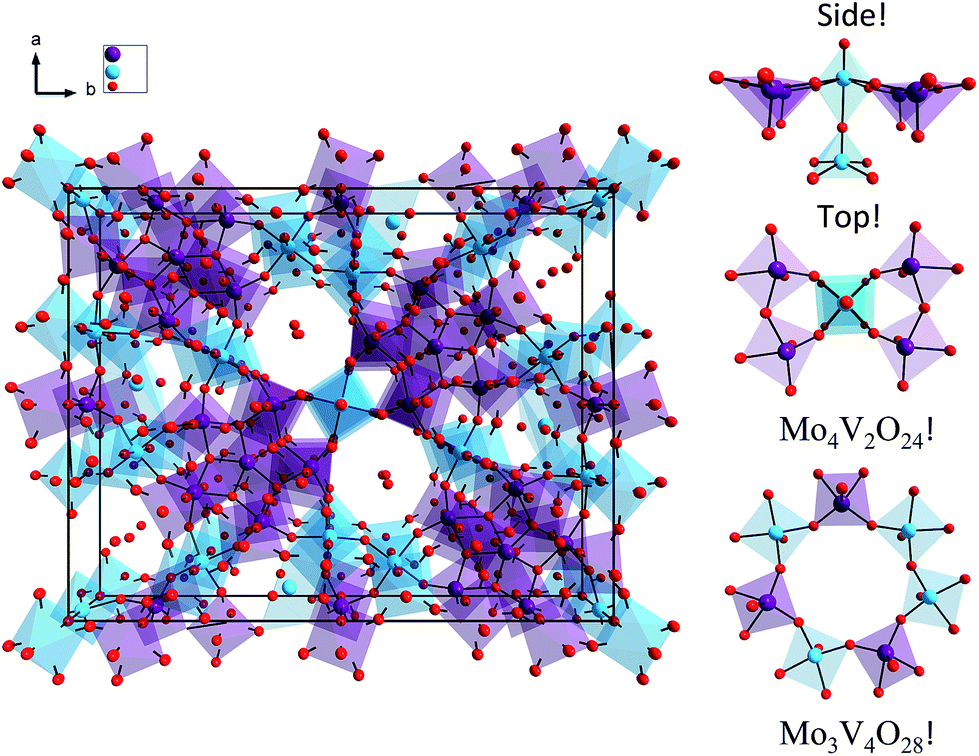 | ||
| Fig. 1 (Left) Molecular structure of the M1 MoVOx catalyst. (Right) Molecular topologies dominating the spectroscopic response catalyst. Color coding: O red, V cyan, Mo purple. | ||
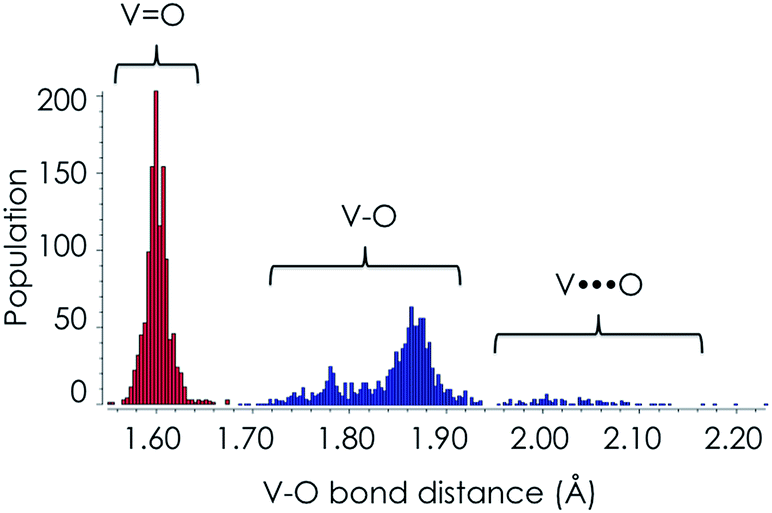 | ||
| Fig. 2 A statistical evaluation of the V–O bond lengths according to the data from the Cambridge crystallographic database. | ||
Optical and rRaman spectroscopy
The absorption spectrum from an amorphous (semi-crystalline) MoVOx sample is presented in Fig. 3. It is characterized by three well-distinguished features centered at 18![[thin space (1/6-em)]](https://www.rsc.org/images/entities/char_2009.gif) 000, 30000 and 38000 cm−1. At higher energies, around 45000 cm−1, one finds an additional intense feature that is less well defined owing to detector saturation. As is seen in Fig. 3, a Gaussian fit to the absorption spectrum requires 5 Gaussian bands: [1] (blue, 18000 cm−1), [2] (cyan, 27000 cm−1), [3] (dark red, 32000 cm−1), [4] (orange, 40000 cm−1) and [5] (gray, 46000 cm−1).
000, 30000 and 38000 cm−1. At higher energies, around 45000 cm−1, one finds an additional intense feature that is less well defined owing to detector saturation. As is seen in Fig. 3, a Gaussian fit to the absorption spectrum requires 5 Gaussian bands: [1] (blue, 18000 cm−1), [2] (cyan, 27000 cm−1), [3] (dark red, 32000 cm−1), [4] (orange, 40000 cm−1) and [5] (gray, 46000 cm−1).
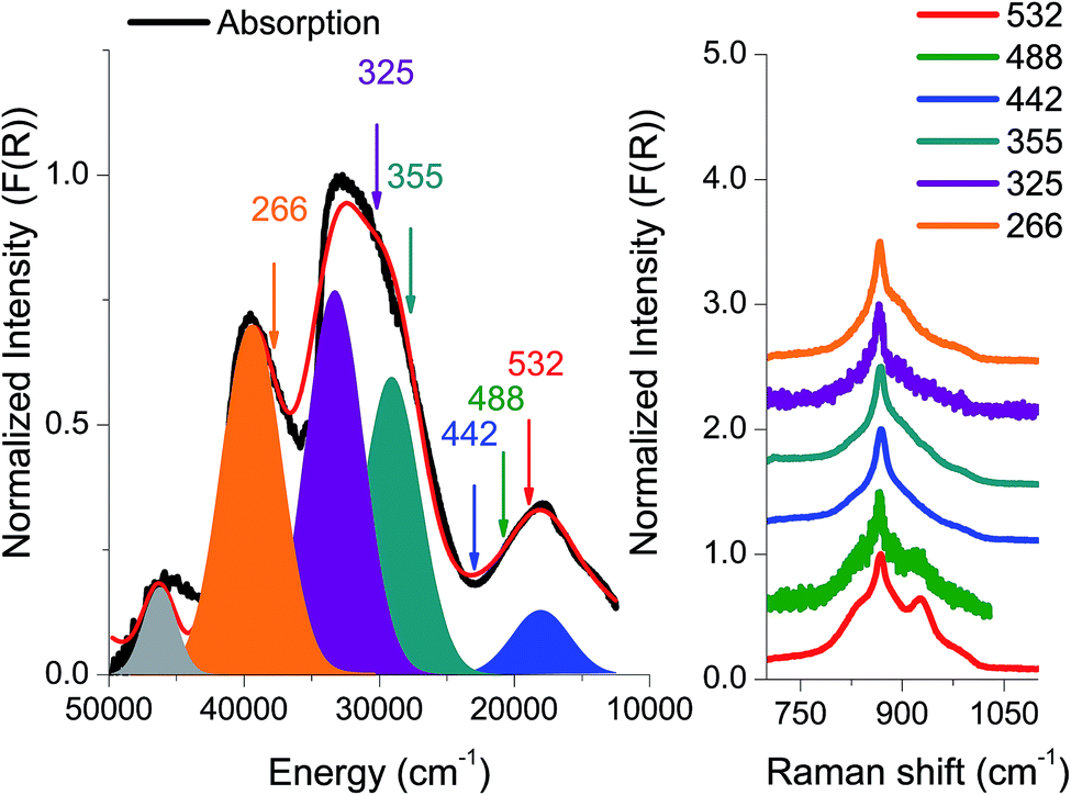 | ||
| Fig. 3 Experimental absorption spectrum (black) together with the respective rRaman spectra recorded at the pointed excitations (266, 325, 355, 442, 488 and 532 nm). All spectra are presented in normalized Kubelka–Munk (F(R)) units. The red absorption spectrum represents a Gaussian fit to the experimental spectrum with a minimum of five individual bands (represented by filled Gaussians). | ||
This spectral envelope deviates substantially from the broad and unresolved spectra of vanadia and molybdena oxides VxOy and MoxOy with oxidation states 5 and 6 in pure or supported form.61–63 Furthermore, it should be noted that the observed bandwidth is very similar to the absorption spectra typically observed for mononuclear oxo–vanadia (V) complexes.27
In an effort to obtain further information with respect to the nature of these dominating transitions, resonance Raman (rR) spectroscopy was applied. The rR spectra were recorded at six laser frequencies, namely 18797 cm−1 (532 nm), 20491 cm−1 (488 nm), 22624 cm−1 (442 nm), 29850 cm−1 (355 nm), 30770 cm−1 (325 nm) and 37594 cm−1 (266 nm). As can be seen in Fig. 3, the rR spectra corresponding to the chromophore around 20000 cm−1 (lasers 532, 488, and 442 nm) have characteristic shapes with high intensity features located at 850 and 950 cm−1 and a shoulder at 800 cm−1. Moreover, by shifting the excitation wavelength to higher energies, the 850 and 950 cm−1 rR signals lose intensity. Furthermore, the corresponding rR spectra with excitation into the 30000 and 38000 cm−1 absorption bands (excitation wavelengths 355, 325 and 266 nm) show similar rR signals characterized by a sharp signal located at 850 cm−1 with broad tails observed between 750 and 1050 cm−1.
An assignment of all spectral features observed in the UV/vis and rR experiments will be developed below on the basis of detailed electronic structure calculations.
Theoretical calculations
Construction of model structures
The model structures to mimic the local environments of the M1 MoVOx catalyst were constructed by employing the capping hydrogen saturation technique.64–66 This technique has been widely applied to construct cluster models for the calculation of X-ray spectra of strongly covalent metal oxides such as TiO2, V2O5, Si/VxOy and Si/MoxOy,64,67–71 where it has shown satisfactory performance in the sense that the computed spectra converged to a bulk-limit upon extension of the cluster model.24,65,66,72 In contrast to those examples the present study is substantially more demanding as the structure is non-dense and thus no arbitrary motifs can be chosen as in dense structures. In the present study we made an effort to capture both surface and bulk properties influencing the absorption as well as the rRaman spectra through the following series of monomeric and dimeric structures of VO(OH)5, MoO(OH)5 and MoO(OH)6, VOV_ax: V2O10H8, VOV_eq: V2O9H6, MoOMo_ax1: Mo2O10H8, MoOMo_ax2: Mo2O12H10, MoOMo_eq: Mo2O9H6 and MoOV_eq: MoVO9H6 (Fig. 4). Moreover, the structural motifs will be represented by the mono-layered cluster models 1a: Mo4VO19H10, 2a: Mo4V3O28H18, 3: Mo3V4O28H18 and 4a: Mo6O21H10 as well as the bilayer cluster models 1b: Mo4V2O24H14, 2b: Mo5V4O36H24 and 4b: Mo7O26H20 (Fig. 5). | ||
| Fig. 4 Monomeric and dimeric model structures of VO(OH)5, MoO(OH)5, VOV_ax: V2O10H8, VOV_eq: V2O9H6, MoOMo_ax: Mo2O10H8, MoOMo_eq: Mo2O9H6 and MoOV_eq: MoVO9H6 (color coding: Mo, purple, V, cyan, O, red, H, white). | ||
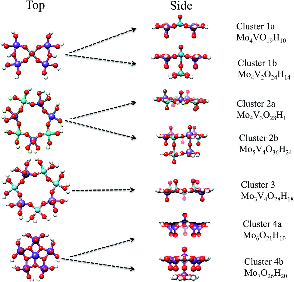 | ||
| Fig. 5 Top and side view of the hydrogen saturated cluster models used to model the MoV topologies of the MoVOx catalyst. In particular, mono-layered clusters 1a: Mo4VO19H10, 2a: Mo4V3O28H18, 3: Mo3V4O28H18 and 4a: Mo6O21H10 as well as bilayer 1b: Mo4V2O24H14, 2b: Mo5V4O36H24 and 4b: Mo7O26H20 are visualized (color coding: Mo, purple, V, cyan, O, red, H, white). | ||
The crystal structure of the M1 MoVOx catalysts contains multiple dimeric contacts of the type M–O–M (M = Mo, V). Hence in a first step of our analysis we consider simple monomeric and dimeric model structures, presented in Fig. 4, which will be used in the following to correlate the calculated spectroscopic properties with the electronic structure and the coordination environment surrounding the metal centers.
In a further step we consider larger aggregates through cluster models, as shown in Fig. 5, for which we will perform a detailed comparison between theory and experimental spectroscopic properties.
Cluster 1a represents a hydrogen-saturated version of the crystallographically observed topology composed of V–O–Mo and Mo–O–Mo bridged VO(O)4 and MoO(O4) units in a 1:4 ratio. Cluster 1b represents a local defect structure of cluster 1a in which the bilayer (out of plane) OV⋯OV motif is taken into account along the third dimension. In particular, one of the vanadia centers obtains a locally distorted VO(O)5 coordination environment. Cluster 2a describes a hydrogen-saturated version of the crystallographic cyclic topology composed of in plane V–O–Mo and Mo–O–Mo bridged VO(O)4 and MoO(O4) units in a 3:4 ratio. In a similar manner to cluster 1b, cluster 2b represents a 3D defect structure of cluster 2a in which the weakly linked bilayer (out of plane) OV⋯OV and OMo⋯OMo building units are taken into account along the third dimension. Cluster 3 represents an alternative 2D defect structure of cluster 2a in which one of the Mo centers has been replaced by V. As a result cluster 3 features in-plane V–O–Mo and V–O–V bridged VO5 and MoO5 units in a 4:3 ratio. Finally, cluster 4a and 4b represent 2D and 3D cluster representations constructed by pentagonal pillar MoO(O)5 units consisting solely of MoO centers. We should emphasize that although other cluster models could also be considered including additional variations from the pentagonal MoO(O)5, as well as the hexagonal and heptagonal MoxVyOz building units, the present choice generates a representative sample of topologies that will be used in order to establish structure/spectra correlations. We will show in particular that the choice of the 2D and most importantly the 3D structural units as those shown in Fig. 4 and 5 is entirely justified.
Metal oxidation states
Prior to the investigation of the electronic structure and the spectroscopic properties of the M1 phase of the MoVOx catalyst it is necessary to examine the local metal oxidation states of the involved metallic centers. It should be emphasized that the formal oxidation states of the Mo and V centers in the M1 phase of the MoVOx catalysts can vary between VI–V and V–IV, respectively, depending on the catalyst preparation procedure as well as treatment prior to reaction.39,73–76 In particular, molybdenum centers show preference for Mo(VI)Ox sites while vanadia centers are rather sensitive in this respect, providing mixed valence admixtures V(V/IV)Ox of variable compositions. In the case of the M1 MoVOx catalyst synthesized by vanadyl sulfate, the monomeric building VO(O5) units can be thought of as partially oxidized units of the initial V(IV)O(O4) centers due to the formation of interlayer OM⋯O bonding interactions. Hence the vanadium centers can be viewed as consisting of vanadyl(V)–oxo (O⋯V(V)O) or vanadyl(IV)–oxyl (O⋯V(IV)–O) species. Since both types of species have the same electron count, the differentiation may appear to be semantic. However, considerations of this type have been proven instrumental in rationalizing the nature of the reactive intermediates in high valent iron systems.28–30 With all of this in mind we have investigated the above possibilities for all of the chosen model structures by means of unrestricted Kohn–Sham and broken-symmetry DFT calculations. In all cases, pure singlet states were obtained reflecting V(V)Ox monomeric centers and oligomeric vanadium centers. In addition, the alternative scenario involving isolated V(IV)Ox or antiferromagnetically coupled V(IV)–O–V(IV) species was investigated. The latter was not found to be favored over the former, while the lack of experimental evidence of isolated V(IV)Ox surface or bulk species led us to exclude this possibility from the present study. In particular, at the B3LYP level the V(IV)Ox species were found to be unstable with respect to the V(V)Ox species by ∼10 kcal mol−1. Similarly V(IV)–O–V(IV) and O⋯V(IV)–O motifs were found to be unstable by 9 and 12 kcal mol−1, respectively, in comparison to the V(V)–O–V(V) and O⋯V(V)O ones. Under reaction conditions the above picture might be different. However for the time being the formal oxidation states VI and V are used throughout to describe the molybdenyl and vanadyl centers.
Nature of bonding
In this section we investigate the bonding nature around the vanadia and molybdena centers in MoVOx. For this purpose the 3D VOV_ax and MoOMo_ax2 model structures presented in Fig. 4 are employed. In the first step we analyze the average experimental in plane, out of plane and interlayer V–O and Mo–O bond lengths in conjunction with the corresponding calculated Mayer’s bond orders and force constants. The results are collected in Table 1. As can be seen among the series, the out of plane V–O and Mo–O bonds are characterized by the shortest lengths (1.62 Å and 1.68 Å) and the largest Mayer’s bond orders (2.24 and 2.00) and force constants (4.57 mdyne Å−1 and 6.58 mdyne Å−1), confirming the double bond nature of these bonds. On the other hand, the average in plane V–O and Mo–O bonds are characterized by larger bond lengths (1.94 Å and 1.99 Å) and smaller Mayer’s bond orders (0.78 and 0.74) and force constants (1.45 mdyne Å−1 and 1.55 mdyne Å−1), reflecting the terminal single bond characteristic of these bonds. Furthermore, as expected, the bridging O⋯VO and O⋯MoO units are characterized by the largest V–O and Mo–O distances (2.35 Å and 2.29 Å) and the smallest Mayer’s bond orders (0.08 and 0.35) and force constants (0.55 mdyne Å−1 and 0.37 mdyne Å−1) respectively. This indicates that the isolated monomeric units VO(O)4, MoO(O)4 and MoO(O)5 are interacting via the OV/Mo⋯O bridging units stabilizing dimeric topologies.
| Direction | Bond type | Bond length (Å) | Mayer’s bond order | Force constant (mdyne Å−1) |
|---|---|---|---|---|
| Out of plane | VO |
1.62 | 2.24 | 4.57 |
| Out of plane | MoO |
1.68 | 2.00 | 6.58 |
| In plane | V–O | 1.94 | 0.78 | 1.45 |
| In plane | Mo–O | 1.99 | 0.74 | 1.55 |
| Interlayer | O⋯VO |
2.35 | 0.08 | 0.55 |
| Interlayer | O⋯MoO |
2.29 | 0.35 | 0.37 |
In an effort to investigate this phenomenon further we constructed potential energy surfaces (PESs) along the symmetric stretching O → V/Mo → O vibration at the DLPNO-CCSD(T) level of theory for the VOV_ax and MoOMo_ax2 model structures (Fig. 6). Both PESs are characterized by one energy minimum around the equilibrium crystallographic distances (2.35 Å and 2.29 Å for O⋯V(V)O and O⋯Mo(VI)O, respectively). At these distances both the V and Mo based 3D dimeric motifs are stabilized with respect to the respective isolated monomers by about 30 and 60 kcal mol−1. To conclude this part, using conventional DFT bonding analysis and performing PES calculations at the DLPNO-CCSD(T) level we have been able to validate our strategy to construct 2D and 3D structural motifs (Fig. 4 and 5). In the next sections we will explore the ability of these structures to describe the spectroscopic observations of the MoVOx catalyst.
 | ||
| Fig. 6 Ground state DLPNO-CCSD(T) scan along the symmetric stretching vOM⋯O–M vibrational mode connecting the V(IV)O(OH)4 (O⋯V(V)O, blue) and Mo(VI)O(OH)5 (O⋯Mo(VI)O, green) monomeric structures. The red dashed line indicates the corresponding average crystallographic distances. | ||
Electronic structure
As can be seen in Fig. 7, the V(V)O(O)5 and Mo(VI)O(O)5 centers show the characteristic molecular orbital (MO) splitting for a tetragonally distorted C4v symmetric coordination environment. However, the effective site-symmetry is lower than C4v as can be seen from the orbital splitting diagram (Fig. 7) as well as the shapes of the molecular orbitals, which indicated some mixing of the dxy and dx2−y2 based molecular orbitals, which would transform under different irreducible representation in C4v symmetry. Nevertheless, the labeling for orbitals and states is adapted assuming the parent C4v symmetry. Hence these model structures feature 1A1 ground states with d0 and 1e21b222e22b023e01b011a01 electron configurations. Valence excitations will thus involve the ligand donor O-2p orbitals forming ligand-to-metal charge transfer (LMCT) transitions. As is quite commonly observed, these transitions fall into the visible region of the spectrum when the oxidation state of the metal is high and the coordinating ligands are ‘soft’ in the chemical sense.56 | ||
| Fig. 7 MO diagram (0.03 isosurface value) for V(V)O(O)5 and Mo(VI)O(O)5 adapted for C4v symmetry. | ||
As indicated in Fig. 7, four LMCT single excitations per donor O-2p MO (1e2, 1b22 and 2e2) are expected to dominate the absorption spectra of the V(V)O(O)5 and Mo(VI)O(O)5 centers. These transitions involve excitations into the in plane π* and σ* (V–O) MOs (2b2, dxy and 1b1, dx2−y2), as well as the out of plane π* and σ* vanadyl (VO) MOs (3e, dxz,yz and 1a1, dz2), respectively. It should be noted that molybdenum based MOs reside at higher energies with respect to the corresponding vanadium ones. As it is seen in Fig. 7, this energy shift ranges between 2000 to 5000 cm−1 for the doubly occupied MOs (DOMOs) and between 6000 to 12000 cm−1 for the corresponding virtual MOs (VMOs). As a result, the entire spectrum of the Mo(VI)O(OH)5 complex is shifted to higher energies with respect to the V(V)O(OH)5 one. Hence the respective LMCT transitions involving MoOx cores are also expected to show up at least 5000 cm−1 higher with respect to the ones involving VOx cores. Obviously, in the case of the dimeric and oligomeric model structures, combinations of these LMCT transitions are expected to constitute the absorption spectrum.
Absorption spectra of monomeric structures
In an effort to obtain further insight into the nature of these transitions, the B3LYP/TD-DFT spectra of the V(V)O(OH)5, Mo(VI)O(OH)5 and Mo(VI)O(OH)6 model complexes are evaluated and presented in Fig. 8. The spectra are dominated by five main absorption features located at 9000, 12000, 23000, 30000, and 33000 cm−1 for the V(V)O(OH)5, at 15000, 25000, 33000, 38000, and 44000 cm−1 for the Mo(VI)O(OH)5 and at 15000, 23000, 26000, 38000, and 42000 cm−1 model structures.
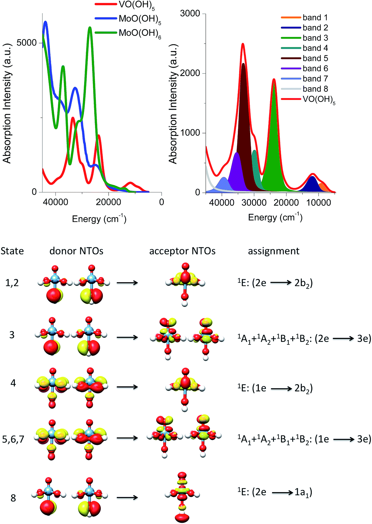 | ||
| Fig. 8 (Top left) B3LYP/TD-DFT un-shifted calculated spectra of the monomeric model structures V(V)O(OH)5 (red), Mo(VI)O(OH)5 (blue) and Mo(VI)O(OH)6 (green). (Top right) Deconvolution of the observed bands in terms of leading excited states that carry the largest oscillator strength. (Bottom) Band assignment on the basis of natural transition orbitals (NTOs), drawn with a 0.03 isosurface value. | ||
As it is seen in Fig. 8 (left), all calculated Mo(VI)O(OH)5 and Mo(VI)O(OH)6 bands are twice as intense as the corresponding V(V)O(OH)5 ones and, as discussed above, are found at higher energies. Quantitative analysis of these calculated bands is performed (1) by deconvoluting them in terms of the dominating leading excited states that carry the largest oscillator strengths and (2) by analyzing the nature of these states in terms of leading one electron excitations by evaluating the natural transition orbitals (NTOs) for these states.
This analysis is presented for the V(V)O(OH)5 model structure in Fig. 8 (bottom). The calculated absorption feature centered at 12000 cm−1 is dominated by 1E (2e → 2b2) states which involve O-2p electron excitations from the out of plane terminal M–O MOs into the essentially non-bonding dxy MO. As discussed above, the symmetry around the metal centers is lower than C4v, hence the state degeneracy is altered resulting in an asymmetric absorption feature. The absorption band located at 23000 is solely dominated by the 1A1 + 1A2 + 1B1 + 1B2 (2e → 2b2) states which involve O-2p electron excitations from the out of plane terminal M–O MOs into the π* MO MOs. All of these four states reside in a narrow energy range between 21000 and 26000 cm−1. Finally the higher energy absorption bands located at 30000 and 33000 cm−1 are dominated by a combination of states which involve O-2p excitations from the in and out of plane terminal M–O MOs: 1E (1e → 2b2), 1A1 + 1A2 + 1B1 + 1B2 (1e → 3e) and 1E (2e → 1a1). An analogous discussion holds for the assignment of the spectral features of the corresponding Mo(VI)O(OH)5 or Mo(VI)O(OH)6 complexes.
Absorption spectra of dimeric model structures
In this section, we will use the electronic structure arguments established above for the monomeric model structures in order to develop a theoretical protocol that will be used to analyze the experimental absorption and rR spectra of the M1 VMoOx catalyst. This protocol will be first validated on the dimeric model structures presented in Fig. 4.The B3LYP/TD-DFT calculated absorption spectra are presented in Fig. 9 (top left) for all five dimers. Qualitatively, all of the spectra differ substantially with each other. This indicates that the ratio of the different M–O–M building units is crucial for the correct prediction of the spectroscopic properties. Once again the energy region between 5000 and 15000 cm−1 is dominated by the absorption features of the vanadium based dimeric models VOV_ax and VOV_eq. Moreover, the absorption features of the VOV_ax, MoOMo_ax_a and MoOMo_ax_b models dominate the energy region between 15000 and 30000 cm−1, while at higher energies the absorption features of almost all structures can be found. As expected, the spectra of the dimeric models containing MoOx cores are all blue shifted with respect to the ones constructed solely from VOx cores, owning to the difference in d-orbital splitting. Interestingly, the spectrum of VOV_ax shows the simplest structure containing just three distinguishable bands observed at 12000, 24000 and 31000 cm−1. Furthermore, this spectrum is qualitatively similar to the experimental absorption spectrum presented in Fig. 3. Hence this model structure is considered as a good candidate to analyze the origin of the calculated spectral features and validate our theoretical protocol.
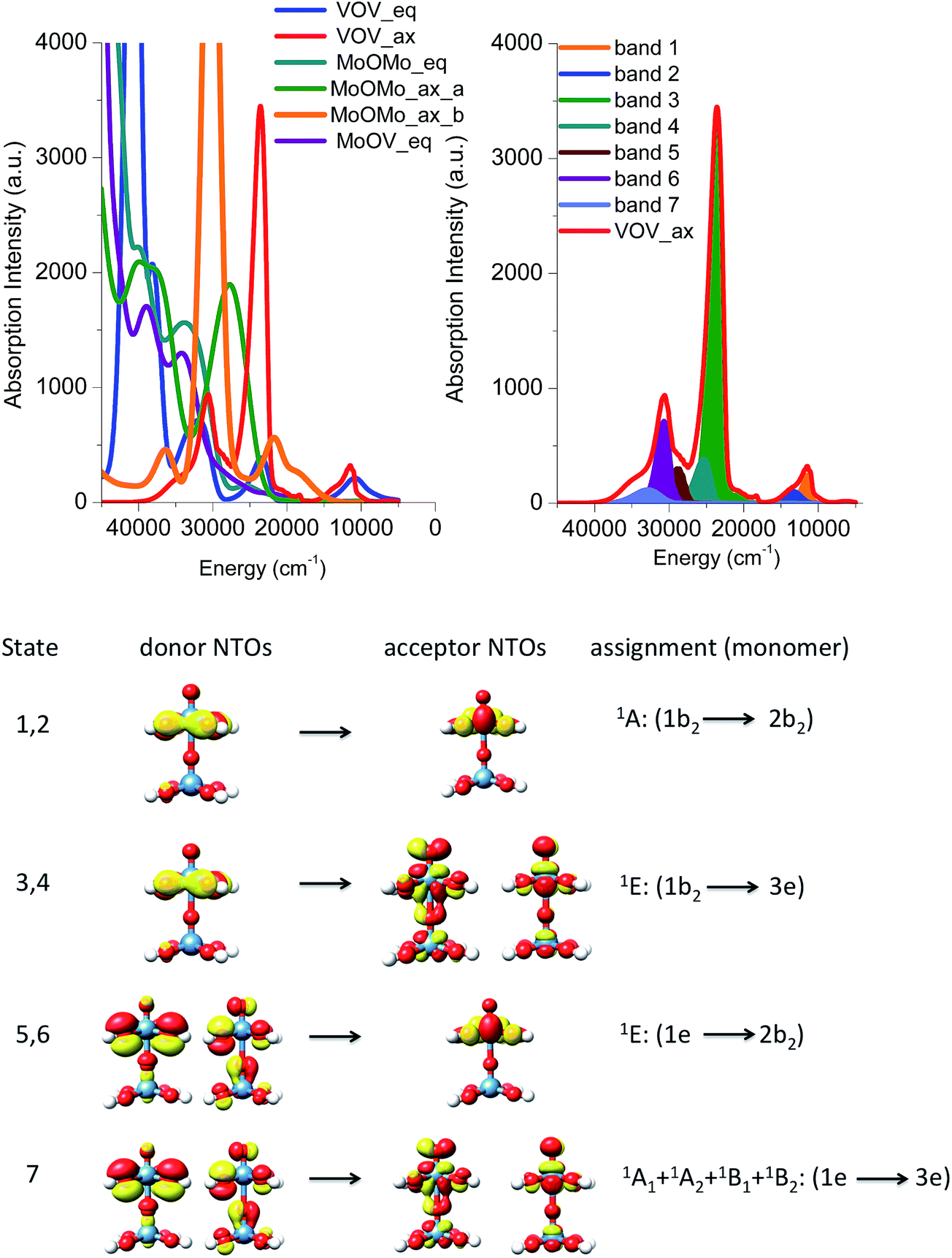 | ||
| Fig. 9 (Top left) B3LYP/TD-DFT un-shifted calculated spectra of the dimeric model structures VOV_ax (red), VOV_eq (blue), MoOMo_ax_a (green), MoOMo_ax_b (orange), MoOMo_eq (cyan) and MoOV_eq (purple). (Top right) Deconvolution of the observed bands in terms of leading excited states that carry the largest oscillator strength. (Bottom) Band assignment on the basis of natural transition orbitals (NTOs), drawn with a 0.03 isosurface value. | ||
As in the case of the monomeric model structures, the assignment of the bands is performed by identifying the excited states with the largest oscillator strengths and evaluating the natural transition orbitals for these states (Fig. 9, right and bottom). The advantage of this approach is that without the extra effort the local nature of the leading transitions for the dimeric structures can be described with the electronic structure protocol developed for the monomeric model structures. Hence the absorption feature at 12000 and 24000 cm−1 is dominated by 1E (1b2 → 2b2) and 1E (1b2 → 3e) states which involve O-2p electron excitations from the in plane terminal M–O MO into the essentially non-bonding dxy MO and the π* MO MOs, respectively. Moreover, the higher energy absorption bands located at 31000 are again dominated by a combination of states which involve O-2p excitations from the in and out of plane terminal M–O MOs: 1E (1e → 2b2) and 1A1 + 1A2 + 1B1 + 1B2 (1e → 3e), respectively. Furthermore, we compare the results of the NTO analysis performed on the monomeric and dimeric VO(OH)5 and VOV_ax model structures in Fig. 8 and 9. It can be concluded that in the two spectra the calculated bands are dominated by states with different donor and acceptor NTOs. This is expected owing to the slight differences in the electronic structure and to the different local coordination environments around the metal centers (e.g. monomer versus dimer). However, in both cases the bands located at ∼16000 and 25000 cm−1 belong to LMCT transitions that involve acceptor orbitals with significant non-bonding and antibonding character respectively.
Resonance Raman spectra
The respective rRaman spectra for this simplified model were calculated by setting the excitation frequency into pre-resonance with the absorption bands at 12000, 15000 and 20000 cm−1 as represented by the orange, blue and green arrows, respectively (Fig. 10). These excitation frequencies can be thought of as analogous to the experimental excitation frequencies of 18797 cm−1 (532 nm), 20491 cm−1 (488 nm), and 30770 cm−1 (325 nm), respectively, that are presented in Fig. 3.
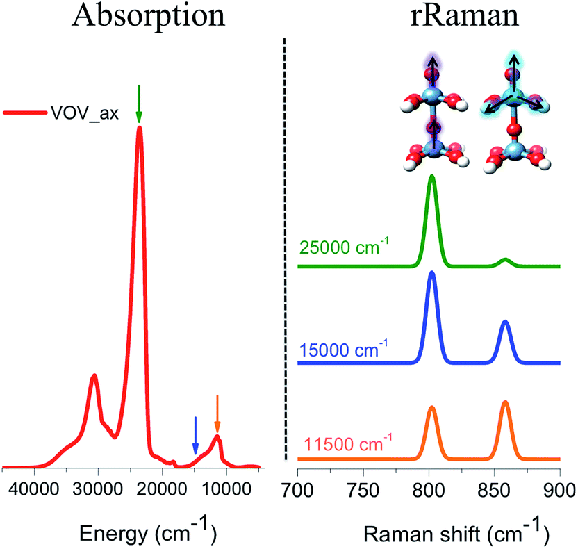 | ||
| Fig. 10 (Left) Calculated B3LYP/TD-DFT absorption spectrum of VOV_ax. (Right) Calculated B3LYP/TD-DFT rRaman spectra evaluated at frequencies around bands located at 11500, 15000 and 20000 cm−1 as indicated by the respective orange, blue and green arrows. | ||
The evaluated rRaman spectra (Fig. 10) consist of two main peaks located at 800 and 860 cm−1 which are assigned to the stretching vibrations of VO (vanadyl–oxo), as well as the ‘breathing’ stretching vibrations of the V–O bonds, as shown in Fig. 10. As long as the excitation frequency stays in resonance with the excitation energy of the band located at 12000 cm −1, both rRaman peaks are observed in ∼1:1 ratio. This is expected as this band is dominated by LMCT transitions involving essentially non-bonding or slightly anti-bonding in plane π* (V–O) MOs. However, as the excitation frequency is tuned towards the excitation energy of the bands located at 15000 and 20000 cm−1, the 1E (1b2 → 3e) state starts to dominate the spectral features. As a result, the out-of-plane π* vanadyl (VO) chromophore is excited and the rRaman peak corresponding to the vanadyl stretching vibration (800 cm−1) is progressively enhanced and eventually dominates the rRaman spectra.
The above presented theoretical protocol for evaluating the absorption and rRaman spectra will now be employed on more realistic cluster models in order to allow direct comparisons of the calculated versus experimental spectral features.
Calculations on cluster models
000, 30000, and 38000 cm−1 are successfully reproduced in terms of relative energies and intensities. It should be highlighted that this calculated spectrum is also similar to the one observed by employing the VOV_ax dimeric model structure. This is not surprising as in fact both model structures contain similar V–O–V building blocks. The cyclic cluster 3 containing an in plane V–O–V defect topology is also able to successfully reproduce the three major experimental features in terms of energy position and band separations. However, the intensity of the calculated spectral envelope around 30000 cm−1 is underestimated by a factor of 3 relative to the experiment. All of the other five clusters (1a, 2a, 2b, 4a and 4b) can at best reproduce a part of the experimental spectrum, within the applied excitation scheme, while none of the above five clusters are able to predict the low energy band observed at around 18000 cm−1. Once again this agrees very well with the observations from the simple monomeric and dimeric model structures. Apparently, this low energy absorption feature can only be reproduced by vanadium based building units.
 | ||
| Fig. 11 Experimental (black) versus calculated (red) TD-DFT/B3LYP absorption spectra for cluster models 1–4. 50–100 roots are considered in order to ensure saturation of the lowest lying spectroscopic features. A constant positive shift of 3000 cm−1 was applied to all spectra in order to achieve the best visual agreement with the experiment. | ||
In an effort to obtain insight into the electronic nature of the computed spectral features of the cluster models, we will employ the theoretical protocol developed above for the monomeric and dimeric models. Likewise insight into the nature of the calculated absorption bands can be obtained by analyzing the natural transition orbitals for the dominating LMCT transitions. In fact the calculated states dominating the absorption bands can be grouped according to the character of the predominant single electron excitation. By performing the above analysis to all six cluster models presented in Fig. 5, the contributing states can be grouped to a minimum of five absorption bands [1]–[5] in agreement with the Gaussian fit presented in Fig. 3. The intensity and energy distribution for each calculated spectrum is presented in Fig. 11, however, as the spectrum of cluster 1b provides the best qualitative agreement with the experiment, this spectrum is further used to assign these bands.
The band assignment for cluster 1b is provided in Fig. 12. Due to the local nature of the involved transitions once again the assignment scheme developed for the monomeric structures is employed. Similar to the cases of the monomeric and dimeric model structures, the low energy band [1] is dominated by 1A (1b2 → 2b2) states which involve O-2p electron excitations from the in plane terminal M–O MO into the essentially non-bonding dxy MO and mostly stem from the V–O–V motif. In addition, bands [2] and [3] are dominated by 1E (1b2 → 3e) states which involve O-2p excitations from the in- and out-of-plane terminal M–O MOs into the unoccupied antibonding vanadyl (VO) and molybdenyl (MoO) π*-MOs, respectively. Finally, band [4] is dominated by 1E (1e → 2b2) states which involve single electron excitations from the out of plane terminal M–O MOs into the non-bonding dxy MO that comprises the equatorial V–O–Mo units. Furthermore, the high energy band [5] (observed e.g. in the case of cluster 3) contains a group of states that involves excitations into the dx2−y2 and dz2 MOs.
 | ||
| Fig. 12 Natural transition orbitals (0.03 isosurface value) of the dominant LMCT (O-2p → V-3d/Mo-4d) transitions for bands [1–4] and cluster 1b. | ||
The above analysis indicates that only clusters 1b, 2b and 3, which contain topologies composed of in-plane and out-of-plane V–O–V building units, are able to reproduce the low energy feature around 18000 cm−1 (band [1]). Moreover, as observed by inspecting Fig. 5 for the defect structure of cluster 2b, the presence of both the out-of-plane OMo⋯OMo and OV⋯OV units results in an energy shift towards higher energies of the calculated low energy band. On the basis of the analysis on the monomeric and dimeric models described above, such a phenomenon is associated to the weaker ligand field strength of the coordination environments involving Mo centers. Hence structures containing solely this motif will fail to reproduce the corresponding experimental absorption band.
000 cm−1 (band [1]) feature reproduced the main experimentally observed signals located at 850 and 950 cm−1. In particular, the signal centered at 850 cm−1 originates from a combination of vibrations involving VO stretching, MoO stretching and symmetric in plane V–O–Mo ‘breathing’ vibrational modes (A and C), which all happen to fall into the same spectral region. In fact, the isolated VO, MoO and V–O–Mo vibrational modes are observed at 853, 845 and 841 cm−1, respectively. The coupling of the same modes also accounts for the low intensity pattern between 600 and 800 cm−1, where contributions from the Mo–O–Mo stretching vibration are also observed (A–C). The signal located at 950 cm−1 mainly originates from the symmetric out-of-plane interlayer V–O–V stretching vibrations (D). It should be highlighted that, as in the case of the VOV_ax model, the above analysis shows that none of the calculated signals is resonantly enhanced due to the fact that band [1] involves electron excitations into the essentially non-bonding dxy MO.
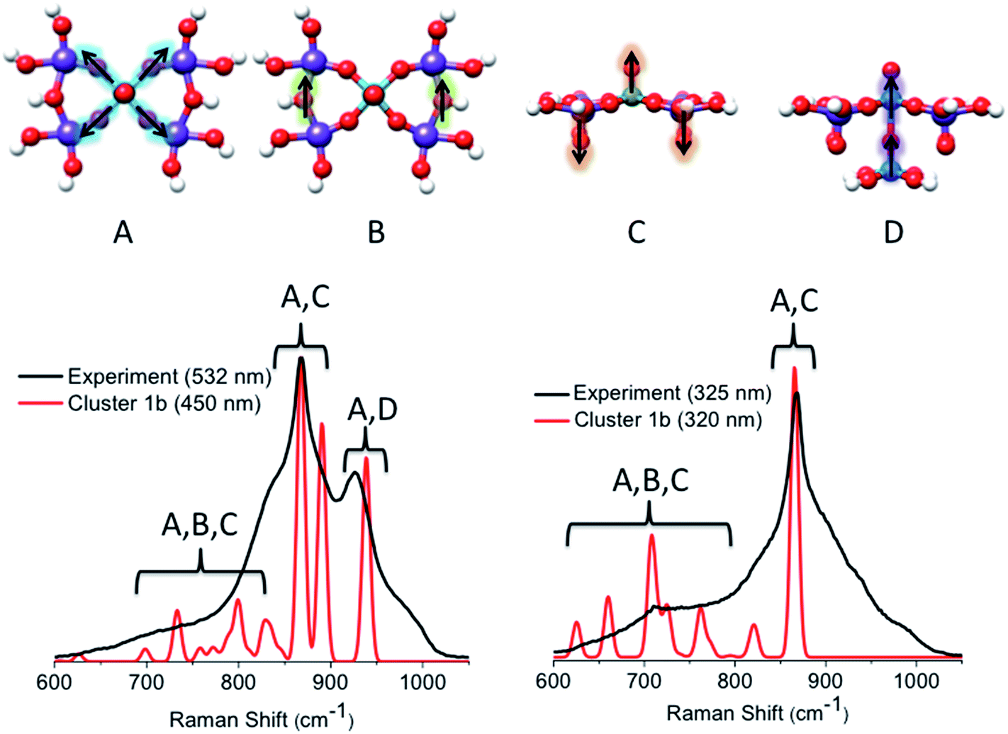 | ||
| Fig. 13 (Top) The dominant vibrational modes of cluster 1b observed in the rR spectra. They refer to in plane V–O–V (A), in plane Mo–O–Mo (B), VO and MoO (C) and out of plane V–O–V (D) stretching vibrations. Experimental (black) versus calculated (red) TD-DFT/B3LYP rR spectra are evaluated at the excitation energies around bands [1]–[3]. | ||
On the other hand, by tuning the excitation frequency near bands [2] or [3], rather strong enhancements are expected for the signal located at 850 cm−1 as this signal is dominated by VO and MoO stretching vibrations. Moreover, the calculated features corresponding to the out of plane V–O–V stretching vibrations vanish. Clearly, the enhancement of VO and MoO stretching vibrations is consistent with the assignment of the absorption spectra, which implicate the VO and MoO antibonding orbitals as acceptors in the LMCT process. We notice, however, that the broad pattern around the main signal located at 950 cm−1 is not reproduced by the rR calculations, thus indicating that cluster 1b is still somewhat too simplistic.
Similar arguments can be made by analyzing the calculated rR spectra using excitation energies near the calculated bands [1]–[3] for cluster 3 (Fig. 14). Once again, both spectra are dominated by a combination of symmetric vibrations involving the in plane V–O–Mo (A), V–O–V (B), and VO and MoO (C) functional groups. In particular, the in plane V–O–V stretching vibrations dominate the 950 cm−1 signal originating from the 18000 cm−1 absorption feature (band [1]). However, this signal is calculated at a much lower intensity than the corresponding calculated signal of cluster 1b. Furthermore, at excitation frequencies around bands [2] and [3], the rR features are characterized by contributions arising from the in plane V–O–V (B) and VO and MoO (C) vibrational modes. Once again, by tuning the excitation frequency around bands [2] or [3], resonantly enhanced Raman bands are observed. These bands are dominated by VO and MoO stretching vibrations located at 850, 860 and 890 cm−1. On the other hand, the Raman peak dominated by the in plane V–O–V stretching vibrations (950 cm−1) vanishes. We further investigated clusters 1a, 2a, 2b, 4a and 4b. The results are summarized in Fig. S2.† The rRaman spectra that are generated at absorption features located at energies >20000 cm−1 contain Raman features in the 600–900 cm−1 region. As in the cases of clusters 1b and 3, in cluster 1a the rRaman spectrum associated with the 17000 cm−1 absorption feature contains the additional characteristic 950 cm−1 Raman feature. It should be noted that this absorption feature has very low intensity due to the absence of V–O–V building units. As discussed above the observed 950 cm−1 Raman feature is dominated by the ‘breathing’ stretching VO vibration and loses intensity upon using higher excitation energies. Once again this is due to intensity enhancements in the 800–900 cm−1 Raman shift region dominated by the mixed MoO and VO stretching vibrational modes.
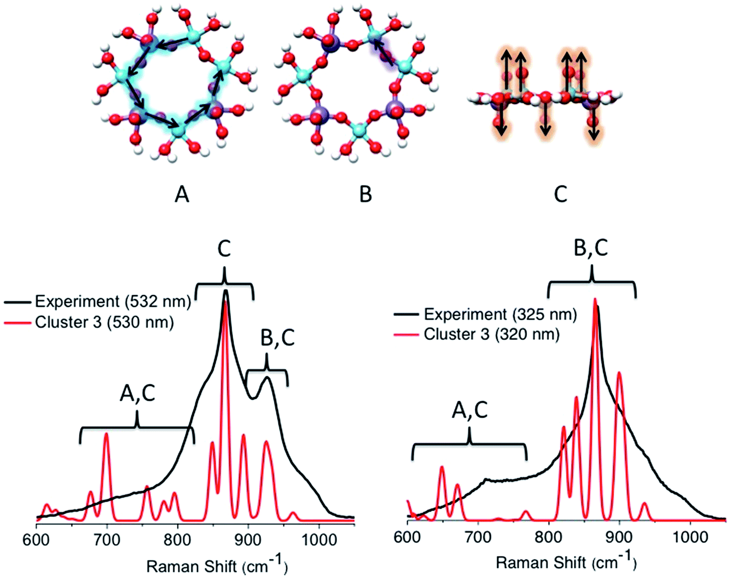 | ||
| Fig. 14 (Top) The dominant vibrational modes of cluster 3 observed in the rR spectra. They refer to in plane V–O–Mo (A), in plane V–O–V (B) and VO and MoO (C) stretching vibrations. Experimental (black) versus calculated (red) TD-DFT/B3LYP rR spectra are evaluated at the excitation energies around bands [1]–[3]. | ||
Contribution of different cluster topologies to the observed spectral features
Up until now we have been able to identify the two important topologies described by cluster 1b and 3 that are able to successfully reproduce the major experimentally observed spectral features for both the absorption and rR spectra of the M1 MoVOx catalyst. In an effort to arrive at a more quantitative description of the experimental spectra, we further investigate the variation of the calculated spectroscopic features with variations in the cluster topology. Given that in the real system, there probably exists a mixture of different structural motifs, we performed a weighted fit of the calculated spectra to the experimental ones. As has been recently described,27 similar protocols can provide a reasonable quantitative analysis on complicated solid-state spectroscopic problems. In this work we perform a simpler version in which the absorption spectra of cluster 1b and 3 are mixed through the relation:| α × cluster 1b + (1 − α) × cluster 3 | (1) |
:2 ratio (Fig. 1, right) as effective molecular topologies of the M1 MoVOx crystallographic structure that dominate the spectroscopic response of the catalyst.
 | ||
| Fig. 15 (Top) B3LYP/TD-DFT calculated absorption spectra for admixtures of cluster 1b and cluster 3 according to the relation (1) for α values ranging between 1 and 0. The red spectra at α = 0.7 indicate the best agreement between theory and the experiment. A constant positive shift of 3000 cm−1 was applied in all of the spectra in order to achieve the best visual agreement with experiment. (Bottom) Experimental (black) versus calculated (red) rR spectra assuming 67% and 33% admixtures of cluster 1b and cluster 3, respectively. | ||
Conclusions
In this work we presented a systematic experimental and theoretical study on the structure of M1 MoVOx catalysts. Absorption as well as multiwavelength resonance Raman spectroscopy revealed frequency dependencies that are directly related to the topological motifs of the semi-crystalline catalyst. In order to interpret the experimental findings, we constructed a representative library of mono-, di- and multi-metallic cluster models extracted directly from the crystallographic super-shell and employed a general theoretical protocol that involves large cluster sizes (up to 9 metal centers) together with charge neutralization techniques (H-saturation). Special care was taken to include all of the important interactions between the metal and oxygen atoms. In fact, the choice of the structural motifs was based on a detailed bonding analysis. In particular, the choice of the 3D structural models was justified on the basis of the DLPNO-CCSD(T) PESs along normal modes connecting monolayer motifs. For the chosen clusters, the absorption and the rR spectra were calculated. The calculated spectra were analyzed in terms of topology variation convergence and dominant local molecular interactions. According to our assignment, the unique low energy absorption feature around 18000 cm−1 is dominated by LMCT excitations that involve topologies containing in-plane and out-of-plane V–O–V units, which also account for the prominently enhanced rR feature around 950 cm−1. Moreover, quantitative band-fitting analysis implies that the monolayer Mo3V4O28 as well as the bilayer Mo4V2O24 motifs contribute to the observed spectral features in a roughly 1:2 ratio. In order to further support these conclusions, ongoing experimental and computational studies of the X-ray spectroscopic properties of the catalyst are underway in our laboratories. Ultimately, we hope to arrive at structure/reactivity correlations through the combined analysis of in situ spectroscopy, reactivity studies and detailed electronic structure calculations involving cluster size convergence. The present work represents the first step in this direction, showing that due to the local nature of the absorption phenomena, it is possible to directly apply molecular based theoretical protocols to describe the spectroscopic response of solid materials.
Acknowledgements
The authors gratefully acknowledge the financial support for this work from the Max Planck Society. This work was conducted in the framework of the BasCat collaboration between BASF SE, TU Berlin, FHI, and the cluster of excellence “Unified Concepts in Catalysis” (UniCat http://www.unicat.tu-berlin.de). The authors thank Stephen Lohr for the preparation of MoVOx. The reviewers of the manuscript are acknowledged for their constructive comments.References
- R. Schlögl, Top. Catal., 2011, 54, 627 CrossRef.
- F. Cavani, N. Ballarini and A. Cericola, Catal. Today, 2007, 127, 113–131 CrossRef CAS.
- R. Grasselli, D. Buttrey, J. Burrington, A. Andersson, J. Holmberg, W. Ueda, J. Kubo, C. Lugmair and A. Volpe Jr, Top. Catal., 2006, 38, 7–16 CrossRef CAS.
- F. Cavani and J. H. Teles, ChemSusChem, 2009, 2, 508–534 CrossRef CAS PubMed.
- K. Amakawa, Y. V. Kolen’ko, A. Villa, M. E. Schuster, L.-I. Csepei, G. Weinberg, S. Wrabetz, R. Naumann d’Alnoncourt, F. Girgsdies, L. Prati, R. Schlögl and A. Trunschke, ACS Catal., 2013, 3, 1103–1113 CrossRef CAS.
- A. C. Sanfiz, T. W. Hansen, D. Teschner, P. Schnörch, F. Girgsdies, A. Trunschke, R. Schlögl, M. H. Looi and S. B. A. Hamid, J. Phys. Chem. C, 2010, 114, 1912–1921 CAS.
- W. D. Pyrz, D. A. Blom, N. R. Shiju, V. V. Guliants, T. Vogt and D. J. Buttrey, J. Phys. Chem. C, 2008, 112, 10043–10049 CAS.
- Q. He, J. Woo, A. Belianinov, V. V. Guliants and A. Y. Borisevich, ACS Nano, 2015, 9, 3470–3478 CrossRef CAS PubMed.
- E. M. Thorsteinson, T. P. Wilson, F. G. Young and P. H. Kasai, J. Catal., 1978, 52, 116–132 CrossRef CAS.
- D. Vitry, Y. Morikawa, J. L. Dubois and W. Ueda, Top. Catal., 2003, 23, 47–53 CrossRef CAS.
- J. B. Wagner, D. S. Su, S. A. Schunk, H. Hibst, J. Petzoldt and R. Schlögl, J. Catal., 2004, 224, 28–35 CrossRef CAS.
- R. Grasselli, Catal. Today, 2005, 99, 23 CrossRef CAS.
- V. V. Guliants, R. Bhandari, B. Swaminathan, V. K. Vasudevan, H. H. Brongersma, A. Knoester, A. M. Gaffney and S. J. Han, J. Phys. Chem. B, 2005, 109, 24046 CrossRef CAS PubMed.
- A. Celaya Sanfiz, T. W. Hansen, D. Teschner, P. Schnörch, F. Girgsdies, A. Trunschke, R. Schlögl, M. H. Looi and S. B. A. Hamid, J. Phys. Chem. C, 2010, 114, 1912 Search PubMed.
- M. Hävecker, S. Wrabetz, J. Kröhnert, L. I. Csepei, R. Naumann d’Alnoncourt, Y. V. Kolen’ko, F. Girgsdies, R. Schlögl and A. Trunschke, J. Catal., 2012, 285, 48 CrossRef.
- V. V. Guliants, R. Bhandari, A. R. Hughett, S. Bhatt, B. D. Schuler, H. H. Brongersma, A. Knoester, A. M. Gaffney and S. J. Han, J. Phys. Chem. B, 2006, 110, 6129 CrossRef CAS PubMed.
- F. N. Naraschewski, A. Jentys and J. A. Lercher, Top. Catal., 2011, 54, 639 CrossRef CAS.
- L. Luo, J. A. Labinger and M. E. Davis, J. Catal., 2001, 200, 222 CrossRef CAS.
- E. Balcells, F. Borgmeier, I. Grißtede and H. G. Lintz, Catal. Lett., 2003, 87, 195 CrossRef CAS.
- R. Naumann d’Alnoncourt, Y. V. Kolen’ko, R. Schlögl and A. Trunschke, Comb. Chem. High Throughput Screening, 2012, 15, 161 CrossRef.
- Y. V. Kolen’ko, W. Zhang, R. N. d’ Alnoncourt, F. Girgsdies, T. W. Hansen, T. Wolfram, R. Schlögl and A. Trunschke, ChemCatChem, 2011, 3, 1597 CrossRef.
- G. Fu, X. Xu and P. Sautet, Angew. Chem., 2012, 124, 13026–13030 CrossRef.
- M.-J. Cheng and W. A. Goddard, Top. Catal., 2016, 59, 1506–1517 CrossRef CAS.
- M. Cavalleri, K. Hermann, A. Knop-Gericke, M. Haevecker, R. Herbert, C. Hess, A. Oestereich, J. Doebler and R. Schlögl, J. Catal., 2009, 262, 215–223 CrossRef CAS.
- C. Moisii, M. D. Curran, L. J. van de Burgt and A. E. Stiegman, J. Mater. Chem., 2005, 15, 3519–3524 RSC.
- C. Moisii, L. J. van de Burgt and A. E. Stiegman, Chem. Mater., 2008, 20, 3927–3935 CrossRef CAS.
- D. Maganas, A. Trunschke, R. Schlogl and F. Neese, Faraday Discuss., 2016, 188, 181–197 RSC.
- J. C. Schöneboom, F. Neese and W. Thiel, J. Am. Chem. Soc., 2005, 127, 5840–5853 CrossRef PubMed.
- S. Ye, C.-Y. Geng, S. Shaik and F. Neese, Phys. Chem. Chem. Phys., 2013, 15, 8017–8030 RSC.
- S. Ye and F. Neese, Proc. Natl. Acad. Sci. U. S. A., 2011, 108, 1228–1233 CrossRef CAS PubMed.
- K. M. Lancaster, M. Roemelt, P. Ettenhuber, Y. Hu, M. W. Ribbe, F. Neese, U. Bergmann and S. DeBeer, Science, 2011, 334, 974–977 CrossRef CAS PubMed.
- D. A. Pantazis, W. Ames, N. Cox, W. Lubitz and F. Neese, Angew. Chem., Int. Ed., 2012, 51, 9935–9940 CrossRef CAS PubMed.
- N. Cox, M. Retegan, F. Neese, D. A. Pantazis, A. Boussac and W. Lubitz, Science, 2014, 345, 804–808 CrossRef CAS PubMed.
- C. Riplinger and F. Neese, J. Chem. Phys., 2013, 138, 034106 CrossRef PubMed.
- D. G. Liakos, M. Sparta, M. K. Kesharwani, J. M. L. Martin and F. Neese, J. Chem. Theory Comput., 2015, 11, 1525–1539 CrossRef CAS PubMed.
- D. G. Liakos and F. Neese, J. Chem. Theory Comput., 2015, 11, 4054–4063 CrossRef CAS PubMed.
- Y. Minenkov, E. Chermak and L. Cavallo, J. Chem. Theory Comput., 2015, 11, 4664–4676 CrossRef CAS PubMed.
- A. Kubas, D. Berger, H. Oberhofer, D. Maganas, K. Reuter and F. Neese, J. Phys. Chem. Lett., 2016, 7, 4207–4212 CrossRef CAS PubMed.
- A. Trunschke, J. Noack, S. Trojanov, F. Girgsdies, T. Lunkenbein, V. Pfeifer, M. Havecker, P. Kube, C. Sprung, F. Rosowski and R. Schlögl, ACS Catal., 2017, 7, 3061–3071 CrossRef CAS.
- F. Neese, Wiley Interdiscip. Rev.: Comput. Mol. Sci., 2012, 2, 73–78 CrossRef CAS.
- S. Grimme, J. Antony, S. Ehrlich and H. Krieg, J. Chem. Phys., 2010, 132, 154104 CrossRef PubMed.
- S. Grimme, S. Ehrlich and L. Goerigk, J. Comput. Chem., 2011, 32, 1456–1465 CrossRef CAS PubMed.
- K. Eichkorn, O. Treutler, H. Öhm, M. Häser and R. Ahlrichs, Chem. Phys. Lett., 1995, 240, 283–290 CrossRef CAS.
- F. Neese, F. Wennmohs, A. Hansen and U. Becker, Chem. Phys., 2009, 356, 98–109 CrossRef CAS.
- B. A. Hess, Phys. Rev. A: At., Mol., Opt. Phys., 1985, 32, 756 CrossRef CAS.
- B. A. Hess, Phys. Rev. A: At., Mol., Opt. Phys., 1986, 333, 3742 CrossRef.
- G. Jansen and B. A. Hess, Phys. Rev. A: At., Mol., Opt. Phys., 1989, 39, 6016 CrossRef.
- A. Schäfer, C. Huber and R. Ahlrichs, J. Chem. Phys., 1994, 100, 5829–5835 CrossRef.
- F. Weigend and R. Ahlrichs, Phys. Chem. Chem. Phys., 2005, 7, 3297–3305 RSC.
- F. Weigend, Phys. Chem. Chem. Phys., 2006, 8, 1057–1065 RSC.
- A. Halkier, W. Klopper, T. Helgaker, P. Jo/rgensen and P. R. Taylor, J. Chem. Phys., 1999, 111, 9157–9167 CrossRef CAS.
- F. Neese and E. F. Valeev, J. Chem. Theory Comput., 2011, 7, 33–43 CrossRef CAS PubMed.
- E. Runge and E. K. U. Gross, Phys. Rev. Lett., 1984, 52, 997–1000 CrossRef CAS.
- I. Tamm, J. Phys., 1945, 9, 449 Search PubMed.
- S. M. Dancoff, Phys. Rev., 1939, 55, 959 CrossRef CAS.
- F. Neese, T. Petrenko, D. Ganyushin and G. Olbrich, Coord. Chem. Rev., 2007, 251, 288–327 CrossRef CAS.
- T. Petrenko, S. Kossmann and F. Neese, J. Chem. Phys., 2011, 134, 054116 CrossRef PubMed.
- T. Petrenko and F. Neese, J. Chem. Phys., 2007, 127, 164319 CrossRef PubMed.
- T. Petrenko and F. Neese, J. Chem. Phys., 2012, 137, 234107 CrossRef PubMed.
- I. J. Bruno, J. C. Cole, P. R. Edgington, M. Kessler, C. F. Macrae, P. McCabe, J. Pearson and R. Taylor, Acta Crystallogr., Sect. B: Struct. Sci., 2002, 58, 389–397 CrossRef.
- K. Amakawa, L. Sun, C. Guo, M. Haevecker, P. Kube, I. E. Wachs, S. Lwin, A. I. Frenkel, A. Patlolla, K. Hermann, R. Schlögl and A. Trunschke, Angew. Chem., Int. Ed., 2013, 52, 13553–13557 CrossRef CAS PubMed.
- P. Gruene, T. Wolfram, K. Pelzer, R. Schlögl and A. Trunschke, Catal. Today, 2010, 157, 137–142 CrossRef CAS.
- N. Hamilton, T. Wolfram, G. T. Mueller, M. Haevecker, J. Kroehnert, C. Carrero, R. Schomaecker, A. Trunschke and R. Schlögl, Catal. Sci. Technol., 2012, 2, 1346–1359 CAS.
- D. Maganas, S. DeBeer and F. Neese, Inorg. Chem., 2014, 53, 6374–6385 CrossRef CAS PubMed.
- D. Maganas, M. Roemelt, M. Havecker, A. Trunschke, A. Knop-Gericke, R. Schlögl and F. Neese, Phys. Chem. Chem. Phys., 2013, 15, 7260–7276 RSC.
- V. Staemmler, The Cluster Approach for the Adsorption of Small Molecules on Oxide Surfaces, in Theoretical Aspects of Transition Metal Catalysis, ed. G. Frenking, Springer, Berlin, Heidelberg, 2005, vol. 12, pp. 219–256 Search PubMed.
- G. Fronzoni, R. D. Francesco and M. Stener, J. Chem. Phys., 2012, 137, 224308 CrossRef PubMed.
- R. De Francesco, M. Stener and G. Fronzoni, Surf. Sci., 2011, 605, 500–506 CrossRef CAS.
- R. De Francesco, M. Stener, M. Causa, D. Toffoli and G. Fronzoni, Phys. Chem. Chem. Phys., 2006, 8, 4300–4310 RSC.
- M. Roemelt, D. Maganas, S. DeBeer and F. Neese, J. Chem. Phys., 2013, 138, 204101 CrossRef PubMed.
- D. Maganas, M. Roemelt, M. Havecker, A. Trunschke, A. Knop-Gericke, R. Schlögl and F. Neese, Phys. Chem. Chem. Phys., 2013, 15, 7260–7276 RSC.
- M. Hävecker, M. Cavalleri, R. Herbert, R. Follath, A. Knop-Gericke, C. Hess, K. Hermann and R. Schlögl, Phys. Status Solidi B, 2009, 246, 1459–1469 CrossRef.
- N. R. Shiju, A. J. Rondinone, D. R. Mullins, V. Schwartz, S. H. Overbury and V. V. Guliants, Chem. Mater., 2008, 20, 6611–6616 CrossRef CAS.
- M. Hävecker, S. Wrabetz, J. Kröhnert, L.-I. Csepei, R. Naumann d’Alnoncourt, Y. V. Kolen’ko, F. Girgsdies, R. Schlögl and A. Trunschke, J. Catal., 2012, 285, 48–60 CrossRef.
- Y. Zhu, W. Lu, H. Li and H. Wan, J. Catal., 2007, 246, 382–389 CrossRef CAS.
- C. Heine, M. Havecker, A. Trunschke, R. Schlögl and M. Eichelbaum, Phys. Chem. Chem. Phys., 2015, 17, 8983–8993 RSC.
Footnote |
| † Electronic supplementary information (ESI) available. See DOI: 10.1039/c7sc01771e |
| This journal is © The Royal Society of Chemistry 2017 |