DOI:
10.1039/C7SC00840F
(Edge Article)
Chem. Sci., 2017,
8, 5434-5439
Electrocatalytic synthesis of ammonia by surface proton hopping†
Received
22nd February 2017
, Accepted 20th May 2017
First published on 5th June 2017
Abstract
Highly efficient ammonia synthesis at a low temperature is desirable for future energy and material sources. We accomplished efficient electrocatalytic low-temperature ammonia synthesis with the highest yield ever reported. The maximum ammonia synthesis rate was 30![[thin space (1/6-em)]](https://www.rsc.org/images/entities/char_2009.gif) 099 μmol gcat−1 h−1 over a 9.9 wt% Cs/5.0 wt% Ru/SrZrO3 catalyst, which is a very high rate. Proton hopping on the surface of the heterogeneous catalyst played an important role in the reaction, revealed by in situ IR measurements. Hopping protons activate N2 even at low temperatures, and they moderate the harsh reaction condition requirements. Application of an electric field to the catalyst resulted in a drastic decrease in the apparent activation energy from 121 kJ mol−1 to 37 kJ mol−1. N2 dissociative adsorption is markedly promoted by the application of the electric field, as evidenced by DFT calculations. The process described herein opens the door for small-scale, on-demand ammonia synthesis.
099 μmol gcat−1 h−1 over a 9.9 wt% Cs/5.0 wt% Ru/SrZrO3 catalyst, which is a very high rate. Proton hopping on the surface of the heterogeneous catalyst played an important role in the reaction, revealed by in situ IR measurements. Hopping protons activate N2 even at low temperatures, and they moderate the harsh reaction condition requirements. Application of an electric field to the catalyst resulted in a drastic decrease in the apparent activation energy from 121 kJ mol−1 to 37 kJ mol−1. N2 dissociative adsorption is markedly promoted by the application of the electric field, as evidenced by DFT calculations. The process described herein opens the door for small-scale, on-demand ammonia synthesis.
Introduction
Ammonia is an important compound that is widely used as a raw material for chemical fertilizers, fibers, resins and refrigerants. Recently, ammonia has been suggested as a hydrogen carrier because of its high hydrogen content.1 At present, the Haber–Bosch process using nitrogen and hydrogen is the main method for ammonia synthesis. This process is conducted at high pressures (over 200 atm) and high reaction temperatures (around 773 K) because of its thermodynamic and kinetic limitations.2 For this reason, the energy consumption for ammonia synthesis is very large.3 Smaller scale, more dispersed ammonia plants could be developed if an ammonia synthesis route with milder operating conditions is realized. To date, numerous investigations into high-efficiency ammonia synthesis using milder operating conditions have been conducted. The original ammonia synthesis catalyst was an Fe-based double promotion catalyst.4 In 1972, Aika et al. reported a supported Ru catalyst5 that showed high activity for ammonia synthesis. This discovery of a Ru catalyst with alkali metals as co-catalysts6–11 led to a decrease in the reaction temperatures and pressures necessary for Haber–Bosch processing. Recently, Ru catalysts supported on praseodymium oxide,12 electride catalysts,13–15 and calcium amide16 have shown high ammonia synthesis rates, even at pressures and temperatures as low as 0.1 MPa and 600–700 K. In addition, ammonia synthesis at room temperature (around 298 K) and atmospheric pressure can be achieved using metal complexes including molybdenum,17,18 iron19 and cobalt,20 as well as with a titanium hydride compound.21 Moreover, examples of ammonia synthesis routes using an external DC electric field,22 plasma,23–28 photocatalysis29 and electrolysis30 have been reported, which indicate the possibility of low-temperature ammonia synthesis by exploiting the synergy between electrical/photochemical processes and catalysis. However, the ammonia synthesis rates using these methods are hindered by kinetic limitations. The present work proposes a new catalytic ammonia synthesis process assisted by an electric field which can show a high ammonia synthesis rate even at low temperatures. We achieved ammonia synthesis under very mild conditions (room temperature and pressures ranging from atmospheric up to 0.9 MPa) using a Ru–Cs catalyst. The process is more efficient than electrolytic synthesis because the process is non-faradaic (λ > 50). The process is also different from that using plasma, as it is conducted under much milder conditions with lower electric power consumption. This process is not intended as a replacement for the Haber–Bosch process, but rather for the creation of new uses and demand. Using this method of ammonia synthesis, highly pure ammonia can be collected as a compressed liquid by virtue of the extremely low reaction temperature. Therefore, small-scale and efficient processes for ammonia synthesis can be realized by application of an electric field.
Results and discussion
Kinetic analyses for catalytic ammonia synthesis in an electric field
We conducted pre-screening tests for this purpose (results not shown), and we found that 9.9 wt% Cs/5.0 wt% Ru/SrZrO3 showed high activity for ammonia synthesis in an electric field, even at low reaction temperatures in the range of 463–634 K and pressures from atmospheric to 0.9 MPa, as presented in Fig. 1(A). We obtained a remarkably high ammonia yield, with an ammonia production rate as high as 30099 μmol gcat−1 h−1 at 0.9 MPa, which is still in the kinetically controlled region. Interestingly, this impressive activity was also stable for 5 h. The application of an electric field increased the activity drastically, irrespective of the state of pressurization. The energy consumption was very low (only 2.82 W), and the ammonia production energy efficiency of 36.3 g kW h−1 is the highest ever reported. The faradaic efficiency (i.e. the ratio between the molar amounts of NH3 produced and electrons consumed) was as high as 26.88, strongly indicating that the reaction is non-faradaic. Interestingly, the pressure effects were more pronounced when the reaction proceeded under the influence of an electric field.
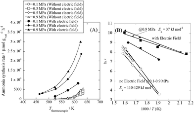 |
| | Fig. 1 Temperature and pressure dependence of ammonia synthesis activity with or without an electric field. (A) Temperature dependence of the ammonia synthesis rate at various pressures, with or without an electric field. (B) Arrhenius plots for each reaction under various pressures in the kinetic regime: catalyst bed temperature, 463–634 K; catalyst, 9.9 wt% Cs/5.0 wt% Ru/SrZrO3, 200 mg; flow, N2:H2 = 60:180 SCCM; current, 0 or 6 mA. | |
To elucidate the mechanism behind the electric field effect on catalytic ammonia synthesis, we conducted detailed kinetic analyses of the reaction. Fig. 1(B) presents Arrhenius plots for the ammonia synthesis reaction in the kinetic regime under both atmospheric and elevated pressure. The apparent activation energy decreased from 121 kJ mol−1 to 37 kJ mol−1 upon applying the electric field at 0.9 MPa. These results suggest that the ammonia synthesis reaction mechanism is affected by the electric field, and that the rate-determining step of the reaction changes.
To gain further mechanistic information, the N2, H2 and NH3 pressure dependencies of the ammonia synthesis rate were investigated. The obtained results are presented in Table S1 of the ESI.† With the assumption that the rate of the ammonia synthesis reaction can be written as in eqn (1), eqn (2)–(5) were used for kinetic analyses:31,32
| | | logy0 = log(c/q)1/m | (3) |
where
r stands for the reaction rate of the ammonia synthesis,
W denotes the catalyst weight,
y0 signifies the ammonia mole fraction,
q represents the mass flow and (1 −
m) corresponds to
γ.
As shown in Table S1,† for the catalytic reaction (without the electric field), the ammonia synthesis rate exhibited a positive N2 partial pressure dependence with an order of 0.68. However, the H2 and NH3 partial pressure dependencies of the reaction rate were negative (−0.21 for H2 and −0.1 for NH3). These trends are in excellent agreement with past kinetic studies of ammonia synthesis.8,11,32,33 They indicated that the rate-determining steps of the catalytic reaction without the electric field include N2 activation, especially N2 dissociative adsorption on Ru, because of the strong triple bond energy of N2. However, when the catalyst included an electron donor such as Cs, the reaction order of N2 became smaller than unity, at around 0.7.8 In addition, the negative H2 pressure dependence indicates that the surface of Ru was poisoned by hydrogen. On the other hand, upon application of the electric field, the N2 and H2 pressure dependencies of the ammonia synthesis rate changed drastically. The N2 pressure dependence of the reaction rate decreased upon applying the electric field, indicating that the N2 activation steps were promoted by the electric field. In addition, the H2 pressure dependence of the reaction rate weakened; the reaction orders were 0.24 for N2, 0 for H2 and −0.26 for NH3. Therefore, the poisoning of Ru by hydrogen disappeared to some extent upon application of the electric field.
To specifically examine the effect of the electric field on N2 activation, isotope exchange tests were conducted using 30N2. Fig. 2 presents the results obtained in transient response tests using 28N2 and switching to 30N2. When 30N2 was supplied in the presence of the electric field at 473 K, 29N2 formation was observed. However, without the electric field, 29N2 was not detected, even at higher reaction temperatures, as shown in Fig. 2 (T ≤ 673 K). Generally, the isotope exchange tests using 30N2 were conducted while only supplying N2 species to avoid H2 poisoning of the Ru surface.34 In our isotopic tests without supplying H2 and without application of the electric field, 29N2 was not detected either, even at 873 K (Fig. S1†). In addition, H2 was necessary for the isotopic tests when applying the electric field because without a hydrogen supply, application of the electric field resulted in a spark discharge. This phenomenon demonstrates that hydrogen, or a chemical compound containing hydrogen, plays the role of an ion carrier, enabling the stable application of the electric field.
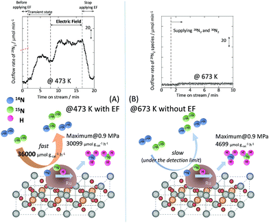 |
| | Fig. 2 Isotope exchange tests using 30N2, (A) with an electric field at 473 K, and (B) without an electric field at 673 K. Catalyst, 9.9 wt% Cs/5.0 wt% Ru/SrZrO3, 200 mg; flow, 28N2:30N2:H2:Ar = 6:6:36:12 SCCM; current, 0 or 6 mA. | |
As shown in eqn (6), 29N2 was produced through the dissociative adsorption of 28N2 and 30N2, followed by the recombination of 28N2 and 30N2. The N2 dissociation rate can therefore be calculated from the 29N2 production rate, using eqn (7)–(9), assuming steady-state conditions at the surface of the catalyst:34,35
The balance equation for N species flow is
| | | Vin − Vout − rNH3/2 = 0 | (7) |
and the equations for N
2 outflow are
| | | F28 = (F28)0 + Vout × (fs14fs14) − Vin × (f28)0 | (8) |
and
| | | F29 = Vout × (2fs14fs15) = Vout × {2fs14 × (1 − fs14)}, | (9) |
where
V signifies the total flow rate,
F denotes the flow of each species, and
f represents the mole fraction of the isotopic species. Subscripts 28, 29, 14 and 15 respectively denote
28N
2,
29N
2,
14N and
15N, subscript s signifies the Ru surface, and subscript 0 denotes an input value (detailed procedures are presented in the ESI
†). From the calculation, the N
2 dissociation rate per gram of catalyst was about 36
000 μmol g
−1 h
−1 when applying the electric field at 473 K. However, the N
2 dissociation rate could not be calculated for the catalytic reaction because
29N
2 was below the limit of detection. These results indicate that N
2 dissociative adsorption is very rapid and is enhanced irreversibly in the electric field.
In situ DRIFTS measurements
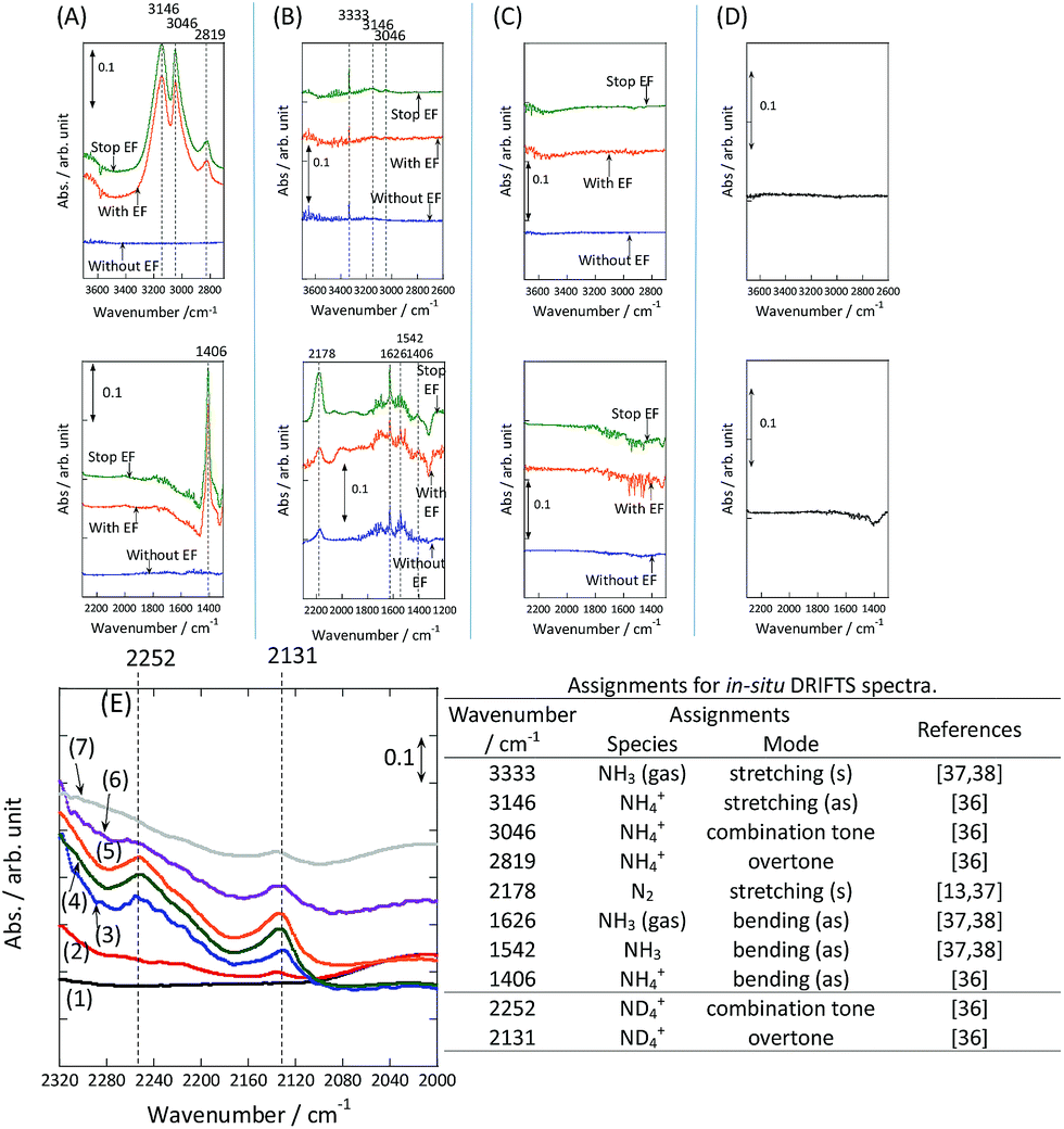
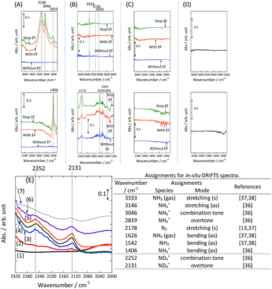
To observe the adsorbed species on the surface of the catalyst during application of the electric field for ammonia synthesis, and to reveal the mechanism of the ammonia synthesis reaction in the presence of the electric field, in situ diffuse reflectance infrared Fourier transform spectroscopy (DRIFTS) measurements were conducted. With a customized cell, we measured the IR spectrum when the electric field was applied to the catalyst bed, as presented in Fig. S2.† The obtained in situ DRIFTS spectra under each condition are shown in Fig. 3. Assignments are presented in the table in Fig. 3. As shown in Fig. 3(A), no peaks were observed when supplying only N2 and H2 at 473 K. However, when applying the electric field, four sharp peaks around 3146, 3046, 2819 and 1406 cm−1 were detected. These peaks were not observed under a pure N2 supply with the electric field (C), or during ammonia synthesis at 648 K without the electric field (D). Therefore, these four peaks were observed only when the electric field was applied to the catalyst bed. They were assigned to the stretching, combination tone, overtone and bending modes of N–H vibrations derived from NH4+.36 In addition, these species remained on the catalyst surface after cessation of the electric field. Presumably, NH4+ was produced from synthesized NH3 and protons. The protons are generated from H2 and hop on the catalyst surface when the electric field is applied. The ammonium cation only exists in a stable form on the catalyst. Fig. 3(E) shows the in situ DRIFTS spectra with D2. The peaks derived from the isotopes did not appear merely by supplying D2 to the produced ammonium ions (spectrum 2). However, upon application of the electric field, two peaks assigned to the combination tone and overtone modes of ND4+ were observed at around 2252 and 2131 cm−1 (spectrum 3).36 These peaks were weakened under H2 flow conditions in the presence of the electric field (spectrum 6). Based on the above observations, the protons are considered to hop via NH4+ ions and the catalyst support when the electric field is applied to the catalyst bed. The electric field could not be applied without supplying H2. Fig. 3(B) shows the in situ DRIFTS spectra while supplying NH3 at 473 K. Peaks derived from NH3 and N2 species were also detected at around 3333, 1626, 1542 and 2178 cm−1.13,37,38 However, peaks assignable to the N–H vibrations derived from NH4+ were very weak compared with those in Fig. 3(A), even when applying the electric field. These results show that surface protonics occur only when the forward reaction for ammonia synthesis proceeds in the presence of an electric field.
 |
| | Fig. 3
In situ DRIFTS spectra with, without, and after switching off the electric field (EF). (A) N2:H2 = 15:45 SCCM at 473 K; (B) 10% NH3/He:Ar = 1:59 SCCM at 473 K; (C) N2:Ar = 15:45 SCCM at 473 K; (D) N2:H2 = 15:45 SCCM at 648 K (without the EF, catalytic reaction); (E) experiments using an isotope (D2) at 473 K: (1) after imposing the EF with N2 and H2, (2) when D2 (15 SCCM) was supplied, (3) when D2 was supplied with the EF (10 mA), (4) after imposing the EF with D2, (5) when H2 (15 SCCM) was supplied again, (6) when H2 was supplied with the EF (10 mA), (7) after imposing the EF with H2 and the catalyst (9.9 wt% Cs/5.0 wt% Ru/SrZrO3; current, 0, 6, or 10 mA). | |
Theoretical calculations for ammonia synthesis with/without the electric field and the proposed mechanism of ammonia synthesis in the electric field
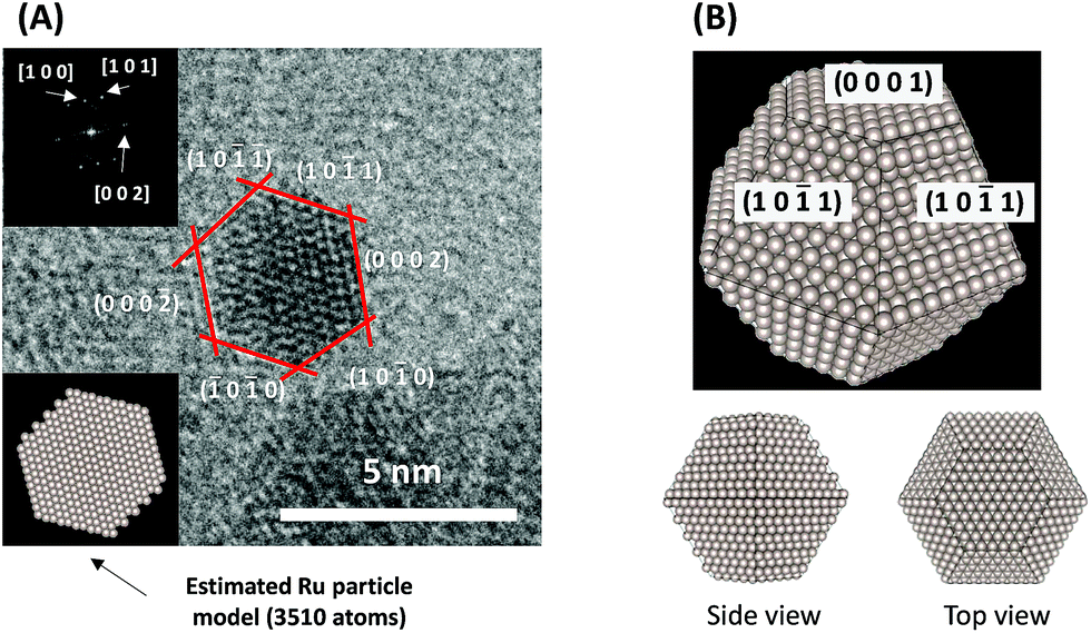
To consider the reaction mechanism experimentally and theoretically, we considered the (0001) and (10![[1 with combining macron]](https://www.rsc.org/images/entities/char_0031_0304.gif) 1) facets, which are the exposed facets at the surface of the Ru particles, as observed by the transmission electron microscope (TEM) images in Fig. 4.
1) facets, which are the exposed facets at the surface of the Ru particles, as observed by the transmission electron microscope (TEM) images in Fig. 4.
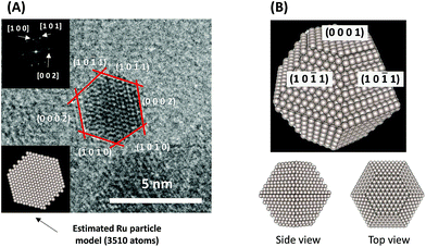 |
| | Fig. 4 (A) Representative TEM images of a Ru particle supported on SrZrO3 and (B) proposed models for the Ru particles. | |
To examine how the effect of an electric field on the Ru catalyst can be expressed by theoretical computation, the in situ IR spectra of CO adsorbed on Ru/SrZrO3 were measured (Fig. S3–S6†). The IR spectra with and without an electric field indicate that a blue shift of the CO vibrational frequency occurred when an electric field was applied to the Ru catalyst. Using density functional theory (DFT), the blue shift of the CO vibrational mode was observed to occur when positive charge was introduced into the system, irrespective of the facet and adsorption site (Table S2†). Thus, these results suggest that the effect of an electric field on Ru is well expressed by introducing positive charge into the system.
Next, the ammonia synthesis reaction under an applied electric field was theoretically considered. As suggested by the experimental results, the ammonia synthesis reaction under an applied electric field is significantly different from the conventional catalytic ammonia synthesis reaction, because in the former, protonics govern the reaction. Considering this, both the “dissociative mechanism”,
| | 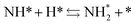 | (13) |
| |  | (14) |
| |  | (15) |
and the “associative mechanism”,
| |  | (19) |
| | 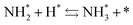 | (20) |
| | 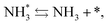 | (21) |
were examined using theoretical calculations.
39–42 Here, the asterisk (*) denotes a vacant surface site, and a species with an asterisk is an adsorbed species. The rate-determining steps of the dissociative and associative mechanisms were found to be N
2 dissociation and N
2H formation, respectively; thus the activation barriers and reaction energies for these two steps were examined.
Using the DFT method, the reaction energies (ΔE) of the N2 dissociation and N2H formation reactions were calculated (Fig. 5). The results show that the application of an electric field, which is simulated by the positive charge in the system, induces an increase in ΔE for N2 dissociation but a decrease in ΔE for N2H formation. As a result, without an electric field, the formation of N2H is an endothermic process but it becomes an exothermic process under an applied electric field. The calculated activation energies (Ea) of these processes (Fig. S7(A)†) also indicate that N2H is more easily formed when an electric field is applied; Ea significantly decreased from 0.93 eV (N2 dissociation) to 0.61 eV (N2H formation) when 15 positive charges were introduced into the computational model. Here, the Ea values on Ru(101) were used because this surface has a larger area in the assumed Ru particle (Fig. 4). This explains the significant decrease of the activation energy with the application of an electric field.
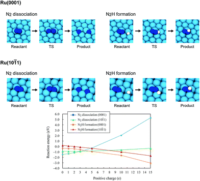 |
| | Fig. 5 Optimized structures of the reactant state, transition state (TS) and product state of the N2 dissociation and N2H formation reactions on Ru(0001) and Ru(101), the reaction energies of the N2 dissociation and N2H formation reactions on Ru(0001) and Ru(101), and their dependence on the electric field strength, expressed by the magnitude of the positive charge. On Ru(0001), the dissociated N atoms occupy fcc and hcp hollow sites, and N2H formation generates N2H adsorbed on hcp sites. On Ru(101), both the dissociated N atoms and generated N2H occupy four-fold hollow sites. | |
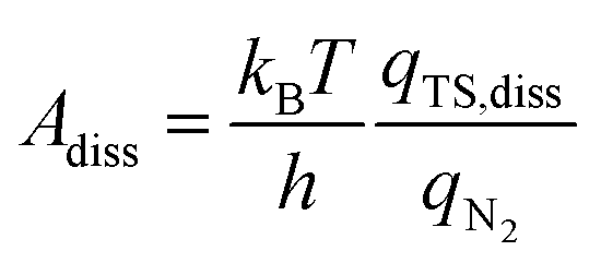
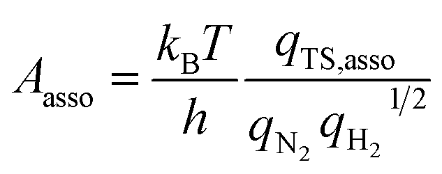
In addition to the activation energy, the experimental Arrhenius plot in Fig. 1(B) suggests that the application of an electric field causes a large decrease in the pre-exponential factor. Interestingly, based on transition state theory, the pre-exponential factors for the dissociative and associative mechanisms are very different because they are calculated as
| | 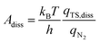 | (22) |
and
| | 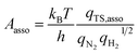 | (23) |
respectively, where
kB and
h are the Boltzmann and Planck constants,
qN2 and
qH2 are the molecular partition functions for N
2 and H
2, and
qTS,diss and
qTS,asso are the molecular partition functions for the transition states of the dissociative and associative mechanisms. The presence of
qH2 in the denominator of
eqn (23) makes
Aasso smaller than
Adiss by 4.5 × 10
2.
Based on these pre-exponential factors and calculated activation energies, a theoretical Arrhenius plot can be constructed (Fig. S7(B)†). Our theoretical plot can explain two important differences between the experimental plots with and without an electric field, when an associative mechanism is assumed for the ammonia synthesis reaction under an applied electric field. Thus, our calculation assuming the associative mechanism explains both the large decreases in Ea and the pre-exponential factor. This strongly suggests that the ammonia synthesis reaction with and without an electric field proceeds via different mechanisms, i.e. dissociative and associative mechanisms, respectively.
Our experimental and theoretical investigations demonstrated that proton hopping in an electric field on the catalyst surface plays an important role in N2 activation at low temperatures. The proposed mechanism for ammonia synthesis in an electric field is presented in Fig. 6. The peculiar surface conduction caused by the electric field, proton hopping, is considered to enable ammonia synthesis to proceed at low temperatures and atmospheric pressure.
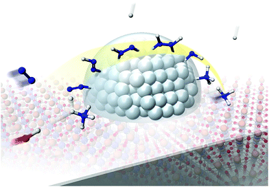 |
| | Fig. 6 Schematic illustrating the mechanism of the ammonia synthesis reaction in an electric field. | |
Conclusions
Ammonia synthesis was performed over a 9.9 wt% Cs/5.0 wt% Ru/SrZrO3 catalyst in an electric field under various pressures. The ammonia synthesis activity of this catalyst increased drastically upon application of the electric field under both atmospheric and 0.9 MPa pressure, even at low reaction temperatures. The maximum ammonia yield per gram of catalyst was 30099 μmol g−1 h−1, which is the highest value reported to date. To elucidate the effects of the electric field on ammonia synthesis, a kinetic investigation and in situ DRIFTS measurements were conducted under atmospheric pressure. The results of our kinetic analyses demonstrated that both the apparent activation energy and the dependence of the reaction rate on N2 pressure decreased upon application of the electric field, indicating that clearly different reaction mechanisms occur with and without application of the electric field. Furthermore, isotope exchange tests demonstrated that N2 dissociative adsorption was markedly promoted by application of the electric field. The in situ DRIFTS results revealed that proton conduction via NH4+ and the catalyst support occurred when the electric field was applied. These unique surface protonics are strongly associated with N2 activation, which moderates the severe conditions required for ammonia synthesis. The mechanism of ammonia synthesis in an electric field proposed here was also supported by theoretical calculations, demonstrating that the mechanism changed from dissociative to associative upon application of the electric field. In summary, surface protonics induced by the application of an electric field have an important role to play in the enhancement of catalytic ammonia synthesis under mild conditions.
Acknowledgements
R. M. acknowledges the Leading Graduate Program in Science and Engineering, Waseda University, supported by MEXT, Japan. Analyses of TEM images were mainly conducted by Dr Kei Mukawa. This research was partially supported financially by the JST-CREST.
References
- U. B. Demirci and P. Miele, Energy Environ. Sci., 2011, 4, 3334 CAS.
- H. Stoltze and J. K. Nerskiv, Phys. Rev. Lett., 1985, 55(22), 2502 CrossRef PubMed.
- C. J. H. Jacobsen, Chem. Commun., 2000, 12, 1057 RSC.
- G. Ertl,
et al.
, J. Catal., 1983, 79, 359 CrossRef CAS.
- K. Aika,
et al.
, J. Catal., 1972, 27, 424 CrossRef CAS.
- K. Aika,
et al.
, J. Catal., 1985, 92, 305 CrossRef CAS.
- O. Hinrichsen, Catal. Today, 1999, 53, 177 CrossRef CAS.
- F. Rosowski,
et al.
, Appl. Catal., A, 1997, 151, 443 CrossRef CAS.
- S. E. Siporin and R. J. Davis, J. Catal., 2004, 225, 359 CrossRef CAS.
- Z. Wang,
et al.
, Appl. Catal., A, 2013, 458, 130 CrossRef CAS.
- H. Bielawa,
et al.
, Angew. Chem., Int. Ed., 2001, 40, 1061 CrossRef CAS PubMed.
- K. Sato,
et al.
, Chem. Sci., 2017, 8, 674 RSC.
- M. Kitano,
et al.
, Nat. Chem., 2012, 4, 934 CrossRef CAS PubMed.
- M. Kitano,
et al.
, Nat. Commun., 2015, 6, 1 Search PubMed.
- M. Kitano,
et al.
, Chem. Sci., 2016, 7, 4036 RSC.
- Y. Inoue,
et al.
, ACS Catal., 2016, 6, 7577 CrossRef CAS.
- Y. Tanabe and Y. Nishibayashi, Coord. Chem. Rev., 2013, 257, 2551 CrossRef CAS.
- K. Arashiba,
et al.
, Nat. Chem., 2011, 3, 120 CrossRef CAS PubMed.
- S. Kuriyama,
et al.
, Nat. Commun., 2016, 7, 1 Search PubMed.
- S. Kuriyama,
et al.
, Angew. Chem., Int. Ed., 2016, 55, 14291 CrossRef CAS PubMed.
- T. Shima,
et al.
, Science, 2013, 340, 1549 CrossRef CAS PubMed.
- L. M. Dmitrenko,
et al.
, Kinet. Catal., 1960, 1, 352 Search PubMed.
- K. Aihara,
et al.
, Chem. Commun., 2016, 52, 13560 RSC.
- M. Bai,
et al.
, Plasma Chem. Plasma Process., 2008, 28, 405 CrossRef CAS.
- H. Uyama and O. Matsumoto, Plasma Chem. Plasma Process., 1989, 9(1), 13 CrossRef CAS.
- H. Uyama and O. Matsumoto, Plasma Chem. Plasma Process., 1989, 9(3), 421 CrossRef CAS.
- K. S. Yin and M. Venugopalan, Plasma Chem. Plasma Process., 1983, 3(3), 343 CrossRef CAS.
- H. Kiyooka and O. Matsumoto, Plasma Chem. Plasma Process., 1996, 16(4), 547 CrossRef CAS.
- S. Sun,
et al.
, Appl. Catal., B, 2017, 200, 323 CrossRef CAS.
- G. Marnellos and M. Stoukides, Science, 1998, 282, 98–100 CrossRef CAS PubMed.
- K. Aika and A. Ozaki, J. Catal., 1969, 13, 232 CrossRef CAS.
- K. Aika,
et al.
, Appl. Catal., 1986, 28, 57 CrossRef CAS.
- S. Hagen,
et al.
, J. Catal., 2003, 214, 327 CrossRef CAS.
- Y. Morikawa and A. Ozaki, J. Catal., 1971, 23, 97 CrossRef CAS.
- K. Urabe,
et al.
, J. Catal., 1974, 32, 108 CrossRef CAS.
- E. L. Wagner and D. F. Hornig, J. Phys. Chem., 1950, 18, 296 CrossRef CAS.
- J. A. Herron,
et al.
, Surf. Sci., 2013, 614, 64 CrossRef CAS.
- H. Shi,
et al.
, J. Chem. Phys., 1995, 102, 1432 CrossRef CAS.
- S. Dahl,
et al.
, Phys. Rev. Lett., 1999, 83(9), 1814 CrossRef.
- K. Honkala,
et al.
, Science, 2005, 307(5709), 555 CrossRef CAS PubMed.
- T. H. Rod,
et al.
, J. Chem. Phys., 2000, 112(12), 5343 CrossRef CAS.
- A. L. Garden and E. Skulason, J. Phys. Chem. C, 2015, 119(47), 26554 CAS.
Footnote |
| † Electronic supplementary information (ESI) available. See DOI: 10.1039/c7sc00840f |
|
| This journal is © The Royal Society of Chemistry 2017 |
Click here to see how this site uses Cookies. View our privacy policy here. 
 Open Access Article
 This Open Access Article is licensed under a
  *a
*a