
 Open Access Article
 This Open Access Article is licensed under a
 Creative Commons Attribution 3.0 Unported Licence
Evaluating the electronic structure of formal LnII ions in LnII(C5H4SiMe3)31− using XANES spectroscopy and DFT calculations†
Megan E.
Fieser‡
 a,
Maryline G.
Ferrier‡
b,
Jing
Su‡
b,
Enrique
Batista
*b,
Samantha K.
Cary
b,
Jonathan W.
Engle
bc,
William J.
Evans
*a,
Juan S.
Lezama Pacheco
d,
Stosh A.
Kozimor
*b,
Angela C.
Olson
b,
Austin J.
Ryan
a,
Benjamin W.
Stein
b,
Gregory L.
Wagner
b,
David H.
Woen
a,
Tonya
Vitova
e and
Ping
Yang
*b
a,
Maryline G.
Ferrier‡
b,
Jing
Su‡
b,
Enrique
Batista
*b,
Samantha K.
Cary
b,
Jonathan W.
Engle
bc,
William J.
Evans
*a,
Juan S.
Lezama Pacheco
d,
Stosh A.
Kozimor
*b,
Angela C.
Olson
b,
Austin J.
Ryan
a,
Benjamin W.
Stein
b,
Gregory L.
Wagner
b,
David H.
Woen
a,
Tonya
Vitova
e and
Ping
Yang
*b
aUniversity of California, Irvine, CA 92697, USA. E-mail: wevans@uci.edu
bLos Alamos National Laboratory, Los Alamos, NM 87545, USA. E-mail: stosh@lanl.gov; pyang@lanl.gov; erb@lanl.gov
cUniversity of Wisconsin, Madison, Wisconsin 53711, USA
dStanford University, Palo Alto, CA 94305, USA
eKarlsruhe Institute of Technology, Institute for Nuclear Waste Disposal, P.O. Box 3640, 76021 Karlsruhe, Germany
First published on 30th June 2017
Abstract
The isolation of [K(2.2.2-cryptand)][Ln(C5H4SiMe3)3], formally containing LnII, for all lanthanides (excluding Pm) was surprising given that +2 oxidation states are typically regarded as inaccessible for most 4f-elements. Herein, X-ray absorption near-edge spectroscopy (XANES), ground-state density functional theory (DFT), and transition dipole moment calculations are used to investigate the possibility that Ln(C5H4SiMe3)31− (Ln = Pr, Nd, Sm, Gd, Tb, Dy, Y, Ho, Er, Tm, Yb and Lu) compounds represented molecular LnII complexes. Results from the ground-state DFT calculations were supported by additional calculations that utilized complete-active-space multi-configuration approach with second-order perturbation theoretical correction (CASPT2). Through comparisons with standards, Ln(C5H4SiMe3)31− (Ln = Sm, Tm, Yb, Lu, Y) are determined to contain 4f6 5d0 (SmII), 4f13 5d0 (TmII), 4f14 5d0 (YbII), 4f14 5d1 (LuII), and 4d1 (YII) electronic configurations. Additionally, our results suggest that Ln(C5H4SiMe3)31− (Ln = Pr, Nd, Gd, Tb, Dy, Ho, and Er) also contain LnII ions, but with 4fn 5d1 configurations (not 4fn+1 5d0). In these 4fn 5d1 complexes, the C3h-symmetric ligand environment provides a highly shielded 5d-orbital of a′ symmetry that made the 4fn 5d1 electronic configurations lower in energy than the more typical 4fn+1 5d0 configuration.
Introduction
Recent advances in rare-earth metal reduction chemistry have revealed a surprisingly new series of molecular complexes that contained all the rare earth metals in the formal oxidation state of +2,1 as defined by Parkin and Karen, (Scheme 1).2,3 These results were unexpected given that the +2 oxidation state had only been observed with six rare earth metals in molecules (Eu, Yb, Sm, Tm, Dy, and Nd). Observing this +2 oxidation state for the other lanthanides was unexpected because the −2.7 to −3.9 V versus standard hydrogen electrode (SHE) LnIII/LnII reduction potentials seemed too negative to allow LnII ions to exist in solution.4 In the solid state, only the six lanthanides listed above were known to form +2 salts. For the other metals, compounds like LnX2 (Ln = La, Ce, Pr, Gd, and Y; X = halide) with formal +2 oxidation states had been observed, but subsequent analyses revealed that they contain +3 ions and a delocalized electron in a conduction band, i.e. LnIII(X1−)2(e1−).5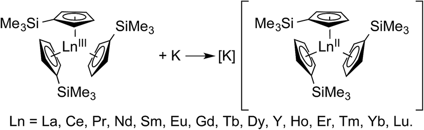 | ||
| Scheme 1 A general reaction scheme for generating LnII(C5H4SiMe3)31− containing salts. Accessing these compounds in crystalline form requires complexation of the potassium cation by 18-crown-6 or 2.2.2-cryptand.1 | ||
The new Ln(C5H4SiMe3)31− compounds, containing the putative +2 ions, were synthesized by potassium reduction of trimethylsilylcylopentadienyl lanthanide(III) complexes, Ln(C5H4SiMe3)3 (Scheme 1). More detailed synthetic descriptions for these Ln(C5H4SiMe3)31− anions, as well as related Ln[C5H3(SiMe3)2]31− complexes prepared by Lappert and coworkers, have been previously discussed.6 The new Ln(C5H4SiMe)31− complexes were unusual in that their Ln–Ccentroid distances were only 1% (0.020–0.032 Å) longer than their LnIII precursors, Ln(C5H4SiMe3)3. Larger variations, by an order of magnitude (0.1 to 0.2 Å), were expected based on previous comparisons between conventional LnIIversus LnIII structures, which historically provided a diagnostic for the +2 oxidation state. Consistent with this traditional expectation, Ln(C5H4SiMe3)31− bond lengths for Ln = Eu, Yb, Sm, and Tm were 0.10–0.20 Å (∼6%) longer than their +3 analogs.7 The unusually short bond lengths in the La, Ce, Pr, Nd, Gd, Tb, Dy, Y, Ho, Er, and Lu complexes led to skepticism about the presence of the +2 oxidation state across the Ln(C5H4SiMe3)31− series, suggesting that the salts might contain +3 metals with an electron delocalized into ligand-based orbitals. This scenario was – in a sense – reminiscent of the LnX2 compounds (discussed above).5 An alternative description, based on subsequent theoretical analyses, proposed that the small differences in bond distances for La, Ce, Pr, Nd, Gd, Tb, Dy, Y, Ho, Er, and Lu complexes were a direct result of the metal ions having an unusual 4fn 5d1 electronic configuration, rather than the traditionally expected 4fn+1 5d0 configuration known for EuII, YbII, SmII, and TmII.
Attempts have been made to validate the theoretical conclusions using electronic absorption spectroscopy and magnetic susceptibility.8 Although the UV-vis analyses showed intense bands that were consistent with the 4fn 5d1 configurations, forbidden 4f → 4f transitions typically used as diagnostics for lanthanide oxidations states were not experimentally resolved.1,5,9 Similarly, the magnetic studies showed complicated magnetic behavior that could not be ubiquitously rationalized for all the lanthanides using simple models.8d For these reasons, it was of great interest to evaluate the electronic structure of the Ln(C5H4SiMe3)31− complexes using a combination of X-ray absorption near-edge spectroscopy (XANES) and transition dipole moment density functional theory (DFT). There is an emerging body of literature demonstrating the power of cooperative XANES and DFT analyses in evaluating bonding and electronic structure in inorganic compounds.10 As such, we have recently used this approach to uniquely characterize the electronic structures of a wide variety of f-element species.11
Herein, we describe the use of a combination of XANES and transition dipole moment DFT calculations to evaluate the possibility that the LnII(C5H4SiMe3)31− (Ln = Pr, Nd, Sm, Gd, Tb, Dy, Y, Ho, Er, Tm, Yb and Lu) compounds represent molecular LnII complexes. In the XANES experiment, an analyte is exposed to high-energy X-rays that excite core electrons to higher, unoccupied states. At the Ln L3,2-edges, there is an edge-jump consisting of electric-dipole allowed transitions from Ln 2p-orbitals to unoccupied states that contain metal d-character. Moving to higher energies, core electrons are excited into the continuum (Scheme 2). Given that Ln L3,2-edge XANES probes transitions to Ln 5d-orbitals, this spectroscopic approach provides a particularly sensitive and accurate method for directly characterizing 5d-orbital occupancies for the alleged 4fn 5d1 ions in Ln(C5H4SiMe3)31− (Ln = La, Ce, Pr, Nd, Gd, Tb, Dy, Ho, Er, and Lu) anions. To guide interpretations of these XANES spectra, appropriate ground-state DFT models were developed that formed a basis for extracting probability amplitudes from the transition dipole moments between the calculated excited-states and the ground-state. Combined, these computational and experimental efforts allow the influence of 4fn+1 5d0versus 4fn 5d1 electronic configurations on the lanthanide L3-edge XANES spectra to be determined for the first time.
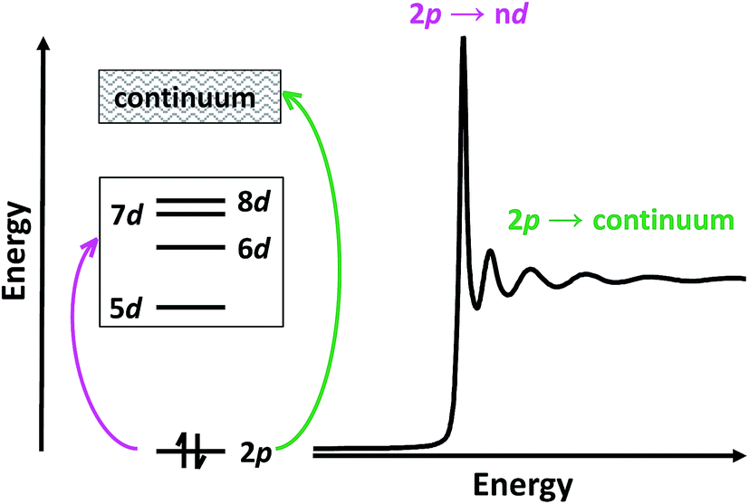 | ||
| Scheme 2 Cartoon depicting the origin of L3-edge XANES transitions. | ||
To best characterize the electronic structure of the [K(2.2.2-cryptand)][Ln(C5H4SiMe3)3] salts containing new LnII ions, XANES and DFT studies are also reported with the compounds containing traditional +2 ions (i.e. SmII, TmII, and YbII) whose electronic configurations were well defined as 4f6, 4f13, and 4f14, respectively. These results provide a foundation for analyses of the other Ln(C5H4SiMe3)31− anions. For comparison, studies of the neutral 4fn 5d0 LnIII complexes, Ln(C5H4SiMe3)3, are also reported because the metal oxidation state in these compounds is unambiguously +3. These combined efforts lead to a definitive description of the electronic structure and bonding in the Ln(C5H4SiMe3)31− complexes. For the convenience of the reader in the rest of the paper, we refer to compounds with formal +3 oxidation states as LnIII(C5H4SiMe3)3 and formal +2 oxidation states as LnII(C5H4SiMe3)1−. When discussing both, the Roman numerals are omitted and Ln(C5H4SiMe3)3x− (x = 0, 1) is used.
Results
Sm L3,2-edge XANES
The background-subtracted and normalized Sm L3,2-edge XANES spectra from [K(2.2.2-cryptand)][SmII(C5H4SiMe3)3] and SmII(C5Me5)2(THF)2 are shown in Fig. 1. Each spectrum contains large edge features near 6715 eV (L3) and 7310 eV (L2) and small post-edge shoulders near 6725 and 7320 eV that are superimposed on step-like absorption thresholds. The L3,2-edge positions were characterized by their peak maxima, where the first derivatives of the data equaled zero (Table 1). Given the sharp characteristics of these peaks, we find that the peak maximum provides a more useful metric than the inflection point, which is commonly used to evaluate actinide absorption edges. The L3,2-edge peak maxima for SmII(C5H4SiMe3)31− at 6715.6 and 7311.1 eV are nearly identical to the 6715.2 and 7310.7 eV values determined for SmII(C5Me5)2(THF)2 and similar to the other SmII L3,2-edge XANES spectra reported previously (Table 1).12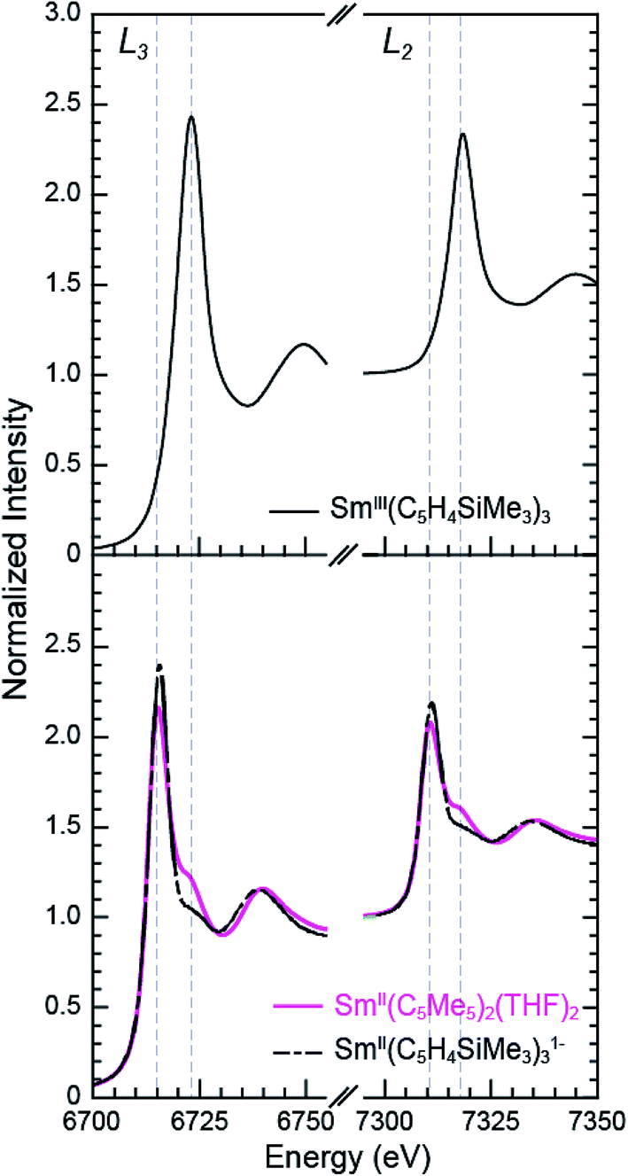 | ||
| Fig. 1 The background-subtracted and normalized Sm L3,2-edge XANES spectra obtained from SmIII(C5H4SiMe3)3 (top, black trace), SmII(C5Me5)2(THF)2 (bottom, pink trace), and [K(2.2.2-cryptand)][SmII(C5H4SiMe3)3] (bottom, black dashed trace). | ||
| Compound | Edge | Peak position (eV)a | Δ(LnIII–LnII) peak position (eV) |
|---|---|---|---|
| a The peak position points were defined as the first point at which the first derivative of the data equaled zero. b Because the yttrium measurements were made at the Y K-edge, inflection points for YIII(C5H4SiMe3) and [K(2.2.2-cryptand)][YII(C5H4SiMe3)] are reported. | |||
| PrII(C5H4SiMe3)31− | L2 | 6444.5 | 0.2 |
| PrIII(C5H4SiMe3)3 | L2 | 6444.7 | |
| NdII(C5H4SiMe3)31− | L2 | 6728.5 | 0.3 |
| NdIII(C5H4SiMe3)3 | L2 | 6728.8 | |
| SmII(C5H4SiMe3)31− | L3 | 6715.6 | 7.6 |
| L2 | 7311.1 | 7.3 | |
| SmIII(C5H4SiMe3)3 | L3 | 6723.2 | |
| L2 | 7318.4 | ||
| SmII[N(SiMe3)2](THF)2 | L3 | 6715.0 | 7.8 |
| SmIII[N(SiMe3)2]3 | L3 | 6722.8 | |
| SmII(C5Me5)2(THF)2 | L3 | 6715.2 | — |
| L2 | 7310.7 | ||
| GdII(C5H4SiMe3)31− | L3 | 7248.6 | 0.3 |
| GdIII(C5H4SiMe3)3 | L3 | 7248.9 | |
| TbII(C5H4SiMe3)31− | L3 | 7520.3 | 0.9 |
| L2 | 8258.1 | 1.0 | |
| TbIII(C5H4SiMe3)3 | L3 | 7521.2 | |
| L2 | 8259.1 | ||
| DyII(C5H4SiMe3)31− | L3 | 7798.1 | 0.4 |
| DyIII(C5H4SiMe3)3 | L3 | 7798.5 | |
| HoII(C5H4SiMe3)31− | L3 | 8075.6 | 0.5 |
| L2 | 8922.3 | 0.3 | |
| HoIII(C5H4SiMe3)3 | L3 | 8076.1 | |
| L2 | 8922.6 | ||
| ErII(C5H4SiMe3)31− | L3 | 8364.0 | 0.5 |
| ErIII(C5H4SiMe3)3 | L3 | 8364.5 | |
| TmII(C5H4SiMe3)31− | L3 | 8647.5 | 7.0 |
| L2 | 9617.1 | 6.6 | |
| TmIII(C5H4SiMe3)3 | L3 | 8654.5 | |
| L2 | 9623.7 | ||
| TmIII2(THF)3 | L3 | 8646.3 | 7.7 |
| L2 | 9616.0 | 7.0 | |
| TmIIII3(THF)3.5 | L3 | 8653.8 | |
| L2 | 9623.0 | ||
| YbII(C5H4SiMe3)31− | L3 | 8942.7 | 7.3 |
| YbIII(C5H4SiMe3)3 | L3 | 8950.0 | |
| LuII(C5H4SiMe3)31− | L3 | 9244.4 | 1.9 |
| LuIII(C5H4SiMe3)3 | L3 | 9246.3 | |
| YII(C5H4SiMe3)31− | K | 17![[thin space (1/6-em)]](https://www.rsc.org/images/entities/char_2009.gif) 052.6,a 17047.3b 052.6,a 17047.3b |
1.0 |
| YIII(C5H4SiMe3)3 | K | 17053.6,a 17048.7b |
|
The Sm L3,2-edge XANES spectra obtained from SmII(C5H4SiMe3)31− and SmII(C5Me5)2(THF)2 are also compared with SmIII(C5H4SiMe3)3 in Fig. 1. The SmIII(C5H4SiMe3)3 L3,2-edge spectra differ from the SmII spectra in that the edge features are shifted by approximately 7–8 eV to higher energies at 6723.2 and 7318.4 eV, Table 1. The differences in edge-positions for 4f6 5d0 (+2) and 4f5 5d0 (+3) samarium species are not unique to this suite of samarium cyclopentadienyl compounds.10,13 For instance, the Sm L3-edge XANES spectra obtained from SmII[N(SiMe3)2]2(THF)2 and SmIII[N(SiMe3)2]3, also exhibit a Sm L3-edge energy difference of 7–8 eV (Fig. 2 and Table 1). These results demonstrate that samarium 4f-orbital occupancy (4f6 5d0versus 4f5 5d0) influences the peak position more substantially than the ligand identity, as changing cyclopentadienide in SmIII(C5H4SiMe3)3 to amido ligands in SmIII[N(SiMe3)2]3 only shifts the L3-edge peak maximum to lower energy by 0.4 eV.
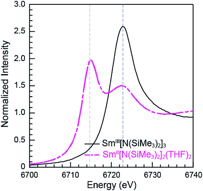 | ||
| Fig. 2 The background-subtracted and normalized Sm L3-edge XANES measurements obtained from the SmIII[N(SiMe3)2]3 (black trace) and SmII[N(SiMe3)2]2(THF)2 (pink dashed trace). | ||
Comparisons between the SmII and SmIII spectra provide insight into the origin of the small post-edge shoulders near 6725 and 7320 eV observed in all of the SmII spectra. As shown by the dashed lines in Fig. 1 and 2, this post-edge feature corresponds to the peak maximum of SmIII. While the magnitude of this feature is invariant with temperature between 8 and 100 K, it shows significant intensity changes during our attempts to reproduce the data, e.g. from sample-to-sample. Hence, we attribute this feature to a small amount of SmIII contamination, which likely arose from unwanted reactions with small amounts of O2 or H2O. Despite our best attempts, we were unsuccessful in obtaining completely pure SmII spectra; (1) analytes were shipped to the synchrotron cold and under vacuum, (2) XANES-samples were prepared at low temperature with rigorous exclusion of air and moisture immediately before the experiment, and (3) measurements were obtained rapidly (low temperature, under vacuum) using an unfocused beam. While it is difficult to identify what caused this contamination, the decomposition rate from X-ray radiolysis under our experimental conditions is slow. For example, when samples are cooled under vacuum (8 to 100 K; 10−7 Torr), the SmII spectra are unchanged after 3 hours of exposure to X-rays using an unfocused beam on SSRL's beam line 11-2. These results suggest that the SmIII species is not being generated during the XANES data acquisition. However, we identified under different experimental conditions – using a focused beam at room temperature under an argon atmosphere on SSRL's beam line 6-2 – that complete conversion of SmII(C5H4SiMe3)31− to SmIII occurred in less than 10 seconds.
Tm and Yb L3,2-edge XANES
The background-subtracted and normalized Tm L3,2-edge XANES spectra from +2 and +3 thulium compounds are shown in Fig. 3. As observed for the samarium compounds in Fig. 1 and 2, spectra from the [K(2.2.2-cryptand)][TmII(C5H4SiMe3)3] and TmIII2(THF)3 compounds display two main features. There are pronounced peaks near 8645 eV (L3) and 9615 eV (L2) and higher energy post-edge shoulders at approximately 8655 eV and 9625 eV. Comparisons with +3 thulium compounds – namely, TmIII(C5H4SiMe3)3 and TmIIII3(THF)3.5 – lead us to interpret the TmII spectra in analogy to the SmII results described above. For instance, the large edge-features for TmII(C5H4SiMe3)31− and TmIII2(THF)3 are about 7 eV lower in energy than the edge features from TmIII(C5H4SiMe3)3 and TmIIII3(THF)3.5, Table 1. The spectral shapes and the trend toward lower energy for the LnII L3-edges from Ln(C5H4SiMe3)3x− (Ln = Tm, Sm; x = 0, 1) are consistent with models of the data generated using quantum chemical ab initio FEFF9.6 code based on the multiple scattering theory (see Fig. S1 and S2†).14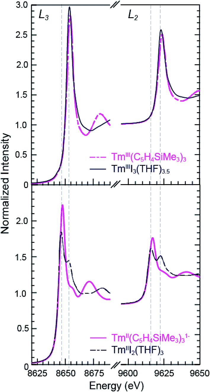 | ||
| Fig. 3 The background-subtracted and normalized Tm L3,2-edge XANES spectra obtained from TmIII(C5H4SiMe3)3 (top, pink dashed trace), TmI3(THF)3.5 (top, black trace), [K(2.2.2-cryptand)][TmII(C5H4SiMe3)3] (bottom, pink trace), and TmI2(THF)3 (bottom, black dashed trace). | ||
As observed in the SmII L3,2-edge XANES experiments, the TmII spectra contain post-edge shoulders associated with small amounts of +3 thulium contamination. Variable temperature XANES experiments conducted between 8 and 100 K on these thulium compounds using a small excitation beam (1 × 1 mm) that was rastered across the sample show small variations in peak intensities. However, because the changes are not reversible and not reproducible, we attribute the slight variances to sample decomposition. Nevertheless, the compounds seem quite stable to X-ray radiation damage on the XANES experimental time scale (10 s to 1.5 h) under our experimental conditions; low temperature (8–100 K), under vacuum (10−7 Torr), and in an unfocused beam on SSRL's beam line 11-2.
Despite minor LnIII contamination in the SmII and TmII spectra, these results provide confidence and credibility in our abilities to manipulate extremely air and moisture sensitive organometallic complexes at the SSRL synchrotron facility. We remind the reader of the sensitivity of the LnIII(C5H4SiMe3)3 compounds to hydrolysis, the highly reducing nature of SmII and TmII (which have standard reduction potentials of −1.5 and −2.3 V versus SHE),4 and of the light sensitivity of TmIIII3(THF)3.5. As noted previously,12,15 the consistent 7–8 eV shift between LnII and LnIII containing compounds highlights the utility of overcoming these sample handling challenges for characterizing TmII 4f13 5d0versus TmIII 4f12 5d0 electronic configurations using L3,2-edge XANES spectroscopy. Note that while not explicitly described here in detail, Fig. 4 shows that similar results were observed for ytterbium, whose spectrum, also displayed a peak maxima shift of ∼7 eV upon moving from YbII (4f14 5d0) to YbIII (4f13 5d0).
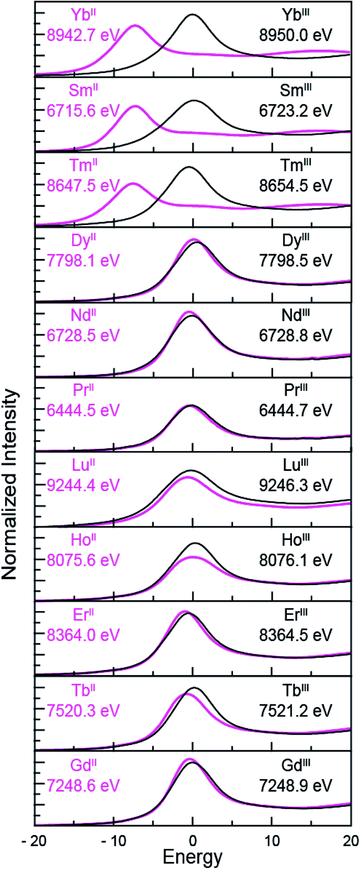 | ||
| Fig. 4 The background-subtracted and normalized L-edge XANES spectra obtained from LnIII(C5H4SiMe3)3 (black traces) and [K(2.2.2-cryptand)][LnII(C5H4SiMe3)3] (pink traces) for Ln = Yb, Sm, Tm, Dy, Nd, Pr, Lu, Ho, Er, Tb and Gd. All spectra were collected at the Ln L3-edge except Nd and Pr, which were collected at the L2-edge. Peak maxima are shown in each pane. The spectra have been ordered from top to bottom based on increasing general reduction potentials.4,16 | ||
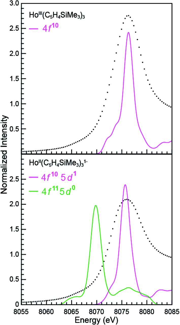
LnII(C5H4SiMe3)31− Ln L3,2-edge (Ln = Pr, Nd, Gd, Tb, Dy, Ho, and Er) XANES
The samarium, thulium, and ytterbium L3,2-edge measurements described above provide an experimental basis for using XANES spectroscopy to evaluate the recently discovered LnII(C5H4SiMe3)31− (Ln = Pr, Nd, Gd, Tb, Dy, Ho, and Er) compounds.1a,1b,8Fig. 4 compares the background-subtracted and normalized Ln L3- or L2-edge XANES spectra from [K(2.2.2-cryptand)][LnII(C5H4SiMe3)3] with LnIII(C5H4SiMe3)3. In this figure, the spectra are ordered from top to bottom as a function of increasing standard reduction potential, as determined by Morss and Mikheev.4,16 These data display rising-edge features similar to the samarium and thulium spectra described above. However, in stark contrast to the samarium, thulium, and ytterbium spectra, the L-edge peak maxima from the other LnII(C5H4SiMe3)31− anions are quite similar in energy to the neutral LnIII(C5H4SiMe3)3 compounds. As shown in Fig. 4 and Table 1, small shifts in L3-edge inflection points are observed for the other Ln(C5H4SiMe3)3x− (x = 0, 1) compounds, ranging from 0.2 to 1.0 eV.To evaluate the likelihood that the spectra obtained from LnII(C5H4SiMe3)31− (Ln = Pr, Nd, Gd, Tb, Dy, Ho, and Er) compounds were indeed correct, a series of control experiments were conducted. Herein we limit the discussion explicitly to the HoII/HoIII case. The first control experiment involved analyzing the HoII and HoIII samples by electronic absorption spectroscopy before and after the Ho L3,2-edge XANES experiment. Because the HoII(C5H4SiMe3)31− UV-vis spectrum is distinct from the HoIII(C5H4SiMe3)3 precursor, electronic absorption spectroscopy provides a robust method for confirming the presence of HoII(C5H4SiMe3)31− during the XANES experiment. First, an aliquot of HoII(C5H4SiMe3)31− was characterized by UV-visible spectroscopy (black trace, Fig. 5; pre-XANES). The spectrum showed the characteristic and broad charge transfer band associated with HoII(C5H4SiMe3)31−. Moreover, no detectible HoIII was observed. For comparison, the spectrum from HoIII(C5H4SiMe3)3 is shown as a gray trace. A second aliquot of the HoII(C5H4SiMe3)31− was diluted in BN and the Ho L3,2-edge XANES experiment was conducted. Subsequently, the sample – HoII(C5H4SiMe3)31− and BN – was transferred to a Teflon sealable quartz cuvette and the mixture was again characterized by UV-visible spectroscopy (pink trace, post-XANES). Unfortunately, because of constraints associated with the XANES holder, this transfer was not quantitative and the overall amount of HoII(C5H4SiMe3)31− in the cuvette was unknown. A 20% loss during the transfer is possible. Hence, the intensities in the pre-XANES spectrum cannot be directly compared with those from the post-XANES spectrum. Additionally, the BN in the post-XANES spectrum is insoluble and artificially increases the overall UV-visible baseline due to scattering effects. For data comparison, the post-XANES spectrum was background-subtracted to place overall peak heights on the same approximate absorbance scale. Regardless, this experiment unambiguously demonstrates that no detectable amount of HoIII(C5H4SiMe3)3 was observed before or after the synchrotron experiment. One cannot rule out the possibility of insoluble HoIII contaminates. For example, exposing a Teflon sealable cuvette containing the HoII(C5H4SiMe3)31− post-XANES samples to air for 2 s caused an immediate loss of HoII signal and no ingrowth of HoIII 4f → 4f transitions. However, when one considers loss of sample during the transfer from the XANES holder to the cuvette, this control experiment suggests that after the Ho L3,2-edge experiment >80% of the sample was in the form of HoII(C5H4SiMe3)31−.
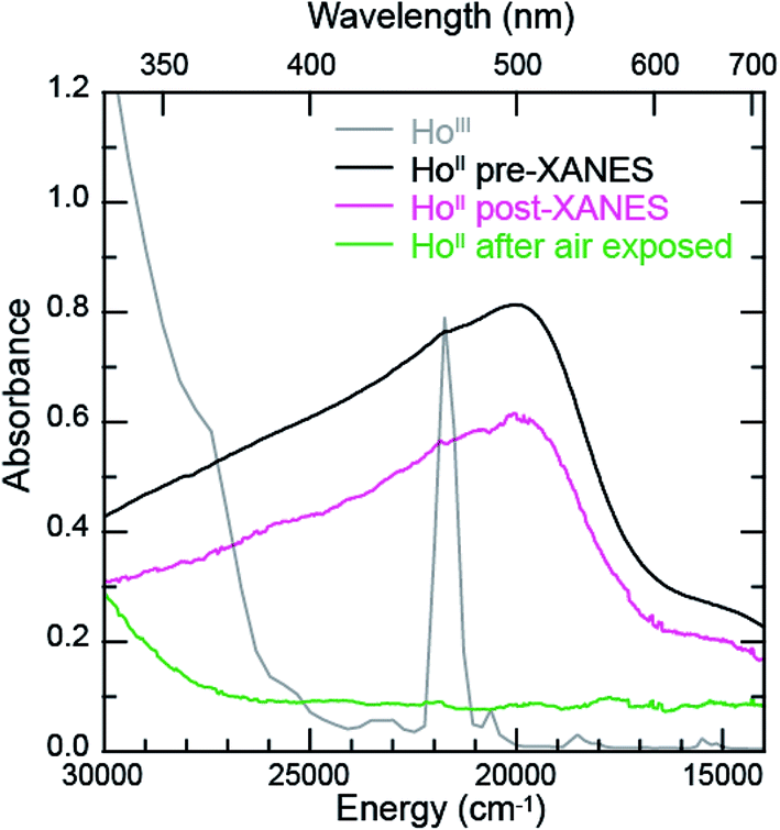 | ||
| Fig. 5 The background-subtracted UV-vis spectra obtained from HoIII(C5H4SiMe3)3 (grey trace) and [K(2.2.2-cryptand)][HoII(C5H4SiMe3)3]. Data from HoII(C5H4SiMe3)31− were collected (1st) before XANES analysis (black trace), (2nd) after XANES analysis (pink trace), and (3rd) after XANES analysis and exposure to air (green trace). | ||
Additional support that the Ho L3,2-edge XANES spectra obtained from HoII(C5H4SiMe3)31− was representative of the HoII organometallic was gleaned from a series of X-ray absorption decomposition experiments. For example, exposing HoII(C5H4SiMe3)31−, whose absorption peak is at 8075.6 eV, after XANES analysis to air caused the peak position to shift by 0.5 eV to 8076.0 eV, matching the 8076.1 eV peak in HoIII(C5H4SiMe3)3. Analysis of the second derivative of the LnIIversus LnIII data additionally revealed a spectral diagnostic for the unconventional LnII(C5H4SiMe3)31− (Fig. S4†) compounds. For example, all of the +3 LnIII(C5H4SiMe3)3 precursors contain a minimum in the second derivative approximately 2 eV lower in energy than the corresponding absorption peak. For Sm, Tm, and Yb, this feature is also persists after reduction to the LnII(C5H4SiMe3)31− complex. However, reduction to form unconventional divalents, Ln = Gd, Tb, Dy, Ho, Er, and Lu, caused the pre-edge features to disappear from the L3-edges XANES spectra. This observation is documented by the 2nd derivative plots shown in Fig. 6 for Ho(C5H4SiMe3)3x− (x = 1, 0) (see ESI† for the other L3-edge 2nd derivative spectra). We remind the reader that a minimum in the 2nd derivative indicates the presence of a peak in the XANES data. Fig. 6 shows the pre-edge peak at 8073.0 eV for HoIII(C5H4SiMe3)3. If the transition corresponds to a Ln 2p → 5d excitation, 5d-orbital population in LnII(C5H4SiMe3)31− would shift this feature higher in energy (owing to electron pairing energy) and make it more difficult to resolve. Consistent with this proposition, for Sm, Tm, and Yb analytes – which have 4fn 5d0 (for +3 metals) and 4fn+1 5d0 (for +2 metals) electronic configurations with empty 5d orbitals (for both +3 and +2 metals) – pre-edge features were observed in both the +3 and +2 spectra. Regardless of its identity, this pre-edge feature is unexpectedly sensitive to the amount of LnIII present in the LnII sample, as demonstrated by the Ho L3-edge XANES measurement made on a 1:1 mixture of HoIII(C5H4SiMe3)3 and HoII(C5H4SiMe3)31−, Fig. 6, which showed the pre-edge feature had a lower intensity than the pure HoIII starting material. The absence of the extra feature in the LnII(C5H4SiMe3)31− L3-edge XANES spectra provides a fortuitous alternative fingerprint for the LnII compounds with 4fn 5d1 electronic configurations. This is especially valuable when one considers that L3/L2 absorption peak area comparisons and branching ratio analyses were inconclusive (Table S1†), even for the Sm, Tm, and Yb analytes.
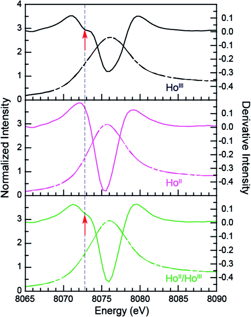 | ||
| Fig. 6 The background-subtracted and normalized Ho L3-edge XANES measurements obtained from HoIII(C5H4SiMe3)3 (black dashed trace), [K(2.2.2-cryptand)][HoII(C5H4SiMe3)3] (pink dashed trace) complexes, and a mixture of HoIII and HoII samples (green dashed trace). Second derivatives of the data are provides as solid traces. Note the pre-edge features (labeled with a red arrow) that are manifested as a minimum in the 2nd derivative. | ||
MII(C5H4SiMe3)31− K- and L3,2-edge XANES (M = Y, Lu)
The subtle rising edge energy shifts between LnII(C5H4SiMe3)31− and LnIII(C5H4SiMe3)3 are reminiscent of those accompanying changes in oxidation state for transition metals (K- and L-edges),17,18 not lanthanides. For example, changes in d-orbital occupancy only shift the K- and L-edges for transition metals by a few electron volts, which pales in comparison to the 7 eV shifts that accompany oxidation state changes in 4f-element chemistry. For example, the Y K-edge XANES data from YII(C5H4SiMe3)31− and YIII(C5H4SiMe3)3 show a 1.4 eV inflection point shift (Fig. 7, Table 1), which is consistent with the computational results generated using quantum chemical ab initio FEFF9.6 code based on the multiple scattering theory (see Fig. S3†).14 Hence, both experiment and theory indicate that YIII(C5H4SiMe3)3 has a 4d0 electronic configuration and YII(C5H4SiMe3)31− a 4d1 configuration. These Y K-edge XANES results agree with the previous analyses of YII(C5H4SiMe3)31− (UV-vis, EPR, structural metrics)1c and – to the best of our knowledge – represent the first Y K-edge XANES spectrum of a molecule containing YII. Also consider data from the Lu(C5H4SiMe3)3x− (x = 0, 1) pair. Lutetium in the +3 oxidation state has a full 4f-shell. Hence reduction of LuIII(C5H4SiMe3)3, with a 4f14 5d0 electron configuration, has to generate a 4f14 5d1 configuration in LuII(C5H4SiMe3)31−. Consistent with 5d-orbital occupation, the peak maxima difference between LuIII and LuII in the Lu L3,2-edge XANES was small, measured at 1.9 eV. | ||
| Fig. 7 The background-subtracted and normalized Y K-edge XANES measurements obtained from YIII(C5H4SiMe3)3 (black trace) and [K(2.2.2-cryptand)][YII(C5H4SiMe3)3] (pink dashed trace) complexes. | ||
Taken in the context of these Y(C5H4SiMe3)3x− and Lu(C5H4SiMe3)3x− (x = 0, 1) XANES measurements – alongside (1st) the experiments we conducted showing our XANES samples contained only marginal quantities of LnIII decomposition products, and (2nd) previously reported UV-vis data, structural metrics, previous computational results – the most plausible interpretations of these Ln L3-edge XANES data (Fig. 4) is that reduction of LnIII(C5H4SiMe3)3 to form an unconventional LnII(C5H4SiMe3)31− compound resulted in addition of an electron into a highly shielded 5d-orbital to generate a 4fn 5d1 electronic configuration, not 4fn+1 5d0. Although we anticipate that the spectra in Fig. 4 contain some LnIII contamination – in analogy to the SmII and TmII spectra in Fig. 1 to 3 – the computational results below provide even more support for the alternative electronic configuration.
Electronic structure calculations
To better understand the origin for the spectroscopic differences between LnIII(C5H4SiMe3)3versus LnII(C5H4SiMe3)31−, electronic structure calculations were conducted on a subset of Ln(C5H4SiMe3)3x− (Ln = Sm, Ho; x = 0, 1) complexes. This analysis compares SmII(C5H4SiMe3)31−, which is unambiguously +2, with HoII(C5H4SiMe3)31−, where the electronic configuration is ambiguous. Calculations for the LnII(C5H4SiMe3)31− compounds were restricted to just Sm and Ho, as a follow-on manuscript will compare theoretical results from the other LnII compounds with other +2 lanthanide and actinide species. Initially, DFT/PBE calculations were conducted to optimize the geometric structures of Ln(C5H4SiMe3)3x− (x = 1, 0), see Table 2 for a comparison of experimental and calculated distances and Table S2 (ESI†) for the coordinates. The computational results reveal a ground-state 4f5 5d0 electronic configuration (sextet state) for SmIII(C5H4SiMe3)3 and a 4f6 5d0 (septet state) configuration for SmII(C5H4SiMe3)31−. Because of the near-degeneracy of 4f-orbitals and the accompanying marginal participation in metal–ligand covalent bonding,11e varying 4f-occupations of the ground-state spin multiplicity has little effects on the geometric structures and spectra. The average 2.513 Å SmIII–Ccentroid distance is calculated to be 0.092 Å shorter than the 2.605 Å SmII–Ccentroid distance. This difference is consistent with the differences in SmIIIversus SmII ionic radii19 and changes in electrostatic interactions between SmIIIversus SmII with C5H4SiMe31− anions. These calculated distances compare well with experimental results8a and are within the typical error of 2% observed for GGA functionals.| Ho(C5H4SiMe3)3x− (x = 0, 1) | |||||||
|---|---|---|---|---|---|---|---|
| HoIII, 4f10 5d0 | HoII, 4f10 5d1 | HoII, 4f11 5d0 | Δ[HoII (4f10 5d1)–HoIII] | ||||
| PBE | Exp1b | PBE | Exp1b | PBE | PBE | Exp1b | |
| Ho–Cnt1 | 2.438 | 2.391 | 2.477 | 2.417 | 2.536 | 0.039 | 0.026 |
| Ho–Cnt2 | 2.441 | 2.393 | 2.461 | 2.420 | 2.509 | 0.020 | 0.027 |
| Ho–Cnt3 | 2.448 | 2.398 | 2.481 | 2.432 | 2.517 | 0.033 | 0.034 |
| Avg(Ho–Cnt) | 2.442 | 2.394 | 2.473 | 2.423 | 2.521 | 0.031 | 0.029 |
Consistent with previous hybrid DFT calculations that employed no less than 25% Hartree–Fock (HF) exchange,1b our calculations show the ground-state electronic structure of HoIII(C5H4SiMe3)3 is 4f10 5d0 (quintet state), whereas HoII(C5H4SiMe3)31− has a 4f10 5d1 configuration (sextet state). For example, calculations with the BHandHLYP functional show the 4f10 5d1 electronic configuration is 27 kcal mol−1 more stable than the alternative 4f11 5d0 configuration (quartet state). In contrast, calculations with functionals that included less HF exchange (PBE, BLYP, and B3LYP) incorrectly predict the alternative HoII 4f11 5d0 configuration as the ground-state (see details in Tables S2 and S3 of the ESI†).1b,1c,8a,8d That is to say, GGA and hybrid functionals with lower HF exchange percentages fail to give the correct HoII(C5H4SiMe3)31− spin state, which is likely attributable to the delocalization error.20,21 Many reports have described how increasing HF exchange improves the calculated energetics by DFT-based methods such as excitation energy,22 thermochemical kinetics,23 reaction barriers,24 and electron detachment energy.25 Consistently, our DFT/PBE calculated HoIII (4f10 5d0)–Ccentroid and HoII (4f10 5d1)–Ccentroid distances are in excellent agreement with experimental values (Table 2), while the HoII (4f11 5d0)–Ccentroid distances are longer than the experimental results by ∼0.1 Å.1b,1c These results provide confidence in assigning HoII as having a 4f10 5d1 electronic configuration. We refer the interested reader to the experimental section for details of the electronic structure calculation.
To better understand the unusual electronic configuration of HoII(C5H4SiMe3)31−, we found it instructive to interpret the DFT calculations using traditional molecular orbital descriptions derived from group theory considerations of M(C5H5)3 in C3h-symmetry. Hence, a qualitative MO level diagram for the C3h–HoII(C5H5)31− anion is provided in Fig. 8. As the molecular orbital interactions associated with LnIII(C5R5)3 (R = H or alkyl) have been the subject of numerous theoretical and spectroscopic studies,26 this discussion is confined to those orbitals most relevant to the Sm and Ho L3,2-edge XANES measurements. In contrast to previous theoretical results for MIII(C5H5)3 in D3h- or C3v-symmetry,26b,c,d,g,h,i,j we find it more appropriate to describe the MO-interaction using C3h-symmetry, as this designation more closely mimics data from the crystal structure of HoII(C5H4SiMe3)31−.
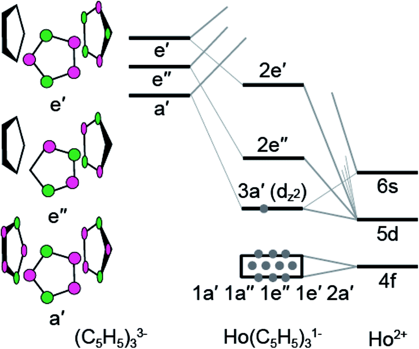 | ||
| Fig. 8 A qualitative molecular diagram showing molecular orbital interactions in C3h-symmetry for HoII(C5H5)31−. | ||
In the C3h-point group, symmetry allowed mixing between the metal 5d- and cyclopentadienyl π-orbitals – perpendicular to the ring planes – generates bonding interactions of a′, e′, and e′′ symmetries, which were σ- π- and δ-bonding with respect to the metal–cyclopentadienyl centroid axes, Fig. 8. Superimposed on this molecular orbital picture, and at lower energy, are Ln–(C5H5) σ-, π- and δ-bonding orbitals of a′, a′′, e′, and e′′ symmetries that originate from mixing between the 4f-orbitals and cyclopentadienyl π-orbitals. In general, the Ln(C5H4SiMe3)3x− (x = 0, 1) compounds exhibit little 4f- and cyclopentadienyl orbital mixing, such that the seven primarily 4f-orbitals span a narrow energy range. In contrast, substantial mixing occurs between the Ln 5d- and cyclopentadienyl π-orbitals, with the exception of the 5d-orbital of 3a′ symmetry (dz2). Consistent with previous reports,1b metal–cyclopentadienyl mixing is inhibited in this 3a′ orbital by poor spatial overlap. Hence, the 3a′ orbital is primarily composed of 5d- and 6s-character and best described as a non-bonding 5d-orbital. For SmIII(C5H4SiMe3)3 (4f5 5d0), SmII(C5H4SiMe3)31− (4f6 5d0), and HoIII(C5H4SiMe3)3 (4f10 5d0), the 3a′ orbital is empty. As testament, the BHandHLYP calculations at PBE optimized ground-state geometries show the Mulliken net spin densities27 to be almost exclusively distributed on 4f-orbitals (Table 3). Meanwhile, for the HoII(C5H4SiMe3)31− anion (4f10 5d1), significant 6s- and 5d-spin density distribution associated with the highest alpha spin occupied orbital indicates that the 3a′ orbital is singly occupied. A summary of the spin multiplicity results is provided in Table 3. The differences between the 4fn+1 5d0versus 4fn 5d1 electronic configurations of the LnII ions is observed to influence the metal–cyclopentadienyl bond distances and, as discussed below, is found to significantly impact the Ln L3-edge XANES spectrum.
| Compound | 2S + 1 | S2 | Spin | s | d | f | |
|---|---|---|---|---|---|---|---|
| SmIII(C5H4SiMe3)3 | 4f5 5d0 | 6 | 8.77 | 5.14 | 0.01 | 0.09 | 5.03 |
| SmII(C5H4SiMe3)31− | 4f6 5d0 | 7 | 12.01 | 6.04 | 0.01 | 0.06 | 5.96 |
| HoIII(C5H4SiMe3)3 | 4f10 5d0 | 5 | 6.00 | 4.04 | 0.00 | 0.04 | 3.97 |
| HoII(C5H4SiMe3)31− | 4f10 5d1 | 6 | 8.76 | 4.86 | 0.22 | 0.62 | 3.98 |
| HoII(C5H4SiMe3)31− | 4f11 5d0 | 4 | 3.76 | 3.02 | 0.00 | 0.01 | 3.01 |
To support the results from the ground-state DFT calculations, CASPT2/CASSCF calculations were performed on the ground-states and low excited-states of simplified Ln(C5H5)3x− (Ln = Sm, Ho; x = 0, 1) complexes. The DFT/PBE optimized geometries of Ln(C5H4SiMe3)3x− were used; however, to reduce the computational cost SiMe3 substituents were replaced with protons having C–H bond lengths of 1.088 Å. Two possibilities were investigated for HoII(C5H5)31−. The first was associated with the calculated structure of HoII(C5H4SiMe3)31− with a 4f10 5d1 ground-state electronic configuration. The second investigated HoII(C5H5)31− geometry was based on the calculated 4f11 5d0 HoII(C5H4SiMe3)31− structure. Although efforts were made to include all the seven 4f and five 5d orbitals into the active space, the converged CASSCF results for Sm(C5H5)3x− (x = 0, 1) showed that the five 5d-orbitals were not correlated and removed from the active space. Meanwhile for Ho(C5H5)3x− (x = 0, 1), only the 5dz2-orbital remained in the active space. Hence, the active space calculations were adjusted to include all seven 4f-orbitals for Sm(C5H5)3x− (x = 0, 1) and an additionally 5dz2-orbital for Ho(C5H5)3x− (x = 0, 1). The results generated a complete active space of 6-electrons with 7-orbitals for SmII(C5H5)31−, 5-electrons and 7-orbitals for SmIII(C5H5)3, 11-electrons and 8-orbitals for HoII(C5H5)31−, and 10-electrons with 8-orbitals for HoIII(C5H5)3.
Although subtle differences were observed, the ground-state electronic structure results from the CASPT2/CASSCF calculations are similar to those obtained by DFT (Table 4). The “core-like” and nearly degenerated 4f-orbitals resulted in different 4f-occupations with nearly the same energies. The CASPT2/CASSCF results show that SmIII(C5H5)3 has ground sextet state of 4f5 configurations and that SmII(C5H5)31− has ground septet state of 4f6 configuration, which are the same as DFT results. In the holmium case, HoIII(C5H5)3 has ground quintet state of 4f10 5d0. For HoII, both geometries showed a sextet with 4f10 5d1 configurations. These HoII and HoIII results were identical to the DFT calculations. Hence, in terms of evaluating ground-state electronic structures for the Ln(C5H5)3x− (x = 0, 1), the CASPT2/CASSCF results are in excellent agreement with the reported DFT results from Ln(C5H4SiMe3)3x− (x = 0, 1).
| Ground-state | Configurations |
|---|---|
| a 1a-7a are 4f orbitals, and 8a is 5d orbital. b Refer to the DFT/PBE calculated ground-state geometrics for HoII(4f105d1) and HoII(4f115d0), respectively, shown in Table 2. | |
| Sm II (C 5 H 5 ) 3 1− | |
| X7A | 100%(1a12a13a14a15a16a17a0) |
|
|
| Sm III (C 5 H 5 ) 3 | |
| X6A | 58%(1a12a13a14a15a16a07a0) + 41%(1a12a13a14a05a06a17a1) |
|
|
| Ho(C 5 H 5 ) 3 1− ; geometry from Ho II (C 5 H 4 SiMe 3 ) 3 1− (4f 10 5d 1 ) | |
| X6A | 71%(1a22a23a14a25a16a17a18a1) + 21%(1a22a13a24a15a26a17a18a1) + 7%(1a12a23a24a15a16a27a18a1) |
|
|
| Ho(C 5 H 5 ) 3 1− ; geometry from Ho II (C 5 H 4 SiMe 3 ) 3 1− (4f 11 5d 0 ) | |
| X6A | 70%(1a22a23a14a25a16a17a18a1) + 21%(1a22a13a24a15a26a17a18a1) + 7%(1a12a23a24a15a16a27a18a1) |
|
|
| Ho(C 5 H 5 ) 3 | |
| X5A | 65%(1a22a13a24a15a26a17a18a0) + 20%(1a22a23a14a25a16a17a18a0) + 5%(1a12a23a24a15a16a17a28a0) + 2%(1a22a13a14a15a26a27a18a0) + 1%(1a22a13a14a25a26a17a18a0) + 1%(1a22a13a24a15a16a17a28a0) + 1%(1a22a23a24a15a16a17a18a0) |
Spectral simulations
The open-shell Sm and Ho L3-edge XANES spectra from Ln(C5H4SiMe3)3x− (Ln = Sm, Ho; x = 0, 1), were calculated using the transition dipole moment approach based on the Kohn–Sham ground-state molecular orbitals. Using this method the core excitation energies were calculated as the energy differences between occupied and virtual orbitals. Previous studies have demonstrated that this approach provides a sound basis for interpreting the experimental XANES spectra.28 BHandHLYP simulated Ln L3-edge XANES spectra from Ln(C5H4SiMe3)3x− are compared with experimental results in Fig. 9 and 10. In these figures, the calculated spectra were shifted by a constant 241.49 eV (Sm) and 348.17 eV (Ho) to line up the LnIII(C5H4SiMe3)3 L3-edge peaks, which in turn accounts for omission of the atomic and extra-atomic relaxation associated with the core excitation, relativistic stabilization, and errors associated with the functionals.29,30 In the LnII cases, two options were explored, transitions that involved conventional electronic configurations, LnII 2p6…4fn+1 5d0 → LnII 2p5…4fn+1 5d1, and alternatives that involved 5d-orbital occupations, LnII 2p6…4fn 5d1 → LnII 2p5…4f1 5d2. The resulting near edge energies are summarized in Table 5 alongside analogous values acquired using PBE, BLYP, and B3LYP functionals.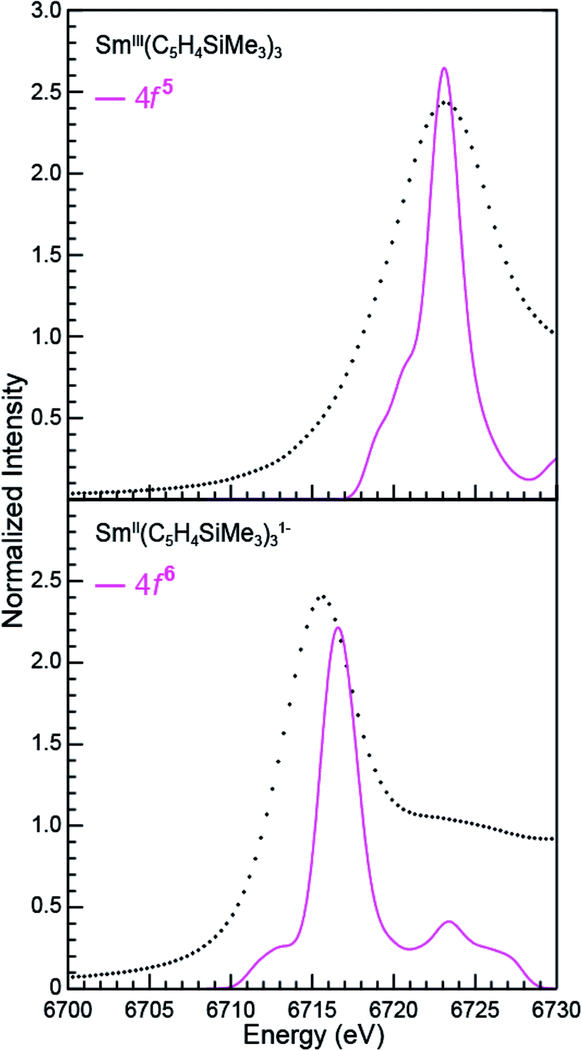 | ||
| Fig. 9 A comparison of the experimental (•) and transition dipole moment calculations (pink traces) for the Sm L3-edge XANES measurements obtained from SmIII(C5H4SiMe3)3 (top) and [K(2.2.2-cryptand)][SmII(C5H4SiMe3)3] (bottom). The calculated spectra were shifted by a constant 241.49 eV, which aligned the SmIII(C5H4SiMe3)3 experimental and calculated edge peak. | ||
 | ||
| Fig. 10 A comparison of the experimental (•) and transition dipole moment calculations (pink and green traces) for the Ho L3-edge XANES obtained from HoIII(C5H4SiMe3)3 (top) and [K(2.2.2-cryptand)][HoII(C5H4SiMe3)3] (bottom). The calculated spectra were shifted by a constant 348.17 eV, which aligned the HoIII(C5H4SiMe3)3 experimental and calculated edge peak. | ||
| PBE | BLYP | B3LYP | BHandHLYP | Exp. | ||
|---|---|---|---|---|---|---|
| SmIII(C5H4SiMe3)3 | 4f5 5d0 | 6873.4 | 6874.8 | 6910.7 | 6964.6 | 6723.2 |
| SmII(C5H4SiMe3)31− | 4f6 5d0 | 6870.8 | 6872.2 | 6906.1 | 6958.1 | 6715.6 |
| Δ[SmIII–SmII] | 2.6 | 2.6 | 4.6 | 6.5 | 7.6 | |
| HoIII(C5H4SiMe3)3 | 4f10 5d0 | 8325.6 | 8327.1 | 8366.6 | 8424.5 | 8076.1 |
| HoII(C5H4SiMe3)31− | 4f10 5d1 | 8325.8 | 8327.3 | 8366.2 | 8423.8 | 8075.6 |
| HoII(C5H4SiMe3)31− | 4f11 5d0 | 8322.6 | 8324.1 | 8361.1 | 8418.0 | — |
| Δ[HoIII–HoII (4f10 5d1)] | −0.2 | −0.2 | 0.4 | 0.7 | 0.5 | |
| Δ[HoIII–HoII (4f11 5d0)] | 3.0 | 3.0 | 5.5 | 6.5 | — |
The theoretical analyses reveal the primary contributions to the Ln L3-edge XANES spectra are electric dipole allowed excitations from Ln 2p-orbitals to unoccupied states that contain metal d-character. Of the functionals explored, the L3-edge energy differences calculated using BHandHLYP were in best agreement with the experiment. For example, in the Sm(C5H4SiMe3)3x− case, where the 4f- and 5d-orbital occupancies are well established, energy differences between the SmIII (4f5 5d0) and SmII (4f6 5d0) L3-edge positions are calculated to be 6.5 eV, which is in good agreement with the measured value of 7.6 eV. Results from the B3LYP calculations modestly agree with the experimental data, while larger deviations are observed using BLYP and PBE. The two GGA functionals, BLYP and PBE, without any HF exchange give the same L3-edge energy difference. This comparison (BHandHLYP, B3LYP, BLYP, and PBE) unambiguously shows the importance of Hartree–Fock (HF) exchange in computationally evaluating L3-edge XANES spectra. This result highlights the importance of high HF exchange in correctly capturing electron transition energies and is consistent with conclusions from previous theoretical studies.22
Calculations on Ho(C5H4SiMe3)3x− are similar to those from Sm(C5H4SiMe3)3x− in that the BHandHLYP provides the best agreement with the experimental data (Table 5), e.g. energy differences between the HoIII (4f10 5d0) and HoII (4f10 5d1) L3-edge peak maxima are calculated to be 0.7 eV and measured to be 0.5 eV. The Ho(C5H4SiMe3)3x− calculations differ in that they invoke the HoII low energy 4f10 5d1 ground-state electronic configuration. We note that calculations involving the higher energy 4f11 5d0 HoII electronic configuration grossly overestimate the HoIII/HoII L3-edge energy by 6.5 eV.
To better understand the how 4f- versus 5d-orbital occupancy influence Ln L3-XANES spectra, the ground-state 2p-orbital energies are plotted alongside the average 5d- and 6d-orbital energies in Fig. 11 for Ln(C5H4SiMe3)3x− (Ln = Sm, Ho; x = 0, 1). We remind the reader that the major contributors to the Ln(C5H4SiMe3)3x− L3-edge XANES spectra result from dipole allowed transitions between core 2p- and unoccupied d-orbitals. Upon reduction of LnIII to LnII, the 2p-, 5d-, and 6d-orbital energies increase. For both Sm and Ho, adding the electron into the 4f-shell, LnIII (4fn 5d0) + 1e1− → LnII (4fn+1 5d0), raises the Ln 2p- and 5d-/6d-orbital energies by 11.5–12.0 eV and 5.0–5.5 eV, respectively. These changes in orbital energies account for SmII(C5H4SiMe3)31− L3-edge excitation energy being ∼7 eV less than that of SmIII(C5H4SiMe3)3. Adding the electron into 5d-shell, LnIII (4fn 5d0) + 1e1− → LnII (4fn 5d1), also increases the Ln 2p- and 5d-/6d-orbital energies; however, to a lesser extent. Most notably for the 2p-orbitals. For example, the Ho 2p- and 5d/6d-average orbital energies increase by 4.6 eV and 3.9 eV, respectively. This modest energy shift decreases the L3-edge excitation energy for HoII(C5H4SiMe3)31− by <1 eV in comparison to HoIII(C5H4SiMe3)3. Overall, these results demonstrate that Ln 2p-electrons experienced stronger Coulomb repulsion from Ln 4f-electrons than higher lying 5d-electrons. We additionally correlate the magnitude of this repulsion with the radial distribution of the 4f- versus 5d-orbitals. Because the 4f-orbitals are closer to the nucleus,31 increased 4f-orbital occupancy destabilizes the core 2p-orbital energies to a large extent. Meanwhile, occupancy of the more diffuse 5d-orbitals has less impact on the 2p-orbital energies.
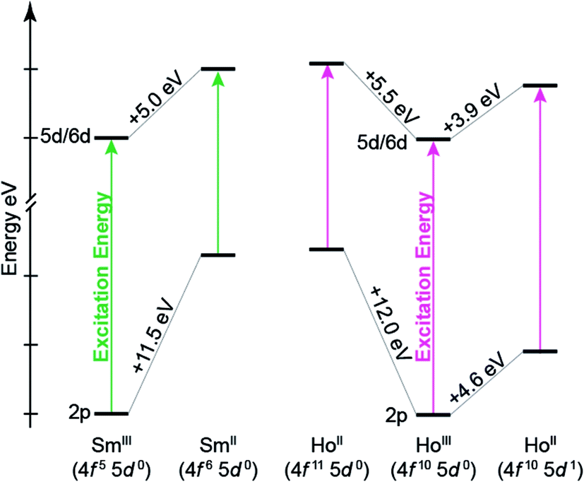 | ||
| Fig. 11 Quantitative comparison of ground-state 2p- and average 5d/6d-orbital energies from Ln(C5H4SiMe3)3x− (Ln = Sm, Ho; x = 0, 1) for a variety of electronic configurations. The solid arrow represents the excitation energy associated with the Ln L3-edge excitation. To plot both Sm and Ho on the energy scale, the energies associated with the LnIII 2p-orbitals were set to zero. | ||
Discussion
Herein we describe the use of XANES spectroscopy to characterize the electronic configurations of formally +2 lanthanide compounds of the general formula LnII(C5H4SiMe3)31−. Through comparisons with a carefully selected series of standards, including LnIII(C5H4SiMe3)3, our XANES results from SmII(C5H4SiMe3)31−, TmII(C5H4SiMe3)31− and YbII(C5H4SiMe3)31−demonstrate that these compounds contained LnII ions with 4f6 5d0 (SmII), 4f13 5d0 (TmII), and 4f14 5d0 (YbII) electronic configurations. These results are in agreement with previously acquired spectroscopic data, i.e. UV-vis, magnetic susceptibility, and the Ln–Ccentroid distances (which were ∼0.1 Å longer than the LnIII analogue). Consistent with previous studies,8a,8d the measurements highlight the utility of Ln L3,2-edge XANES spectroscopy in characterizing f-orbital occupancies from LnIII (4fn 5d0) and LnII (4fn+1 5d0) ions. For example, changes in 4f-electron occupancy shift the Ln peak maxima in the L3,2-edges by approximately 7 eV. The magnitude of these shifts is impressive in comparison to transition metal K- and L-edge XANES experiments,17,18 where changes in d-orbital occupancies are known to shift absorption edges by only a few eV.The Ln L-edge XANES studies from Ln(C5H4SiMe3)3x− (Ln = Pr, Nd, Gd, Tb, Dy, Ho, and Er; x = 0, 1) show much smaller shifts in rising-edge energies than the samarium, thulium, and ytterbium analogues. For example, the peak maxima differences between LnIII(C5H4SiMe3)3 and LnII(C5H4SiMe3)31− range from only 0.2 to 1.0 eV (Table 1). These values are substantially less than the 7–8 eV change expected for an increase in 4f-orbital occupancy, i.e. LnIII (4fn 5d0) + e1− → LnII (4fn+1 5d0). Instead, the 0.2 to 1.0 eV shifts are reminiscent of the those accompanying the reduction of YIII(C5H4SiMe3)3 (4d0) to YII(C5H4SiMe3)31− (4d1) and LuIII(C5H4SiMe3)3 (4f14 5d0) to LuII(C5H4SiMe3)31− (4f14 5d1). In these yttrium and lutetium scenarios, the increase in d-orbital occupancy shifts the peak maximum by only ~1 eV (inflection point change of 1.4 eV) and 1.9 eV, respectively. These shifts provide strong evidence that the yttrium ion in YII(C5H4SiMe3)31− is best described as +2 with a 4d1 electronic configuration and that the lutetium ion in LuII(C5H4SiMe3)31− is +2 with a 4f14 5d1. Given that shifts from Ln(C5H4SiMe3)3x− (Ln = Pr, Nd, Gd, Tb, Dy, Ho, and Er; x = 0, 1) were also small, we initially questioned the possibility that reduction of LnIII(C5H4SiMe3)3 (4fn 5d0) generated a lanthanide ion with a 4fn 5d1 electronic configuration, instead of the more typical 4fn+1 5d0 configuration.
To better understand the Ln L3-edge XANES spectra from Ln(C5H4SiMe3)3x− (x = 0, 1), DFT calculations were conducted on the Sm(C5H4SiMe3)3x− and Ho(C5H4SiMe3)3x− analytes. Consistent with previous reports, the ground-state DFT calculations show the electronic configurations for SmIII(C5H4SiMe3)3, SmII(C5H4SiMe3)31−, and HoIII(C5H4SiMe3)3 are SmIII 4f5 5d0, SmII 4f6 5d0, and HoIII 4f10 5d0, respectively. In contrast for HoII(C5H4SiMe3)31−, the calculations indicate that the ground-state electronic configuration is 4f10 5d1, with the non-bonding 5dz2-orbital of a′-symmetry being singly occupied. CASPT2/CASSCF calculations on the simplified models, Ln(C5H5)3x− (Ln = Sm, Ho; x = 0, 1), were completely consistent with the assignments of the DFT calculations. As such the Ln L3-edge XANES spectra were simulated using transition dipole moment calculations for a variety of electronic configurations, spanning LnIII 4fn 5d0, LnII 4fn+1 5d0, and LnII 4fn 5d1. For both Sm and Ho, the calculations suggest that reducing LnIII (4fn 5d0) by adding an electron in the 4f-manifold to generate LnII (4fn+1 5d0) appreciably shifts the Ln L3-edge by approximately 7 eV. In contrast, reducing LnIII (4fn 5d0) by adding an electron into the 5d-manifold to generate LnII (4fn 5d1) slightly shifts the Ln L3-edge to lower energy (on the order of ∼1 eV).
Concluding remarks
Our results indicate that the differences in Ln(C5H4SiMe3)3x− (Ln = Sm, Ho; x = 0, 1) excitation energies stem from electron repulsion between 2p- and either 5d- or 4f-electrons (Fig. 11). For example, increases in Ln 4f-orbital occupation significantly destabilize the core 2p-orbital energy levels, which decrease the Ln L3-edge excitation energy by ∼7–8 eV. In contrast, increased occupancy for the more diffuse 5d-orbitals has marginal impact on core 2p-energy levels and the Ln L3-edge excitation energy (0.2–1.9 eV). One might describe the 4f10 5d1 electron configuration in HoII(C5H4SiMe3)31− as mimicking the 4f10 electronic configuration in HoIII(C5H4SiMe3)3, with the extra electron ‘hidden’ in a highly shielded 5d-orbital. We anticipate that this interpretation is quite general and will be used to explain the similar LnII/LnIII peak maxima shifts and LnII/LnIII–Ccentroid bond distances in the other Ln(C5H4SiMe3)3x− (Ln = Pr, Nd, Gd, Tb, Dy, Er, and Lu; x = 0, 1) compounds. Hence, our current computational and spectroscopic efforts are focused on evaluating recently reported compounds that contain formally lanthanide(II) and actinide(II) ions.Among the numerous examples where ligand environments with C3-symmetry have been exploited to advance transition metal and f-element chemistry,32 our results highlight another extraordinary property associated with a C3-ligand framework. For example, we identified that the tris-cyclopentadienyl coordination environment provides a mechanism for stabilizing LnII 4fn 5d1 electronic configurations through the accessibility of a low-lying 5d-orbital of a′ symmetry. The results additionally suggest an electronic structure break between TmII(C5H4SiMe3)31− and DyII(C5H4SiMe3)31−. It appears that 4fn+1 5d0 electronic configurations are most stable when the reduction potentials for the lanthanide ions in LnII(C5H4SiMe3)31− are less than or equal to that of TmII(C5H4SiMe3)31−. Meanwhile, those with reduction potentials greater than or equal to DyII(C5H4SiMe3)31− are best described as 4fn 5d1. While the generality of this interpretation has yet to be determined, we anticipate – based on previous studies on LnX2 (X = halide) – that the electronic structure breaking point is quite dynamic and can shift to higher reduction potentials, i.e. those of DyII and NdII, depending in the ligand environment. Our current efforts are focused on identifying the implications of these results on lanthanide reactivity.
Experimental
Sample preparation
The analytes were synthesized at the University of California in Irvine CA with rigorous exclusion of air and moisture.1c,8a The LnIII(C5H4SiMe3)3,33 LnII(C5H4SiMe3)31−,1,8a SmII(C5Me5)2(THF)2,34 SmIII[N(SiMe3)2]3,35 SmII[N(SiMe3)2]2(THF)2,36 TmIII2(THF)2,37 and TmIIII3(THF)3.5 (ref. 38) were prepared as previously described. Analytes were sealed in ampoules and transported in a cooler filled with dry ice to the Stanford Synchrotron Radiation Lightsource (SSRL) where they were stored at −80 °C. Three hours prior to analysis by XAFS, the lanthanide samples were transferred into an argon filled glovebox. The samples were kept cold by preparing them on an aluminum block, which had been plumbed to accommodate flowing helium gas cooled from a dry ice/ethanol bath. Note, all equipment (including the holder, spatulas, wrenches, boron nitride, etc.) were cooled on the block prior to sample preparation. Samples were diluted with boron nitride, which had been dried at elevated temperature (200 °C) under vacuum (10−3 Torr) for 48 hours. A mixture of the analyte and BN were weighed out, such that the edge jump for the absorbing atom was calculated to be at ∼1 absorption length in transmission (between 8 to 30 mg of sample and ∼50 mg of BN). Samples were ground using a Wig-L-Bug®, a Teflon bead, and a polycarbonate capsule. The finely ground powders were pressed as a pellet into a slotted aluminum sample holder. These precautions were taken to minimize self-absorption. The holder was equipped with Kapton windows (1 mil), one was fixed with super glue and the other was Kapton tape. For Pr, Nd, Sm, Gd, Tb, Dy, Y, Ho, Er, Tm, Yb and Lu analytes, the holder was brought out of the glovebox, immediately submerged in liquid nitrogen for transportation to the beam line, and loaded into the cryostat. The cryostat was immediately evacuated and attached to the beamline 11-2 XAFS rail and cooled with either liquid nitrogen or liquid helium.Data acquisition
The cryostat was attached to the beamline 11-2 XAFS rail (SSRL), which was equipped with three ionization chambers through which nitrogen gas was continually flowed. One chamber (10 cm) was positioned before the cryostat to monitor the incident radiation (I0). The second chamber (30 cm) was positioned after the cryostat so that sample transmission (I1) could be evaluated against I0 and so that the absorption coefficient (μ) could be calculated as ln(I0/I1). The third chamber (I2; 30 cm) was positioned downstream from I1 so that the XANES of a calibration foil could be measured against I1. A potential of 1600 V were applied in series to the ionization chambers.Samples were calibrated to the energy of the first inflection point of a calibration foil, whose spectrum was measured in situ from the sample using the transmitted portion of the beam. The measurements were calibrated as follows. The Y K-edges were calibrated to the Y K-edge (17038.4 eV) of an yttrium foil. The Lu L3-edge to the Cu K-edge of a copper foil at 8979 eV. The Er and Yb L3-edges to the Ni K-edge of a nickel foil at 8333 eV. The Tm L3-edges were calibrated to the Ho L3-edge at 8070.1 eV. The Dy L3-edge was calibrated to the Dy L3-edge of a dysprosium foil at 7790.0 eV. The Ho L3-edges to the Co K-edge of a cobalt foil at 7709 eV. Sm, Gd, and Tb L-edges to the Fe K-edge of an iron foil at 7111 eV. The Pr, and Nd L-edges to the Cr K-edge of a chromium foil at 5989 eV.
The X-ray absorption near edge spectra (XANES) were measured at the SSRL, under dedicated operating conditions (3.0 GeV, 5%, 500 mA using continuous top-off injections) on end station 11-2. This beamline, which was equipped with a 26-pole, 2.0 tesla wiggler, utilized a liquid nitrogen-cooled double-crystal Si[220] monochromator and employed collimating and focusing mirrors. A single energy was selected from the white beam with a liquid-N2-cooled double-crystal monochromator utilizing Si[220] (φ = 0) crystals. Harmonic rejection was achieved by detuning the second crystal of the monochromator by 50% at ∼600 eV above the absorbing edge. The vertical slit sizes were 1 mm and the beam was unfocused.
Data analysis
Data manipulations and analyses were conducted as previously described.39 Energy calibrations were conducted externally using the first inflection point of the rising edge of the calibration spectrum. Data were analyzed by fitting a line to the pre-edge region, which was subsequently subtracted from the experimental data to eliminate the background of the spectrum. The data were normalized by fitting a first-order polynomial to the post-edge region of the spectrum and setting the edge jump at to an intensity of 1.0.UV-visible spectroscopy
Prior to transporting the HoII(C5H4SiMe3)31− samples to the synchrotron, the compound was characterized by UV-vis, as previously reported.8 The sample was first prepared for XANES analysis in an argon-filled glovebox by finely grinding HoII(C5H4SiMe3)31− (19.4 mg) with cold anhydrous boron nitride, BN (60.6 mg) for 2 min in polystyrene canisters with plexiglass pestles using a Wig-L-Bug® grinder to obtain a homogeneous fine powder. The sample was loaded within a slotted aluminum holder, whose slot dimensions were 5 × 20 × 1 mm. The holder was equipped with Kapton tape windows (1 mL). This holder was nested within an additional holder, also equipped with Kapton windows (1 mL) that were sealed with indium wire gaskets. This holder is well established as providing robust exclusion of air and moisture. The sample holder was placed on the rail at SSRL's beam line 11-2 and the Ho L3-edge spectrum obtained in transition mode at room temperature. After data collection the holder was returned to the glovebox and disassembled. The HoII(C5H4SiMe3)31− and BN mixture was transferred to a Teflon sealable quartz cuvette with THF (dried over Na/K alloy and benzophenone). The sample was again removed from the glovebox and analyzed using a CARY 50 spectrometer. The UV-vis data were background-subtracted. Owing to the suspended BN, a constant 1.15 absorption value was subsequently subtracted to set the background to zero.Density functional calculations
Ground-state electronic structure calculations were performed on the Ln(C5H4SiMe3)3x− (Ln = Sm, Ho; x = 0, 1) using the generalized gradient approximation (GGA) with the PBE exchange–correlation functional40 as implemented in the Amsterdam Density Functional (ADF 2014.11).41–43 For geometry optimization, the Slater basis sets with the quality of triple-ζ plus one polarization functions (TZP)44 were used, with the frozen core approximation applied to the inner shells [1s2–4d10] for Sm and Ho, [1s2] for C, [1s2–2p6] for Si. All electron TZ2P basis sets were used for spectroscopic simulation by employing the PBE,40 BLYP,45,46 B3LYP,45,46 and BHandHLYP47,48 functionals. The latter three functionals combine the LYP46 GGA for correlation with three different approximations for exchange, i.e., Becke's GGA (B)45 for exchange, the Becke's three-parameter (B3)47 hybrid functional including 20% HF exact exchange, and the half-and-half hybrid containing 50% HF exact exchange.48 The B3LYP and BHandHLYP functionals were chosen because they give good performance in excitation energy of charge-transfer states and were commonly used.22a,49,50 The BLYP was employed together with B3LYP and BHandHLYP to study the impact of the percentage of HF exchange on the excitation energy and spectral shape. The scalar relativistic (SR) effects were taken into account by the zero-order regular approximation (ZORA).51 Geometries were fully optimized without symmetry at the SR-ZORA level with the gradient convergence of 10−5, and frequency calculations were carried out to verify the local minimum on the potential energy surface. In the ground-state electronic structure calculations for Ln(C5H4SiMe3)3x− (Ln = Sm, Ho; x = 0, 1), the high-spin multiplicity was used for each electron configuration. Specifically, SmIII (4f5 5d0) had a ground sextet state, and SmII (4f6 5d0) had a ground septet state; HoIII (4f10 5d0) has ground quintet state, and HoII (4f10 5d1) had a ground sextet state, and HoII (4f11 5d0) had ground quartet state (Table 3).DFT-simulation of Ln L3-edge XANES spectra
The L3-edge XANES spectra from Ln(C5H4SiMe3)3x− (Ln = Sm, Ho; x = 0, 1) were simulated as the Kohn–Sham orbital energy differences, i.e., the energy difference between an occupied orbital and a virtual orbital of the ground-state. For a specific core excitation, the oscillator strength was calculated from the transition dipole approximation between this occupied orbital and the virtual orbital. The core electron excitation was calculated originating from Ln 2p dominated MOs to virtual MOs at the DFT/PBE optimized ground-state geometry. All other excitations from orbitals between the Ln 2p and HOMOs were excluded by restricting the energy range of the occupied orbitals involved in the excitations, so that only excitations from Ln 2p core levels to virtual MOs were allowed. The relaxation due to the core hole was assumed constant. All the calculated transition intensities were evenly broadened with a Gaussian function of full-width at half-maximum of 1.7 eV (i.e., peak width) to emulate the experimental spectra.FEFF spectral simulations
The Ln(C5H4SiMe3)3x− (Ln = Sm and Tm; x = 0, 1) Sm and Tm L3-edge and Y(C5H4SiMe3)3x− (x = 0, 1) Y K-edge XANES spectra and the angular momentum projected density of states were calculated with the FEFF9.6 ab initio quantum chemical code based on the multiple scattering theory (see ESI†).14 The potentials of free atoms were calculated with a relativistic Dirac–Fock atom code part of FEFF9.6. The scattering potentials were calculated self-consistently by overlapping the free atomic densities in the muffin tin approximation within a cluster of 334 atoms (SCF card; UNFREEZF card was not included). The energy dependent exchange Hedin–Lundquist potential was used for the fine structure and the atomic background (EXCHANGE card). The full multiple scattering XANES spectra were calculated for an atomic cluster of 334 atoms centered on the absorbing Sm/Tm/Y atom (FMS and XANES cards). Best agreement between calculation and experiment was found by applying “COREHOLE FSR” option to screen the 2p3/2 (Sm/Tm) or 1s (Y) core-holes. The FOLP card (FOLP 1 1.07) was used for calculating the Sm spectra, as the overlap of the muffin tin radii was reported to be too large by the program. This value was chosen as it was found for the calculations of the Tm and Y spectra. We have obtained comparable results (not shown here) for Tm by including the f valence states in the self-consistent calculations of the scattering potentials (UNFREEZF card).CASPT2/CASSCF calculations
Using the complete-active-space multi-configuration approach with second-order perturbation theoretical correction (CASPT2)52,53 implemented in Molpro 2015.1 program, ab initio WFT calculations were performed.54,55 To reduce the computational cost, CASPT2/CASSCF calculations were carried out on the ground-states and low excited-states of the simplified Ln(C5H5)3x− (Ln = Sm, Ho; x = 0, 1) complexes. The DFT/PBE optimized geometries of Ln(C5H4SiMe3)3x− were used in the calculations. Here the original SiMe3 substituents, ancillary groups, were replaced with protons having C–H bond lengths of 1.088 Å. For Ho(C5H5)31−, two geometries derived from HoII (4f11 5d0) and HoII (4f10 5d1) were used. We applied the cc-pVDZ basis sets for H and C,56 Stuttgart energy-consistent relativistic pseudopotentials ECP28MWB,57,58 and the corresponding ECP28MWB-SEG basis for Sm and Ho. Although attempts to include all the seven 4f- and five 5d-orbitals into active space were made, the converged CASSCF results showed that for Sm(C5H5)3x− (x = 0, 1) the five 5d-orbitals are not correlated and were removed out of active space. In contrast for Ho(C5H5)3x− (x = 0, 1), only the 5dz2-orbital remained in the active space. Therefore, the active space was adjusted to include all the 4f-orbitals for Sm(C5H5)3x− (x = 0, 1) and additionally the 5dz2 – character orbital for Ho(C5H5)3x− (x = 0, 1). In the CASPT2 calculations, the ionization-potential/electron-affinity corrected zeroth-order Hamiltonian was used with an IPEA shift of 0.25 a.u.59 The 1s-core orbitals of the C atoms, and 4s-, 4p-, 4d-orbitals of the Sm and Ho atoms were kept frozen in the CASPT2 calculations.Acknowledgements
The spectroscopic and computational work was supported under the Heavy Element Chemistry Program at LANL by the Division of Chemical Sciences, Geosciences, and Biosciences, Office of Basic Energy Sciences, U.S. Department of Energy (Su, Batista, Kozimor, Wagner, Yang). Los Alamos National Laboratory is operated by Los Alamos National Security, LLC, for the National Nuclear Security Administration of U.S. Department of Energy (contract DE-AC52-06NA25396). Synthetic work was done under Grant CHE-1565776 from the U.S. National Science Foundation at UCI by (Fieser, Evans, Ryan, Woen). Portions of this research were carried out at the Stanford Synchrotron Radiation Lightsource, a Directorate of SLAC National Accelerator Laboratory and an Office of Science User Facility operated for the U.S. Department of Energy Office of Science by Stanford University. The calculations in this research were performed using the Molecular Science Computing (MSC) Facilities in the William R. Wiley Environmental Molecular Sciences Laboratory (EMSL), a national scientific user facility sponsored by the U.S. DOE BER and located at Pacific Northwest National Laboratory. We additionally acknowledge the Helmholtz Association of German Research Center for the VH-NG-734 grant (Vitova). Portions of this work were supported at LANL by the Glenn T. Seaborg Institute Postdoctoral Fellowship (Ferrier, Su, Olson, Stein). We additionally thank the Marie Curie postdoctoral fellowship for support (Cary).References
-
(a) M. R. MacDonald, J. W. Ziller and W. J. Evans, J. Am. Chem. Soc., 2011, 133, 15914 CrossRef CAS PubMed
; (b) M. R. MacDonald, J. E. Bates, M. E. Fieser, J. W. Ziller, F. Furche and W. J. Evans, J. Am. Chem. Soc., 2012, 134, 8420 CrossRef CAS PubMed
- G. Parkin, J. Chem. Educ., 2006, 83, 791 CrossRef CAS
- P. Karen, Angew. Chem., Int. Ed., 2015, 54, 4716 CrossRef CAS PubMed
- L. R. Morss, Chem. Rev., 1976, 76, 827 CrossRef CAS
-
(a)
G. Meyer and M. S. Wickleder, Handbook on the Physics and Chemistry of Rare Earths, Elsevier Science B. V., Amsterdam, 2000, vol. 28 Search PubMed
- P. B. Hitchcock, M. F. Lappert, L. Maron and A. V. Protchenko, Angew. Chem., Int. Ed., 2008, 47, 1488 CrossRef CAS PubMed
-
(a) W. J. Evans, N. T. Allen and J. W. Ziller, J. Am. Chem. Soc., 2000, 122, 11749 CrossRef CAS
-
(a) M. E. Fieser, M. R. MacDonald, B. T. Krull, J. E. Bates, J. W. Ziller, F. Furche and W. J. Evans, J. Am. Chem. Soc., 2015, 137, 369 CrossRef CAS PubMed
- K. Binnemans and C. Görller-Walrand, Chem. Phys. Lett., 1995, 235, 163 CrossRef CAS
-
(a) A. V. Soldatov, Y. V. Sukhetsky and A. Bianconi, Nucl. Instrum. Methods Phys. Res., Sect. B, 1991, 308, 246 CrossRef
-
(a) S. G. Minasian, J. M. Keith, E. R. Batista, K. S. Boland, C. N. Christensen, D. L. Clark, S. D. Conradson, S. A. Kozimor, R. L. Martin, D. E. Schwarz, D. K. Shuh, G. L. Wagner, M. P. Wilkerson, L. E. Wolfsberg and P. Yang, J. Am. Chem. Soc., 2012, 134, 5586 CrossRef CAS PubMed
-
(a) S. Harder, D. Naglav, C. Ruspic, C. Wickleder, M. Adlung, W. Hermes, M. Eul, R. Pottengen, D. B. Rego, F. Poineau, K. R. Czerwinski, R. H. Herber and I. Nowik, Chem.–Eur. J., 2013, 19, 12272 CrossRef CAS PubMed
-
(a) B. Qi, I. Perez, P. H. Ansari, F. Lu and M. Croft, Phys. Rev. B: Condens. Matter Mater. Phys., 1987, 36, 2972 CrossRef CAS
- J. J. Rehr, J. J. Kas, F. D. Vila, M. P. Prange and K. Jorissen, Phys. Chem. Chem. Phys., 2010, 12, 5503 RSC
-
(a) M. R. Antonio, L. Soderholm and I. Song, J. Appl. Electrochem., 1997, 27, 784 CrossRef CAS
- N. B. Mikheev, L. N. Auerman, I. A. Rumer, A. N. Kamenskaya and M. Kazakevich, Russ. Chem. Rev., 1992, 61, 990 CrossRef
-
(a) S. Yoshida, T. Tanak, T. Hanada, T. Huraiwa, H. Kanai and T. Funabiki, Catal. Lett., 1992, 12, 277 CrossRef CAS
-
(a) M. M. Grush, J. Chen, T. L. Stemmler, S. J. George, C. Y. Ralston, R. T. Stibrany, A. Gelasco, G. Christou, S. M. Gorun, J. E. Penner-Hahn and S. P. Cramer, J. Am. Chem. Soc., 1996, 118, 65 CrossRef CAS
- R. D. Shannon, Acta Crystallogr., 1976, A32, 751 CrossRef CAS
- A. J. Cohen, P. Mori-Sanchez and W. Yang, Chem. Rev., 2012, 112, 289 CrossRef CAS PubMed
- V. B. Oyeyemi, J. A. Keith, M. Pavone and E. A. Carter, J. Phys. Chem. Lett., 2012, 3, 289 CrossRef CAS PubMed
-
(a) R. J. Magyar and S. J. Tretiak, J. Chem. Theory Comput., 2007, 3, 976 CrossRef CAS PubMed
- Y. Zhao and D. G. Truhlar, Theor. Chem. Acc., 2008, 120, 215 CrossRef CAS
-
(a) J. L. Durant, Chem. Phys. Lett., 1996, 256, 595 CrossRef CAS
- P. D. Dau, J. Su, H.-T. Liu, D.-L. Huang, J. Li and L.-S. Wang, J. Chem. Phys., 2012, 137, 064315 CrossRef PubMed
-
(a) J. W. Lauher and R. J. Hoffmann, J. Am. Chem. Soc., 1976, 98, 1729 CrossRef CAS
- R. S. Mulliken, J. Chem. Phys., 1955, 23, 1833 CrossRef CAS
-
(a) M. Coreno, M. de Simone, J. C. Green, N. Kaltsoyannis, R. Coates, C. Hunston, N. Narband and A. Sella, Dalton Trans., 2014, 43, 5134 RSC
-
R. L. Martin and D. A. Shirley, Many electron theory of electron emission, in Electron Spectroscopy: Theory, Techniques and Applications, ed. C. R. Brundle and A. D. Baker, Academic Press, London, 1977, vol. 1, pp. 75−117 Search PubMed
- M. Segala and D. P. Chong, J. Electron Spectrosc. Relat. Phenom., 2010, 182, 141 CrossRef CAS
-
T. Saue and L. Visscher, Relativistic All-Electron Approaches to the Study of f Element Chemistry. in Computational Methods in Lanthanide and Actinide Chemistry, ed. M. Dolg, Wiley, Chichester, UK, 2015, ch. 3, pp. 55–87 Search PubMed
-
(a) M. Keyes and W. B. Tolman, Adv. Catal. Processes, 1997, 2, 189 CAS
-
(a) S. D. Stults, R. A. Andersen and A. Zalkin, Organometallics, 1990, 9, 115 CrossRef CAS
- W. J. Evans, J. W. Grate, H. W. Choi, I. Bloom, W. E. Hunter and J. L. Atwood, J. Am. Chem. Soc., 1985, 107, 941 CrossRef CAS
- F. T. Edelmann, Synth. Methods Organomet. Inorg. Chem., 1997, 6, 37 Search PubMed
- W. J. Evans, D. K. Drummond, H. Zhang and J. L. Atwood, Inorg. Chem., 1988, 27, 575 CrossRef CAS
- W. J. Evans and N. T. Allen, J. Am. Chem. Soc., 2000, 122, 2118 CrossRef CAS
- K. Izod, S. T. Liddle and W. Clegg, Inorg. Chem., 2004, 43, 214 CrossRef CAS PubMed
-
S. Calvin, XAFS for everyone, CRC Press, 2013 Search PubMed
- J. P. Perdew, K. Burke and M. Ernzerhof, Phys. Rev. Lett., 1996, 77, 3865 CrossRef CAS PubMed
- ADF 2014.11, http://www.scm.com.
- C. F. Guerra, J. G. Snijders, G. te Velde and E. J. Baerends, Theor. Chem. Acc., 1998, 99, 391 CAS
- G. T. Velde, F. M. Bickelhaupt, E. J. Baerends, C. F. Guerra, S. J. A. van Gisbergen, J. G. Snijders and T. J. Ziegler, Comput. Chem., 2001, 22, 931 CrossRef
- E. van Lenthe and E. J. Baerends, Comput. Chem., 2003, 24, 1142 CrossRef CAS PubMed
- A. D. Becke, Phys. Rev. A, 1988, 38, 3098 CrossRef CAS
- C. Lee, W. Yang and R. G. Parr, Phys. Rev. B: Condens. Matter Mater. Phys., 1988, 37, 785 CrossRef CAS
- A. D. Becke, J. Chem. Phys., 1993, 98, 5648 CrossRef CAS
- A. D. Becke, J. Chem. Phys., 1993, 98, 1372 CrossRef CAS
- E. Ronca, C. Angeli, L. Belpassi, F. De Angelis, F. Tarantelli and M. Pastore, J. Chem. Theory Comput., 2014, 10, 4014 CrossRef CAS PubMed
- P. J. Lestrange, P. D. Nguyen and X. Li, J. Chem. Theory Comput., 2015, 11, 2994 CrossRef CAS PubMed
- E. van Lenthe, E. J. Baerends and J. G. Snijders, J. Chem. Phys., 1993, 99, 4597 CrossRef CAS
- H. J. Werner, Mol. Phys., 1996, 89, 645 CrossRef CAS
- P. Celani and H. J. Werner, J. Chem. Phys., 2000, 112, 5546 CrossRef CAS
- H. J. Werner, P. J. Knowles, G. Knizia, F. R. Manby and M. Schütz, Molpro: a general-purpose quantum chemistry program package, Wiley Interdiscip. Rev.: Comput. Mol. Sci., 2012, 2, 242 CrossRef CAS
-
H.-J. Werner, P. J. Knowles, G. Knizia, F. R. Manby and M. Schütz, and others, MOLPRO, version 2015.1, a package of ab initio programs, see http://www.molpro.net Search PubMed
- T. H. Dunning Jr, J. Chem. Phys., 1989, 90, 1007 CrossRef
- M. Dolg, H. Stoll and H. Preuss, J. Chem. Phys., 1989, 1730, 90 Search PubMed
- X. Cao and M. Dolg, J. Mol. Struct.: THEOCHEM, 2002, 581, 139 CrossRef CAS
- G. Ghigo, B. O. Roos and P. A. Malmqvist, Chem. Phys. Lett., 2004, 396, 142 CrossRef CAS
Footnotes |
| † Electronic supplementary information (ESI) available: The results from quantum chemical ab initio FEFF9.6 code calculations for LnII L3-edges from Ln(C5H4SiMe3)3x− (Ln = Sm, Tm, Y; x = 0, 1) and second derivative analysis of the lanthanides are in the ESI.† Our branching ratio analysis, the PBE//TZP optimized ground-state geometrical xyz coordinates and XC//TZ2P (XC = PBE, BLYP, B3LYP, BHandHLYP), single-point calculated total bonding energies of Ln(C5H4SiMe3)31−/0 (Ln = Sm, Ho), and relative single-point energy difference in kcal mol−1 between 4f10 5d1 and 4f11 5d0 in HoII(C5H4SiMe3)31− from different functional results at the PBE//TZP optimized ground-state geometries are also included. See DOI: 10.1039/c7sc00825b |
| ‡ M. E. Fieser, M. G. Ferrier, J. Su contributed equally to this work. |
| This journal is © The Royal Society of Chemistry 2017 |