 Open Access Article
Creative Commons Attribution 3.0 Unported Licence
Adsorption and molecular siting of CO2, water, and other gases in the superhydrophobic, flexible pores of FMOF-1 from experiment and simulation†
Peyman Z.
Moghadam‡
 a,
Joshua F.
Ivy‡
b,
Ravi K.
Arvapally‡
 b,
Antonio M.
dos Santos
c,
John C.
Pearson
bf,
Li
Zhang
ad,
Emmanouil
Tylianakis
e,
Pritha
Ghosh
a,
Iain W. H.
Oswald
b,
Ushasree
Kaipa
b,
Xiaoping
Wang
b,
Antonio M.
dos Santos
c,
John C.
Pearson
bf,
Li
Zhang
ad,
Emmanouil
Tylianakis
e,
Pritha
Ghosh
a,
Iain W. H.
Oswald
b,
Ushasree
Kaipa
b,
Xiaoping
Wang
 *c,
Angela K.
Wilson
*bf,
Randall Q.
Snurr
 *a and
Mohammad A.
Omary
 *b
*b
aDepartment of Chemical & Biological Engineering, Northwestern University, 2145 Sheridan Road, Evanston, IL 60208-3120, USA. E-mail: snurr@northwestern.edu
bDepartment of Chemistry, University of North Texas, Denton, Texas 76203, USA. E-mail: wilson@chemistry.msu.edu; omary@unt.edu
cNeutron Sciences Directorate, Oak Ridge National Laboratory, Oak Ridge, TN 37831, USA. E-mail: wangx@ornl.gov
dDepartment of Chemistry, Zhejiang Sci-Tech University, Hangzhou, China
eDepartment of Materials Science & Technology, University of Crete, Voutes Campus, Heraklion, Crete GR-71003, Greece
fDepartment of Chemistry, Michigan State University, East Lansing, MI 48824-1322, USA
First published on 10th March 2017
Abstract
FMOF-1 is a flexible, superhydrophobic metal–organic framework with a network of channels and side pockets decorated with –CF3 groups. CO2 adsorption isotherms measured between 278 and 313 K and up to 55 bar reveal a maximum uptake of ca. 6.16 mol kg−1 (11.0 mol L−1) and unusual isotherm shapes at the higher temperatures, suggesting framework expansion. We used neutron diffraction and molecular simulations to investigate the framework expansion behaviour and the accessibility of the small pockets to N2, O2, and CO2. Neutron diffraction in situ experiments on the crystalline powder show that CO2 molecules are favourably adsorbed at three distinct adsorption sites in the large channels of FMOF-1 and cannot access the small pockets in FMOF-1 at 290 K and oversaturated pressure at 61 bar. Stepped adsorption isotherms for N2 and O2 at 77 K can be explained by combining Monte Carlo simulations in several different crystal structures of FMOF-1 obtained from neutron and X-ray diffraction under different conditions. A similar analysis is successful for CO2 adsorption at 278 and 283 K up to ca. 30 bar; however, at 298 K and pressures above 30 bar, the results suggest even more substantial expansion of the FMOF-1 framework. The measured contact angle for water on an FMOF-1 pellet is 158°, demonstrating superhydrophobicity. Simulations and adsorption measurements also show that FMOF-1 is hydrophobic and water is not adsorbed in FMOF-1 at room temperature. Simulated mixture isotherms of CO2 in the presence of 80% relative humidity predict that water does not influence the CO2 adsorption in FMOF-1, suggesting that hydrophobic MOFs could hold promise for CO2 capture from humid gas streams.
Introduction
Capturing carbon from flue gas is an important challenge, as fossil fuel combustion continues to be a primary source of energy.1,2 The search for adsorbents capable of capturing large amounts of CO2 has led to many studies of adsorption in nanoporous materials known as metal–organic frameworks (MOFs).3–5 MOFs have been shown to be promising for a number of separation applications including CO2 capture at the low partial pressures relevant to flue gas.6–11 In an early example, Yazaydin et al. screened 14 MOFs and concluded that the M/DOBDC series shows exceptionally high CO2 capacity at room temperature.12 This can be attributed to the high density of open metal sites, and other studies on CO2 capture in MOFs have shown similar results.13 After the CO2 is captured, it must be stored or used afterward. One option is permanent subterranean storage as a pressurized liquid. Alternatively, it could be converted and used as other chemical products. Darensbourg et al. recently reported CO2 capture in a MOF, HKUST-1, to perform a copolymerization with propylene oxide with a 49.9% conversion rate.2When assessing adsorbents for use with flue gas, the presence of water vapor cannot be ignored.9 For example, it has been shown that M/DOBDC MOFs show a significant decrease in CO2 capture capacity under humid conditions.14,15 Hydrophobic MOFs could be an attractive alternative, due to their ability to withstand humid conditions and suppress competitive adsorption of water. A number of studies in the literature have investigated the effects of fluorination and hydrophobicity in MOFs.16–22 FMOF-1 is a fluorous metal–organic framework first synthesized by Yang et al.20 It is formed by the reaction of a perfluorinated ligand (3,5-bis(trifluoromethyl)-1,2,4-triazolate (Tz−)) with a Ag+ precursor, leading to {Ag2[Ag4Tz6]}. FMOF-1 exhibits a perfluorinated structure, and the many CF3 groups lining its channels and small pockets imbue it with hydrophobicity.20 In principle, the CO2 quadrupole should be able to interact with the polar C–F groups in FMOF-1, but CO2 adsorption measurements have not been reported for FMOF-1. In addition, while FMOF-1 has been shown to experience enormous breathing behaviour as a function of temperature either under vacuum or in the presence of N2,23 the evolution of the FMOF-1 structure has not been studied previously in the presence of other guest molecules or at elevated pressures. Given that changes in framework structure can have a significant effect on the adsorption properties of a porous material, we investigate in this work whether framework flexibility is a general feature of FMOF-1 and the effect of flexibility on adsorption uptake by investigating a wide variety of guest molecules, with a particular focus on CO2.
In this paper, experimental CO2 adsorption isotherms, contact angle measurement of water drops, and in situ neutron diffraction results during CO2 adsorption are reported. Also reported are grand canonical Monte Carlo and quantum mechanical simulations in FMOF-1 to model the adsorption of CO2 and other guest molecules, including adsorption of CO2 under humid conditions. The work illustrates the power of a strong feedback loop between experiment and modeling. For example, neutron diffraction studies provided possible crystal structures for simulations of CO2 adsorption, and measured isotherms and heats of adsorption provided validation of predictions from modeling. In turn, modeling provided insight about molecular siting in FMOF-1 and predictions about the CO2 capture performance under humid conditions. The flexible nature of FMOF-1 was investigated via simulation using four different FMOF-1 structures obtained under different experimental conditions. Correlations between the framework structure and guest uptake were established for three classes of guest molecules, including diatomics at one extreme and bulky hydrocarbons at the other, with CO2 representing an intermediate category.
Methods
FMOF-1 synthesis and adsorption measurements
FMOF-1 was prepared using previously published methods.20,23 Nitrogen adsorption isotherms at 77 K were measured with a Micromeritics ASAP 2020. CO2 adsorption measurements were carried out by a VTI/TA Gravimetric High Pressure Sorption Analyzer. This VTI/TA system is equipped with ultra-high vacuum and is capable of variable temperature measurements from −196 °C to 1000 °C. It has a flow dosing manifold for high pressure studies and achieves 0.1 μg resolution with a CI Electronics microbalance. Typically, 100 mg of sample was used for adsorption measurements. Before each measurement, the sample was purged with helium then evacuated for 60 minutes at 60 °C. Measurements were performed at 5 degree intervals from 5° to 40 °C and pressures up to 53 bar or the critical pressure of CO2 at the set temperature. Isosteric heats of adsorption were derived using a set of isotherms at different temperatures and the Clausius–Clapeyron equation.24 High purity CO2 gas was used for the adsorption studies.Contact angle measurements
Contact angle measurements were done using a Rame-hart manual goniometer (Model # 50-00-1150). Static contact angle was measured. A single drop of water was added using the syringe attached to the goniometer and then the contact angle was measured on the static sessile drop with the gauge provided.Neutron powder diffraction measurements
In situ neutron powder diffraction measurements were performed at the SNAP beamline of the Spallation Neutron Source (SNS) at Oak Ridge National Laboratory (ORNL). SNAP is a high flux and medium resolution time-of-flight diffractometer, with tunable detector placement and incident energy range. For this experiment, measurements were made with the two detector banks placed at 90 and 48 degrees, and the wavelength band used was 3.5 Å wide and centered at 6.4 Å. This configuration enabled sampling of Bragg reflections in the range 3–17 Å, enough to sample the longest (in d-spacing) reflections of the sample. Fully activated FMOF-1 powder sample was loaded into a gas cell fabricated with a null scattering TiZr alloy (1![[thin space (1/6-em)]](https://www.rsc.org/images/entities/char_2009.gif) :
:![[thin space (1/6-em)]](https://www.rsc.org/images/entities/char_2009.gif) 2.08 Zr
2.08 Zr![[thin space (1/6-em)]](https://www.rsc.org/images/entities/char_2009.gif) :
:![[thin space (1/6-em)]](https://www.rsc.org/images/entities/char_2009.gif) Ti molar ratio) and warmed to 320 K in a dynamic vacuum. The gas cell was then cooled via 200 mbar of He exchange gas on a top loading cold cycle refrigerator cryostat to 290 K for data collection on the bare FMOF-1. CO2 was then loaded slowly into the FMOF-1 sample at 290 K using a computer-controlled automated gas handling system and held for an hour at 61 bar to ensure the sample cell maintained over the CO2 saturation pressure (53.2 bar) before and during data collection. High purity CO2 gas stored at room temperature (296 K) was used directly from the cylinder with no further purification.
Ti molar ratio) and warmed to 320 K in a dynamic vacuum. The gas cell was then cooled via 200 mbar of He exchange gas on a top loading cold cycle refrigerator cryostat to 290 K for data collection on the bare FMOF-1. CO2 was then loaded slowly into the FMOF-1 sample at 290 K using a computer-controlled automated gas handling system and held for an hour at 61 bar to ensure the sample cell maintained over the CO2 saturation pressure (53.2 bar) before and during data collection. High purity CO2 gas stored at room temperature (296 K) was used directly from the cylinder with no further purification.
Neutron diffraction data were analyzed using the GSAS II package.25 The locations of CO2 molecules in FMOF-1 after CO2 loading were obtained from difference Fourier map and refined accordingly with distance constraints.
Simulation details
Grand canonical Monte Carlo (GCMC) simulations were employed to investigate the adsorption of N2, O2, CO2, H2O, n-hexane, and benzene. For each pressure point of the isotherm, 1 × 10⁵ GCMC cycles were used for equilibration, after which another 1 × 10⁵ cycles were used to calculate the average properties. For water simulations, we used 5 × 10⁵ cycles each for equilibration and production runs. Each GCMC cycle is made up of N steps, where N is the number of adsorbates in the simulation box. (The number of steps per cycle is not allowed to be lower than 20; so if there are fewer than 20 adsorbates in the simulation box, a cycle consists of 20 steps.) The TraPPE force field was used to model all adsorbates (N2,26 O2,27 CO2,26n-hexane,28 and benzene29) except for water, which was described with the TIP4P model.30 Lennard-Jones parameters for the framework atoms were taken from the Universal Force Field.31 Cross Lennard-Jones parameters were determined by Lorentz–Berthelot mixing rules. The partial charges for CF3 groups were adopted from the work of Dalvi et al.,32 while partial charges for the rest of the framework were obtained from density functional theory calculations at the B3LYP level of theory using the ChelpG method.33 Lennard-Jones parameters and partial atomic charges for the adsorbates and FMOF-1 are all listed in the ESI (Tables S3 and S4†). A cutoff distance of 12.8 Å was used for all Lennard-Jones interactions, and tail corrections were neglected. Long-range electrostatic interactions were accounted for using the Ewald summation method. The simulation box was constructed of 4 (2 × 2 × 1) unit cells with periodic boundary conditions applied in all directions.Framework atoms were held fixed during the GCMC simulations. To explore the effect of framework flexibility on the adsorption properties, we performed simulations on three different FMOF-1 crystal structures along with the related FMOF-2 polymorph (see Fig. S12 in the ESI†) for CO2 adsorption at room temperature. The first published crystal structure of FMOF-1 was obtained under vacuum at 100 K,23 and this structure shall be referred to as FMOF-1a in this work. A structure obtained under a nitrogen stream at 90 K (ref. 23) shall be referred to here as FMOF-1b. The third FMOF-1 structure is a heretofore-unpublished structure obtained under a carbon dioxide stream at 61 bar and 290 K and will be referred to as FMOF-1c.
Quantum chemical methods
Density functional theory (DFT) was used to determine the binding free energy of molecules at their most likely adsorption sites. The binding sites in the cylindrical channel and small cavity were simulated individually. The cylindrical channel was truncated from the FMOF-1a structure and was composed of 11 Tz ligands and 9 Ag atoms. The small pocket was truncated from the FMOF-1b structure containing 14 Tz ligands and 10 Ag atoms. Both sites fully accounted for the correct coordination geometry of all metal centers using the neutral singlet state. Equilibrium geometries for guest molecules were found, holding the framework static. The NWCHEM software package was used for all quantum chemical calculations.34 We chose to use the BPE0 functional with 6-311G* Pople basis sets for non-metal atoms and the Stuttgart-97 Effective Core Potential and respective basis sets for silver.35–38 The empirical dispersion correction DFT-D3 was added to address the long-range effects.39 The inclusion of dispersion corrections with DFT has been shown to be necessary for the prediction of MOF structures, creating force field parameters, predicting changes in structure, and determining water adsorption sites.40–44 Orbital comparisons were made using the Mulliken population analysis. The total population density of the empty versus the occupied site used the same basis set and framework coordinates.Results and discussion
CO2 adsorption and contact angle studies
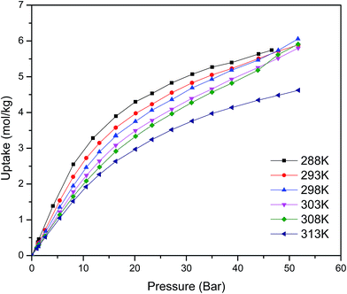
Fig. 1 shows the CO2 adsorption isotherms for FMOF-1 at near-ambient temperatures up to 55 bar. The maximum uptake experimentally measured is ca. 6.16 mol kg−1 (11.0 mol L−1; 27.1 wt%; 483 kg m−3; 248 V STP V−1) at 298 K and 55 bar. This uptake is more than 2 times higher than that predicted45 in 2008 based on the rigid structure of FMOF-1 reported in 2007,20 necessitating further modeling that takes into account the framework flexibility (vide infra). The isotherms do not reach a plateau and are inconsistent with a type I adsorption behaviour over this temperature and pressure range, again suggesting flexibility of the framework. This behaviour was determined not to be due to a systematic error in the experimental data, as it has been reproduced multiple times; see Fig. S2 (ESI†). Up to 30 bar, the isotherms can be fit very well with a Toth isotherm (Fig. S1†), and above this pressure the isotherms continue to rise, with a visible inflection at some temperatures.Upon removing the sample from the instrument after the CO2 adsorption studies, we noticed that the powder sample had transformed into a flat, yellow-coloured pellet. TGA and IR studies for pieces of such a pellet revealed essentially identical profiles to the powder sample of FMOF-1. We performed a contact angle experiment for a water droplet upon this pellet. This process proved difficult, as the water droplets tended to bounce and deflect off of the surface of the pellet rather quickly and as complete spheres, suggesting a rather extreme superhydrophobic behaviour of the material. Processing of the resulting image yielded a contact angle of ∼158, as shown in Fig. 2, clearly indicating a superhydrophobic behaviour and consistent with the insignificant water adsorption reported earlier for FMOF-1.46–48 The work herein, therefore, ascertains that FMOF-1 belongs to the “superhydrophobic” category of MOFs, similar to very few other frameworks verified as such from contact angle measurements.22,49,50
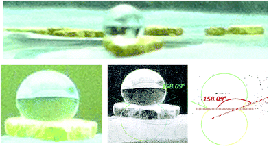 | ||
| Fig. 2 Images of a water drop on a pellet of FMOF-1 that formed after the high-pressure CO2 adsorption isotherm experiment shown in Fig. 1; most water droplets in the attempted contact angle experiments deflected off the surface of the pellet quickly as complete spheres. The bottom-right and bottom-middle images show the processing of the bottom-left raw image using the LBADSA plugin for the ImageJ software.51 | ||
Neutron diffraction studies
Neutron powder diffraction measurements were performed at the ORNL Spallation Neutrons and Pressure Diffractometer (SNAP) (Table S1†). Fig. 3a compares the neutron powder diffraction patterns for the evacuated FMOF-1 and the structure under 61 bar of CO2 at 290 K. Under this oversaturated pressure condition, the free CO2 molecules stay in the liquid state. The increase in intensity for the 011 peak at ∼13 Å after in situ CO2 loading is clearly discernible. The FMOF-1 sample with adsorbed CO2 was cooled to 230 K and the pressure was reduced to 4.8 bar for low-temperature measurements. The pressure in the TiZr cell was controlled via a computer-controlled gas handling system. Fig. S4 (ESI†) shows the evolution of the neutron powder diffraction patterns of the FMOF-1 sample with adsorbed CO2. No evidence of solid CO2 was observed in the structural refinement of the CO2 loaded samples, indicating that all CO2 was adsorbed into FMOF-1.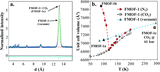 | ||
Fig. 3 (a) FMOF-1 neutron powder diffraction patterns measured at 290 K in vacuum (solid green line) and under 61 bar of CO2 (blue crosses). The residuals (cyan) underneath the zero line are the difference of the observed and refined neutron diffraction profiles of the FMOF-1 sample with adsorbed CO2. wR = 1.606%, GOF = 1.87, Nobs = 1658, Nvals = 14. Space group I![[4 with combining macron]](https://www.rsc.org/images/entities/char_0034_0304.gif) 2d, a = 13.9713(7) Å, c = 37.713(4) Å, V = 7361.4(7) Å3. (b) Temperature dependence of unit cell volume of FMOF-1 under vacuum,23 constant stream of N2 at atmospheric pressure23 and CO2 at 4.8 bar. The unit cell volume of FMOF-1 under 61 bar and 290 K (FMOF-1c) is also shown for comparison. 2d, a = 13.9713(7) Å, c = 37.713(4) Å, V = 7361.4(7) Å3. (b) Temperature dependence of unit cell volume of FMOF-1 under vacuum,23 constant stream of N2 at atmospheric pressure23 and CO2 at 4.8 bar. The unit cell volume of FMOF-1 under 61 bar and 290 K (FMOF-1c) is also shown for comparison. | ||
Fig. 3b shows the temperature dependence of the unit cell volume of FMOF-1 at a static pressure of 4.8 bar of CO2 loading and compares it with the results obtained under N2 stream23 and vacuum.23 The smooth change in the unit cell volume in CO2 (open squares) is in contrast to that of FMOF-1 with adsorbed N2 (red circles in Fig. 3b), in which the loading of N2 molecules into small cavities of FMOF-1 at temperatures below 119 K causes a huge negative thermal expansion in the crystal structure.23
FMOF-1 has two types of pores. The first type are large cylindrical channels extending along both the x- and y-directions (Fig. 4a and b), with CF3 groups protruding into the channels. The second pore type is a small cavity, and two pairs of CF3 groups function as a gate between the small cavity and the large cylindrical channel (see the red circle in Fig. 4c). The pore size distribution and full geometric characterization of FMOF-1 can be found in Fig. S5 and Table S2.†
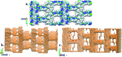 | ||
| Fig. 4 Schematic views of FMOF-1 channels. (a) Front view of FMOF-1 framework. C, cyan; F, white; N, blue and Ag, green. (b) Illustration of cylindrical channel voids using a 4 Å probe. The cylindrical channels extend along the x- and y-directions. (c) Representation of channel voids and small pockets protruding alongside the channels highlighted in red circles using a 1 Å probe. Views in (b) and (c) are calculated using the method described by Sarkisov and Harrison.52 | ||
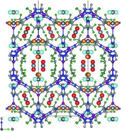
The favourable adsorption sites for CO2 molecules in FMOF-1 were obtained from difference Fourier map and with the CO2 molecules refined with distance constraints. Difference Fourier map from initial Rietveld refinements indicate that the CO2 molecules are located only in the large channels of FMOF-1 at three unique sites. The FMOF-1 structure loaded with CO2 molecules at 61 bar and 290 K is shown in Fig. 5. The oxygen atoms in the three primary CO2 adsorption sites are shown as cyan spheres at site I near the framework –CF3 groups at corners; as red spheres at site II near –CF3 groups along the crystallographic c direction; and as orange spheres at site III in the direction of the large channels. Since there is no CO2 in the small cavities, when all three CO2 adsorption sites are fully occupied, there are 24 CO2 molecules in the unit cell (3.3 mol kg−1). This limits the CO2 uptake capacity in the large cavity to 6 CO2 molecules per {Ag2[Ag4Tz6] repeat unit.
Molecular simulation studies and connection to experimental data
In order to verify our simulation parameters, we began by reproducing previously published experimental isotherms for benzene, n-hexane, and water in FMOF-1. Fig. 6 compares simulated results in FMOF-1a to the experimental isotherms. We see a very good agreement between simulation and experiment for benzene and hexane through the entire pressure range, with saturation loadings around 2 mol kg−1 and 1.2 mol kg−1, respectively. Additionally, both experiment and simulation show no appreciable adsorption of water, thereby confirming the hydrophobic nature of FMOF-1.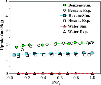 | ||
| Fig. 6 Simulated and experimental adsorption isotherms for benzene, n-hexane, and water in FMOF-1a at 298 K. P0 is the experimental saturation pressure of each adsorbate. | ||
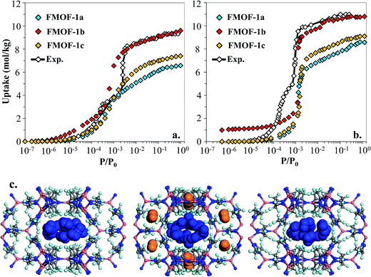
However, as shown in Fig. 7a and b, simulated isotherms of N2 and O2 adsorption in FMOF-1a drastically underpredict the saturation loading from experiment by almost 3 mol kg−1 in both cases. The N2 and O2 experimental isotherms show two steps, but the FMOF-1a simulated isotherms do not exhibit this behaviour. This pronounced step can be ascribed to the flexibility of the framework upon adsorption, meaning that N2 or O2 adsorption leads to structural changes of the framework, allowing for more molecules to be adsorbed in the framework. Similar adsorption isotherms have been observed in some ZIFs and the MIL series of MOFs due to framework flexibility.53–59 Since the framework is held rigid in our simulations, we approximated the effect of framework flexibility by simulating isotherms with three different FMOF-1 structures, FMOF-1a, FMOF-1b, and FMOF-1c. FMOF-1b has a larger unit cell volume and channel size than FMOF-1a; the largest cavity diameter in FMOF-1a is 6.1 Å, while in FMOF-1b it is 6.8 Å (see Table S2†). The channel size in FMOF-1c lies between FMOF-1a and FMOF-1b, with a 6.3 Å diameter. Recall from Fig. 3 that the unit cell volume of FMOF-1 varies with temperature and CO2 loading. Fig. 7 also shows adsorption isotherms of N2 and O2 in FMOF-1b and FMOF-1c. The two-step adsorption behaviour observed experimentally can be better described when the simulated isotherms of these different structures are considered. At low loadings, the FMOF-1a and FMOF-1c results agree better with experiment, while at high loadings the saturation loading in the expanded structure (i.e. FMOF-1b) is closer to experiment. The maximum amounts adsorbed in FMOF-1b for N2 and O2 are 9.6 and 10.7 mol kg−1, respectively, which are in excellent agreement with the experimental values.
The results shown in Fig. 7 corroborate that the framework of FMOF-1 goes through structural expansion upon adsorption of guest molecules. The small cavity in FMOF-1b has a diameter of ca. 3.4 Å, which is much larger than the small cavity in FMOF-1a or FMOF-1c (ca. 2.5 Å) (Table S2†). The kinetic diameters of N2 and O2 are 3.64 Å and 3.46 Å,3 respectively, which suggests that at most one N2 or O2 molecule can fit in each small pocket. Interestingly, the window sizes connecting the small pockets to the larger channels are smaller than the kinetic diameters of N2 and O2. However, kinetic diameters do not account for the orientation of the molecule – the cross section of a N2 or O2 molecule is ca. 2.9 Å,60 indicating that only FMOF-1b has a window size large enough to admit an N2 or O2 molecule. Additionally, since the FMOF-1b structure was obtained at 90 K and the isotherms are measured at 77 K, it is possible that the window size could also be larger at the lower temperature.
To investigate the placement of N2 within FMOF-1, we compared the position of N2 molecules adsorbed in the FMOF-1 structures at the saturation loading in the GCMC simulations at 77 K (Fig. 7c). In FMOF-1a and FMOF-1c, N2 molecules adsorb only in the large cylindrical channels. On the other hand, in FMOF-1b, the N2 molecules are adsorbed first in the small pockets at low pressures (Fig. S6†), and it is at the higher pressure that N2 molecules adsorb in the larger cylindrical channels. In FMOF-1b, molecules prefer to adsorb in the small pores due to the strong interactions between the adsorbed molecules and the Tz ring pairs, and only as the pressure increases do the large channels fill up. Given that only one N2 molecule can occupy each small pocket, the contribution of small pockets to the total amount adsorbed is 1.1 mol kg−1 (i.e., 8 molecules per unit cell of FMOF-1b). This uptake accounts for 11% of the total amount adsorbed. The remainder of the adsorption difference between FMOF-1b and FMOF-1c or FMOF-1a is due to additional adsorption in the large channels. As shown in Fig. S6,† a similar adsorption mechanism and placement was observed for O2 at 77 K. This finding further confirms that the structural expansion of FMOF-1 occurs not only in the small pockets but also increases the capacity of the larger channels for small adsorbates. It is worth mentioning that the simulated adsorption isotherms of larger adsorbates such as n-hexane and benzene in FMOF-1b and FMOF-1c show no significant differences when compared to the isotherm calculated for FMOF-1a (Fig. S7†). Toth fits for the n-hexane and benzene adsorption isotherms obtained for FMOF-1 agree very well with both the experimental data and the simulation thereof (Fig. S8a and S8b,† respectively). The kinetic diameters of n-hexane and benzene are 4.3 Å and 5.9 Å, respectively, both of which are much larger than the window and pore size of the small pockets. Therefore, the saturation loading of these large molecules is mainly determined by the volume of the cylindrical channels, resulting in a simple type-1 adsorption isotherm profile, with no adsorption in the smaller pores and no consequent steps in the adsorption isotherms. This finding further demonstrates that, while the accessibility of the smaller pockets and larger main channels for different expansion levels of FMOF-1 have significant effects on the adsorption properties of small adsorbates (e.g., N2, O2 and H2), these structural changes have little effect on the uptake of larger adsorbates (e.g., benzene, n-hexane, and toluene).
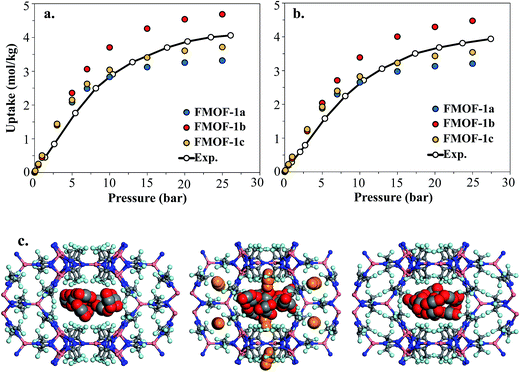
Fig. 8 shows the experimental CO2 adsorption isotherms in FMOF-1 structures at 278 K and 283 K, along with simulated data for comparison. This initial comparison is restricted to 30 bar, where the experimental isotherms can be fit with a Toth isotherm and FMOF-1 shows less pronounced flexibility and expansion. The simulated isotherms in all three structures agree reasonably well with the experimental data at low pressure. The difference between experiment and simulation increases for FMOF-1b as the pressure increases. At saturation loadings, better agreement between experiment and simulation results is observed for FMOF-1c, the structure that was obtained under the stream of CO2 (see Fig. 3). The simulation snapshots at high loading show that CO2 molecules occupy only the large channels in FMOF-1a and FMOF-1c, since the pockets are too small for CO2 (kinetic diameter: 3.4 Å). Interestingly, even in the expanded structure of FMOF-1b, the CO2 molecules cannot be fully accommodated inside the small pockets and stay at the windows connecting the large channels to the small pockets as highlighted in the simulation snapshots in Fig. 8c and the CO2 density profiles shown at high pressure in Fig. S9.†
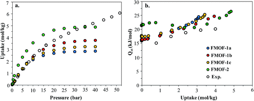
In order to better understand the CO2 adsorption behaviour in FMOF-1 at higher pressure (see Fig. 1), we also simulated CO2 adsorption isotherms at 298 K up to 50 bar for different FMOF-1a–c structures and compared the results to the simulated uptakes obtained for FMOF-2 and the experimental isotherm (Fig. 9a). The FMOF-2 structure is obtained from annealing FMOF-1 and recrystallizing from a toluene/acetonitrile solution and consists of two enlarged types of pores: hexagonal channels that are ca. 18 Å in width and triangular cages that are ca. 10 Å in diameter.46 The maximum amount adsorbed for CO2 at 298 K is 3.2 mol kg−1 or 23.4 molecules per unit cell in FMOF-1c. This value is in excellent agreement with the result from neutron powder diffraction experiments at 290 K, where CO2 uptake capacity of 3.3 mol kg−1 (24 molecules per unit cell) can be obtained when all three CO2 adsorption sites in the large cavity are fully occupied under 61 bar of CO2 loading (see Fig. 5). However, with a small increase in temperature, at 298 K, the simulated CO2 uptake is significantly lower than the experimental uptake even in the expanded FMOF-1b structure, suggesting further enlargement of the structure at this temperature. It is very clear from Fig. S2† that the CO2 adsorption of FMOF-1 at room temperature represents a marked deviation from the typical type 1 isotherm. Generally, Toth fit modeling is carried out on type 1 isotherms. In order to obtain a good Toth fit for the CO2 adsorption at room temperature, the pressure range is scaled down so as to compare experimental data with the simulation data. Fig. S10† shows that the Toth fit agrees well with the FMOF-1b structure. Indeed, the simulated saturation loading of CO2 in FMOF-2 shows better agreement with the experimental data at elevated pressures around 40 bar, suggesting expansion of FMOF-1 to a more expanded polymorph at higher pressures up to 60 bar. The collective experience of the Omary group with such M-Tz(RF)2 compositions suggests the prevalence of polymorphism and crystallographic isomerism; this is so both with and without gas adsorption assistance. As such, the presumed significant expansions (or compressions) suggested by the closer proximity of the experimental high-pressure CO2 uptake in FMOF-1 at ambient temperature to the simulated data for the porous-most “emptied” N2@FMOF-1 adsorption adduct at 90 K or – better yet – the FMOF-2 structure at 100 K should not be surprising for this highly flexible material.
Fig. 9b compares the isosteric heats of adsorption (Qst) obtained from GCMC simulations to the values obtained from variable-temperature experiments. The predicted Qst values were obtained from the fluctuations of the potential energy over the production cycles in the GCMC simulations for each pressure point. The experimental heats of adsorption were obtained using the Clausius–Clapeyron equation on isotherms from several temperatures (see ESI† for details). In reasonably good agreement with the experimental data, the simulated Qst values for the three FMOF-1 structures rise smoothly from ∼16 to 25 kJ mol−1 as the loading increases due to an increasing contribution from attractive CO2–CO2 interactions (Fig. S11†). The adsorption heats for FMOF-2 are higher (∼22 kJ mol−1) at low loadings due to strong adsorption of CO2 in the small triangular pores. In general, these moderate adsorption heats lie in the typical range for CO2 adsorption in MOFs.61,62 In Fig. S11,† the average adsorbate–adsorbent and adsorbate–adsorbate energies from GCMC simulations are shown for CO2 adsorption in FMOF-1c at 298 K as a function of pressure. The van der Waals interactions between CO2 and FMOF-1 are clearly dominant with ∼−12 kJ mol−1 contribution, and the coulombic components of the total interaction energy are very small, ∼−2 kJ mol−1. These results suggest that the fluorine-lined cylindrical pore creates an electrostatic potential that is not very favourable for CO2 adsorption.
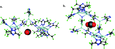
To provide another perspective on guest molecule interactions with FMOF-1, QM methods (UDFT with dispersion) employing cluster models were used to determine the free energy of binding for several guest molecules. The binding sites used in these calculations are located in the cylindrical channel and the small cavity. These sites are represented in Fig. 10 in the extended MOF structure with an overlay of the guest geometry from the cluster calculations.
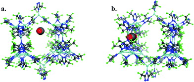 | ||
| Fig. 10 (a) CO2 in the cylindrical channel within the extended FMOF-1a structure and (b) CO2 in the small cavity within the extended FMOF-1b structure. | ||
The 184-atom extended model for the cylindrical channel binding site is taken from the FMOF-1a structure and shown in Fig. 11a. The extended model of the cylindrical channel with coordinated Ag and Tz was truncated with complete metal coordination spheres and ligands. By preserving the metal to ligand ratio, no atom substitutions were needed. The calculated binding free energies of CO2, N2, and H2 in the cylindrical channel are given in Table 1. The binding free energies follow the order CO2 > N2 > H2 in the cylindrical channel, indicating selective adsorption of CO2. The dispersion contribution increases the magnitude of the binding free energy by ∼59–66% in these calculations. Similar results with respect to the relative contribution of dispersion were found by Neaton for carbon dioxide binding in Mg–MOF-74.44
| Guest | Cylindrical channel | Small cavity | ||
|---|---|---|---|---|
| PBE0 (kJ mol−1) | PBE0-D3 (kJ mol−1) | PBE0 (kJ mol−1) | PBE0-D3 (kJ mol−1) | |
| CO2 | −9.2 | −23.2 | 138.6 | 94.5 |
| N2 | −7.9 | −19.3 | −9.0 | −39.6 |
| H2 | −2.1 | −6.6 | −3.5 | −16.8 |
The binding free energies in the small cavity of FMOF-1b were also determined for CO2, N2, and H2 using the truncated model shown in Fig. 11b. The small cavity shows stronger binding for N2 and H2 than in the cylindrical channel, with a similar dispersion correction making up 62–79% of the total binding free energy. The binding of CO2 in the truncated model of the small cavity is not energetically favourable, in agreement with GCMC simulations and neutron diffraction experimental results.
Effect of humidity on CO2 uptake
Finally, we consider the effect of humidity on the CO2 uptake of FMOF-1. Water is an ever-present component of flue gas, and we hypothesized that hydrophobic MOFs like FMOF-1 should show negligible loss of CO2 capacity in the presence of water vapor. To test this, we carried out GCMC simulations of CO2 adsorption in humid conditions. Fig. 12 depicts the excess amount adsorbed for a mixture of CO2 and H2O in FMOF-1c at 80% relative humidity and at different CO2 pressures. Although the CO2 uptake at 0.15 bar (the relevant condition in flue gas)63 is only ca. 0.05 mol kg−1 (0.3 molecules per unit cell), it is shown that for such a superhydrophobic MOF, the uptake of CO2 is not influenced by the presence of water vapor at all. There is essentially no co-adsorption of water in the presence of CO2, thereby explaining why the CO2 adsorption amount is similar under dry or humid conditions. This result supports the hypothesis that FMOFs can be promising to diminish the effect of humidity on CO2 adsorption performance.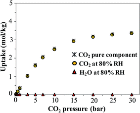 | ||
| Fig. 12 Simulated excess adsorption isotherms at 298 K for pure component CO2 and a mixture of CO2 at different pressures with water at 80% relative humidity in FMOF-1c. | ||
Conclusions
We combined atomically detailed calculations and experiments to provide insight into the adsorption of CO2 and other molecules in FMOF-1. First, the force field model for FMOF-1 was verified by comparing simulated adsorption isotherms for a variety of adsorbates in FMOF-1 with existing experimental data. Adsorption isotherms of N2 and O2 support previous suggestions that FMOF-1 undergoes major structural changes in the presence of guest molecules. This flexibility, however, has little effect on the loading of larger adsorbates such as n-hexane and benzene. The two-step isotherms observed for both N2 and O2 can be explained by analyzing simulated adsorption isotherms in both contracted and expanded FMOF-1 structures and the accessibility of the small pockets to these smaller adsorbates. We measured CO2 adsorption isotherms in FMOF-1 and found good agreement between experiment and simulations using the FMOF-1c structure at sub-ambient temperatures. Simulations of CO2 adsorption in FMOF-1 along with neutron powder diffraction measurements show that CO2 molecules cannot fit in the small pores of FMOF-1 and reside in the large channels at three distinct adsorption sites. The experimentally measured CO2 isotherms near and above room temperature suggest significant framework expansion at high CO2 pressures. Contact angle measurements confirm FMOF-1's previously reported hydrophobic nature, and Monte Carlo simulations predict no uptake of water even up to the vapor pressure of water. Simulations of CO2 adsorption in the presence of 80% relative humidity show that the amount of CO2 adsorbed is essentially the same as in the absence of humidity, validating our hypothesis that hydrophobic MOFs could hold promise for CO2 capture from flue gas.Conflict of interest
R. Q. S. has a financial interest in the start-up company NuMat Technologies, which is seeking to commercialize metal–organic frameworks.Acknowledgements
M. A. O. gratefully acknowledges support to his group's contributions by the Robert A. Welch Foundation (B-1542) and the National Science Foundation (Grant CHE-1413641 and its corresponding international supplement CHE-1545934), and thanks Dr Chi Yang for his efforts to initiate the discovery of FMOFs in the Omary group. R. Q. S. acknowledges support from the National Science Foundation (CBET-1604890). Computational work was supported by Northwestern University's shared computer system, Quest (Project: P20261). Research conducted at the ORNL Spallation Neutron Source was supported by the Scientific User Facilities division, Office of Basic Energy Sciences, US Department of Energy, under Contract DE-AC05-00OR22725 with UT-Battelle, LLC. A. K. W. acknowledges the research conducted at the UNT Center for Advanced Scientific Computing and Modeling, which was supported by the U.S. Department of Energy under DE-FG02-08ER64603.References
- R. S. Haszeldine, Carbon Capture and Storage: How Green Can Black Be?, Science, 2009, 325, 1647–1652 CrossRef CAS PubMed.
- D. J. Darensbourg, W.-C. Chung, K. Wang and H.-C. Zhou, Sequestering CO2 for Short-Term Storage in MOFs: Copolymer Synthesis with Oxiranes, ACS Catal., 2014, 4, 1511–1515 CrossRef CAS.
- J.-R. Li, R. J. Kuppler and H.-C. Zhou, Selective gas adsorption and separation in metal–organic frameworks, Chem. Soc. Rev., 2009, 38, 1477–1504 RSC.
- G. Ferey, Hybrid porous solids: past, present, future, Chem. Soc. Rev., 2008, 37, 191–214 RSC.
- S. Horike, S. Shimomura and S. Kitagawa, Soft porous crystals, Nat. Chem., 2009, 1, 695–704 CrossRef CAS PubMed.
- T. M. McDonald, J. A. Mason, X. Kong, E. D. Bloch, D. Gygi, A. Dani, V. Crocella, F. Giordanino, S. O. Odoh, W. S. Drisdell, B. Vlaisavljevich, A. L. Dzubak, R. Poloni, S. K. Schnell, N. Planas, K. Lee, T. Pascal, L. F. Wan, D. Prendergast, J. B. Neaton, B. Smit, J. B. Kortright, L. Gagliardi, S. Bordiga, J. A. Reimer and J. R. Long, Cooperative insertion of CO2 in diamine-appended metal–organic frameworks, Nature, 2015, 519, 303–308 CrossRef CAS PubMed.
- H. Furukawa, K. E. Cordova, M. O'Keeffe and O. M. Yaghi, The Chemistry and Applications of Metal–Organic Frameworks, Science, 2013, 341, 1230444 CrossRef PubMed.
- J. Liu, P. K. Thallapally, B. P. McGrail, D. R. Brown and J. Liu, Progress in adsorption-based CO2 capture by metal–organic frameworks, Chem. Soc. Rev., 2012, 41, 2308–2322 RSC.
- S. Keskin, T. M. van Heest and D. S. Sholl, Can Metal–Organic Framework Materials Play a Useful Role in Large-Scale Carbon Dioxide Separations?, ChemSusChem, 2010, 3, 879–891 CrossRef CAS PubMed.
- T. M. McDonald, W. R. Lee, J. A. Mason, B. M. Wiers, C. S. Hong and J. R. Long, Capture of Carbon Dioxide from Air and Flue Gas in the Alkylamine-Appended Metal–Organic Framework mmen-Mg2(dobpdc), J. Am. Chem. Soc., 2012, 134, 7056–7065 CrossRef CAS PubMed.
- C. E. Wilmer, O. K. Farha, Y.-S. Bae, J. T. Hupp and R. Q. Snurr, Structure–property relationships of porous materials for carbon dioxide separation and capture, Energy Environ. Sci., 2012, 5, 9849–9856 CAS.
- A. Ö. Yazaydın, R. Q. Snurr, T.-H. Park, K. Koh, J. Liu, M. D. LeVan, A. I. Benin, P. Jakubczak, M. Lanuza, D. B. Galloway, J. J. Low and R. R. Willis, Screening of Metal–Organic Frameworks for Carbon Dioxide Capture from Flue Gas Using a Combined Experimental and Modeling Approach, J. Am. Chem. Soc., 2009, 131, 18198–18199 CrossRef PubMed.
- S. R. Caskey, A. G. Wong-Foy and A. J. Matzger, Dramatic Tuning of Carbon Dioxide Uptake via Metal Substitution in a Coordination Polymer with Cylindrical Pores, J. Am. Chem. Soc., 2008, 130, 10870–10871 CrossRef CAS PubMed.
- J. Liu, A. I. Benin, A. M. B. Furtado, P. Jakubczak, R. R. Willis and M. D. LeVan, Stability Effects on CO2 Adsorption for the DOBDC Series of Metal–Organic Frameworks, Langmuir, 2011, 27, 11451–11456 CrossRef CAS PubMed.
- J. Canivet, A. Fateeva, Y. Guo, B. Coasne and D. Farrusseng, Water adsorption in MOFs: fundamentals and applications, Chem. Soc. Rev., 2014, 43, 5594–5617 RSC.
- P. Z. Moghadam, D. Fairen-Jimenez and R. Q. Snurr, Efficient identification of hydrophobic MOFs: application in the capture of toxic industrial chemicals, J. Mater. Chem. A, 2016, 4, 529–536 CAS.
- P. Deria, J. E. Mondloch, E. Tylianakis, P. Ghosh, W. Bury, R. Q. Snurr, J. T. Hupp and O. K. Farha, Perfluoroalkane Functionalization of NU-1000 via Solvent-Assisted Ligand Incorporation: Synthesis and CO2 Adsorption Studies, J. Am. Chem. Soc., 2013, 135, 16801–16804 CrossRef CAS PubMed.
- J. B. Decoste, G. W. Peterson, M. W. Smith, C. A. Stone and C. R. Willis, Enhanced Stability of Cu-BTC MOF via Perfluorohexane Plasma-Enhanced Chemical Vapor Deposition, J. Am. Chem. Soc., 2012, 134, 1486–1489 CrossRef CAS PubMed.
- P. Z. Moghadam, P. Ghosh and R. Q. Snurr, Understanding the Effects of Preadsorbed Perfluoroalkanes on the Adsorption of Water and Ammonia in MOFs, J. Phys. Chem. C, 2015, 119, 3163–3170 CAS.
- C. Yang, X. Wang and M. A. Omary, Fluorous Metal–Organic Frameworks for High-Density Gas Adsorption, J. Am. Chem. Soc., 2007, 129, 15454–15455 CrossRef CAS PubMed.
- C. Serre, Superhydrophobicity in Highly Fluorinated Porous Metal–Organic Frameworks, Angew. Chem., Int. Ed., 2012, 51, 6048–6050 CrossRef CAS PubMed.
- T.-H. Chen, I. Popov, O. Zenasni, O. Daugulis and O. S. Miljanic, Superhydrophobic perfluorinated metal–organic frameworks, Chem. Commun., 2013, 49, 6846–6848 RSC.
- C. Yang, X. Wang and M. A. Omary, Crystallographic Observation of Dynamic Gas Adsorption Sites and Thermal Expansion in a Breathable Fluorous Metal–Organic Framework, Angew. Chem., Int. Ed., 2009, 48, 2500–2505 CrossRef CAS PubMed.
- B. Schmitz, U. Müller, N. Trukhan, M. Schubert, G. Férey and M. Hirscher, Heat of Adsorption for Hydrogen in Microporous High-Surface-Area Materials, ChemPhysChem, 2008, 9, 2181–2184 CrossRef CAS PubMed.
- B. H. Toby and R. B. Von Dreele, GSAS-II: the genesis of a modern open-source all purpose crystallography software package, J. Appl. Crystallogr., 2013, 46, 544–549 CrossRef CAS.
- J. J. Potoff and J. I. Siepmann, Vapor–liquid equilibria of mixtures containing alkanes, carbon dioxide, and nitrogen, AIChE J., 2001, 47, 1676–1682 CrossRef CAS.
- L. Zhang and J. I. Siepmann, Direct calculation of Henry's law constants from Gibbs ensemble Monte Carlo simulations: nitrogen, oxygen, carbon dioxide and methane in ethanol, Theor. Chem. Acc., 2006, 115, 391–397 CrossRef CAS.
- M. G. Martin and J. I. Siepmann, Transferable Potentials for Phase Equilibria. 1. United-Atom Description of n-Alkanes, J. Phys. Chem. B, 1998, 102, 2569–2577 CrossRef CAS.
- N. Rai and J. I. Siepmann, Transferable Potentials for Phase Equilibria. 9. Explicit Hydrogen Description of Benzene and Five-Membered and Six-Membered Heterocyclic Aromatic Compounds, J. Phys. Chem. B, 2007, 111, 10790–10799 CrossRef CAS PubMed.
- W. L. Jorgensen, J. Chandrasekhar, J. D. Madura, R. W. Impey and M. L. Klein, Comparison of simple potential functions for simulating liquid water, J. Chem. Phys., 1983, 79, 926–935 CrossRef CAS.
- A. K. Rappe, C. J. Casewit, K. S. Colwell, W. A. Goddard and W. M. Skiff, UFF, a full periodic table force field for molecular mechanics and molecular dynamics simulations, J. Am. Chem. Soc., 1992, 114, 10024–10035 CrossRef CAS.
- V. H. Dalvi, V. Srinivasan and P. J. Rossky, Understanding the Effectiveness of Fluorocarbon Ligands in Dispersing Nanoparticles in Supercritical Carbon Dioxide, J. Phys. Chem. C, 2010, 114, 15553–15561 CAS.
- C. M. Breneman and K. B. Wiberg, Determining atom-centered monopoles from molecular electrostatic potentials. The need for high sampling density in formamide conformational analysis, J. Comput. Chem., 1990, 11, 361–373 CrossRef CAS.
- M. Valiev, E. J. Bylaska, N. Govind, K. Kowalski, T. P. Straatsma, H. J. J. Van Dam, D. Wang, J. Nieplocha, E. Apra, T. L. Windus and W. A. de Jong, NWChem: A comprehensive and scalable open-source solution for large scale molecular simulations, Comput. Phys. Commun., 2010, 181, 1477–1489 CrossRef CAS.
- C. Adamo and V. Barone, Toward reliable density functional methods without adjustable parameters: The PBE0 model, J. Chem. Phys., 1999, 110, 6158–6170 CrossRef CAS.
- R. Krishnan, J. S. Binkley, R. Seeger and J. A. Pople, Self-consistent molecular orbital methods. XX. A basis set for correlated wave functions, J. Chem. Phys., 1980, 72, 650–654 CrossRef CAS.
- W. J. Hehre, R. Ditchfield and J. A. Pople, Self—Consistent Molecular Orbital Methods. XII. Further Extensions of Gaussian—Type Basis Sets for Use in Molecular Orbital Studies of Organic Molecules, J. Chem. Phys., 1972, 56, 2257–2261 CrossRef CAS.
- M. Kaupp, P. V. R. Schleyer, H. Stoll and H. Preuss, Pseudopotential approaches to Ca, Sr, and Ba hydrides. Why are some alkaline earth MX2 compounds bent?, J. Chem. Phys., 1991, 94, 1360–1366 CrossRef CAS.
- S. Grimme, J. Antony, S. Ehrlich and H. Krieg, A consistent and accurate ab initio parametrization of density functional dispersion correction (DFT-D) for the 94 elements H-Pu, J. Chem. Phys., 2010, 132, 154104 CrossRef PubMed.
- J. Joo, H. Kim and S. S. Han, Volume shrinkage of a metal–organic framework host induced by the dispersive attraction of guest gas molecules, Phys. Chem. Chem. Phys., 2013, 15, 18822–18826 RSC.
- J. A. Gee and D. S. Sholl, Prediction of Adsorption Properties of Cyclic Hydrocarbons in MOFs Using DFT-Derived Force Fields, J. Phys. Chem. C, 2015, 119, 16920–16926 CAS.
- B. K. Chang, N. C. Bristowe, P. D. Bristowe and A. K. Cheetham, van der Waals forces in the perfluorinated metal–organic framework zinc 1,2-bis(4-pyridyl)ethane tetrafluoroterephthalate, Phys. Chem. Chem. Phys., 2012, 14, 7059–7064 RSC.
- K. Lee, J. D. Howe, L.-C. Lin, B. Smit and J. B. Neaton, Small-Molecule Adsorption in Open-Site Metal–Organic Frameworks: A Systematic Density Functional Theory Study for Rational Design, Chem. Mater., 2015, 27, 668–678 CrossRef CAS.
- R. Poloni, B. Smit and J. B. Neaton, CO2 Capture by Metal–Organic Frameworks with van der Waals Density Functionals, J. Phys. Chem. A, 2012, 116, 4957–4964 CrossRef CAS PubMed.
- R. Babarao and J. Jiang, Molecular Screening of Metal–Organic Frameworks for CO2 Storage, Langmuir, 2008, 24, 6270–6278 CrossRef CAS PubMed.
- C. Yang, U. Kaipa, Q. Z. Mather, X. Wang, V. Nesterov, A. F. Venero and M. A. Omary, Fluorous Metal–Organic Frameworks with Superior Adsorption and Hydrophobic Properties toward Oil Spill Cleanup and Hydrocarbon Storage, J. Am. Chem. Soc., 2011, 133, 18094–18097 CrossRef CAS PubMed.
- N. Nijem, P. Canepa, U. Kaipa, K. Tan, K. Roodenko, S. Tekarli, J. Halbert, I. W. H. Oswald, R. K. Arvapally, C. Yang, T. Thonhauser, M. A. Omary and Y. J. Chabal, Water Cluster Confinement and Methane Adsorption in the Hydrophobic Cavities of a Fluorinated Metal–Organic Framework, J. Am. Chem. Soc., 2013, 135, 12615–12626 CrossRef CAS PubMed.
- N. Nijem and Y. J. Chabal, Adsorbate Interactions in Metal Organic Frameworks Studied by Vibrational Spectroscopy, Comments Inorg. Chem., 2014, 34, 78–102 CrossRef CAS.
- J. G. Nguyen and S. M. Cohen, Moisture-Resistant and Superhydrophobic Metal–Organic Frameworks Obtained via Postsynthetic Modification, J. Am. Chem. Soc., 2010, 132, 4560–4561 CrossRef CAS PubMed.
- K. P. Rao, M. Higuchi, K. Sumida, S. Furukawa, J. Duan and S. Kitagawa, Design of Superhydrophobic Porous Coordination Polymers through the Introduction of External Surface Corrugation by the Use of an Aromatic Hydrocarbon Building Unit, Angew. Chem., Int. Ed., 2014, 53, 8225–8230 CrossRef CAS PubMed.
- A. F. Stalder, T. Melchior, M. Müller, D. Sage, T. Blu and M. Unser, Low-bond axisymmetric drop shape analysis for surface tension and contact angle measurements of sessile drops, Colloids Surf., A, 2010, 364, 72–81 CrossRef CAS.
- L. Sarkisov and A. Harrison, Computational structure characterisation tools in application to ordered and disordered porous materials, Mol. Simul., 2011, 37, 1248–1257 CrossRef CAS.
- D. Fairen-Jimenez, S. A. Moggach, M. T. Wharmby, P. A. Wright, S. Parsons and T. Düren, Opening the Gate: Framework Flexibility in ZIF-8 Explored by Experiments and Simulations, J. Am. Chem. Soc., 2011, 133, 8900–8902 CrossRef CAS PubMed.
- F.-X. Coudert, A. Boutin, A. H. Fuchs and A. V. Neimark, Adsorption Deformation and Structural Transitions in Metal–Organic Frameworks: From the Unit Cell to the Crystal, J. Phys. Chem. Lett., 2013, 4, 3198–3205 CrossRef CAS.
- W. Cai, T. Lee, M. Lee, W. Cho, D.-Y. Han, N. Choi, A. C. K. Yip and J. Choi, Thermal Structural Transitions and Carbon Dioxide Adsorption Properties of Zeolitic Imidazolate Framework-7 (ZIF-7), J. Am. Chem. Soc., 2014, 136, 7961–7971 CrossRef CAS PubMed.
- L. Sarkisov, R. L. Martin, M. Haranczyk and B. Smit, On the Flexibility of Metal–Organic Frameworks, J. Am. Chem. Soc., 2014, 136, 2228–2231 CrossRef CAS PubMed.
- K. Zhang, R. P. Lively, C. Zhang, R. R. Chance, W. J. Koros, D. S. Sholl and S. Nair, Exploring the Framework Hydrophobicity and Flexibility of ZIF-8: From Biofuel Recovery to Hydrocarbon Separations, J. Phys. Chem. Lett., 2013, 4, 3618–3622 CrossRef CAS.
- N. Nijem, H. Wu, P. Canepa, A. Marti, K. J. Balkus, T. Thonhauser, J. Li and Y. J. Chabal, Tuning the Gate Opening Pressure of Metal–Organic Frameworks (MOFs) for the Selective Separation of Hydrocarbons, J. Am. Chem. Soc., 2012, 134, 15201–15204 CrossRef CAS PubMed.
- A. Schneemann, V. Bon, I. Schwedler, I. Senkovska, S. Kaskel and R. A. Fischer, Flexible metal–organic frameworks, Chem. Soc. Rev., 2014, 43, 6062–6096 RSC.
- C. E. Webster, R. S. Drago and M. C. Zerner, Molecular Dimensions for Adsorptives, J. Am. Chem. Soc., 1998, 120, 5509–5516 CrossRef CAS.
- J.-R. Li, Y. Ma, M. C. McCarthy, J. Sculley, J. Yu, H.-K. Jeong, P. B. Balbuena and H.-C. Zhou, Carbon dioxide capture-related gas adsorption and separation in metal–organic frameworks, Coord. Chem. Rev., 2011, 255, 1791–1823 CrossRef CAS.
- J. M. Simmons, H. Wu, W. Zhou and T. Yildirim, Carbon capture in metal–organic frameworks-a comparative study, Energy Environ. Sci., 2011, 4, 2177–2185 CAS.
- Y.-S. Bae and R. Q. Snurr, Development and Evaluation of Porous Materials for Carbon Dioxide Separation and Capture, Angew. Chem., Int. Ed., 2011, 50, 11586–11596 CrossRef CAS PubMed.
Footnotes |
| † Electronic supplementary information (ESI) available. See DOI: 10.1039/c7sc00278e |
| ‡ P. Z. M., J. F. I., and R. K. A. contributed equally (co-1st authors). |
| This journal is © The Royal Society of Chemistry 2017 |

