 Open Access Article
Creative Commons Attribution 3.0 Unported Licence
Design and 3D printing of a stainless steel reactor for continuous difluoromethylations using fluoroform†
Bernhard
Gutmann
ab,
Manuel
Köckinger
ab,
Gabriel
Glotz
ab,
Tania
Ciaglia
a,
Eyke
Slama
b,
Matej
Zadravec
b,
Stefan
Pfanner
c,
Manuel C.
Maier
bd,
Heidrun
Gruber-Wölfler
 bd and
C.
Oliver Kappe
 *ab
*ab
aInstitute of Chemistry, University of Graz, NAWI Graz, Heinrichstrasse 28, 8010 Graz, Austria. E-mail: oliver.kappe@uni-graz.at
bCenter for Continuous Flow Synthesis and Processing (CC FLOW), Research Center Pharmaceutical Engineering GmbH (RCPE), Inffeldgasse 13, Graz, Austria
cAnton Paar, Anton-Paar-Straße 20, 8054 Graz, Austria
dInstitute of Process and Particle Engineering, Graz University of Technology, Inffeldgasse 13, 8010 Graz, Austria
First published on 9th November 2017
Abstract
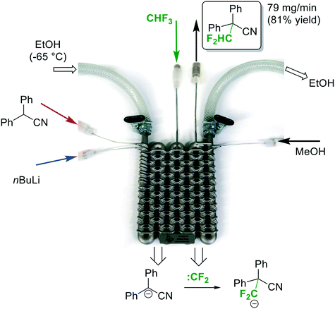
Herein we present a continuous flow reactor printed from stainless steel by selective laser melting. The reactor was specifically designed for a fast difluoromethylation reaction with nBuLi as base and fluoroform as atom-economic and inexpensive reagent. The reactor features four inlets to allow introduction of substrate, nBuLi, fluoroform, and a final quench solution. The reaction was completed within less than 2 min at −65 °C. The utilization of stainless steel as reactor material is critical to accomplish the heat transfer as well as the chemical and mechanical resistance that is required for this transformation.
Introduction
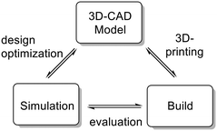
Continuous flow micro- and milli-reactors have found increasingly wide applications in organic synthesis on all scales.1,2 The rapidly growing interest can be attributed to a range of advantages offered by these devices. Compared to traditional batch reactors, continuous flow microreactors typically exhibit enhanced heat and mass transfer, improved safety, and higher levels of controllability.1 Furthermore, multiple reaction steps, purification steps and analysis can be combined into a single continuous production unit.2,3 The flow systems are usually assembled from relatively simple, off-the-shelf components, such as polymer or metal tubings in combination with standard connectors to join these pieces together (such as those used in standard high performance liquid chromatography (HPLC) instruments).1 These components, while readily available and cheap, allow only limited design complexity for microfluidic applications. More elaborate architectures are accomplished within microreactors. Microreactors are commercially available in various pre-determined designs and from various inert materials (most commonly glass, stainless steel/Hastelloy, or silicon carbide ceramic).4 These reactors are typically manufactured by well-developed mass-production techniques, such as micromachining, laser ablation, or etching, with little possibilities for customization.4 In recent years, researchers have explored rapid prototyping technologies to construct more complex, customized microreactors.5 Several structural elements, such as mixing structures, residence time channels, separation units, and interfaces for in-line analysis, have been incorporated into these devices.5 So far, the majority of these reactors have been fabricated from poly(dimethylsiloxane) (PDMS) using soft lithography.5 Soft lithography is a rather complex, multistep process which is applicable for the fabrication of planar, two-dimensional microreactors (structures with varying width but identical depth). The fabrication of more elaborate, truly three-dimensional geometries significantly increases the number of production steps and, consequently, production time. The main limitation of PDMS reactors is the low chemical compatibility with organic solvents. Furthermore, the low mechanical strength and the low temperature stability prevent applications at elevated pressures and temperatures.5 These devices, while extensively used for biochemical and analytical applications (e.g. gene sequencing and point-of-care diagnostics), have, thus, found only limited use in organic synthesis.5 Compared to soft lithography, additive manufacturing (a.k.a. 3D printing) is more automated, faster, and, furthermore, allows the fabrication of reactors of nearly arbitrary complexity.6,7 For additive manufacturing, a virtual model is initially created in a 3D graphics software. This model is then used to directly build the 3-dimensional structure layer-by-layer, typically without the need for any further planning of the manufacturing process. These manufacturing techniques provide virtually full design freedom and allow fabrication of microreactors with complete control over mixing structures, mixing points, flow paths, and residence volumes. The 3D CAD file is easily shared with collaborators for examination and, additionally, can form the basis for finite element analysis and computer-assisted design optimization (Fig. 1). Despite the many advantages of 3D printing, applications for the construction of microreactors are still surprisingly rare.7–9 Most of the devices reported so far are printed by fused deposition modeling,8 and stereolithography.9 While comparatively cheap, these techniques are currently restricted to polymer-based materials which exhibit low stability against a range of reagents and common organic solvents, such as aromatic solvents, ethers and chloroform.10 Moreover, the low thermal conductivity limits applications to reactions which proceed at room temperature and do not release a lot of heat. With the emergence of high-power lasers for additive manufacturing, parts can now be printed from a variety of metals by selective laser melting (SLM).11 These materials provide the thermal conductivity as well as chemical, mechanical and thermal stability required for applications in organic synthesis.11–14 Utilization of SLM techniques for the fabrication of continuous flow microreactors have been recently reported from the laboratories of Edmondson and Christie.12 A printed reactor from a titanium alloy was coupled with online monitoring for automated optimization of two model reactions.12b Additionally, Innosyn announced customized 3D printed continuous flow reactors from metals.13 Specific applications of those reactors for synthesis have not been published so far.Our group has recently become interested in fast, late-stage difluoromethylation and trifluoromethylation reactions performed under scalable continuous flow conditions.15,16 The most attractive difluoromethyl-source, from an economic and environmental perspective, is fluoroform (CHF3, Freon 23). Fluoroform, a nontoxic and ozone-friendly gas (bp −82 °C), is generated as a large-volume waste-product during the production of fluoropolymers. Due to its extraordinarily low reactivity, however, it has very little current use. Only recently the first synthetically relevant transformations with fluoroform as reagent have started to emerge.17 We have become particularly interested by a difluorormethylation reaction developed in the laboratories of Mikami.18 The protocol generates difluorocarbene by a fast deprotonation of fluoroform with rapid subsequent α-elimination of fluoride. The difluorocarbene then reacts with the anion of the substrate (Fig. 2). Both reactions are exothermic and fast, even at sub-ambient temperatures. Herein we report the design and manufacturing of a millifluidic flow reactor specifically designed for this reaction. A reliable and robust reactor was produced from stainless steel by selective laser melting (SLM). The reactor features four inlets to combine the substrate feed with two reagent feeds and a final quench solution. The reaction was performed at a reaction temperature of −65 °C to generate the desired product in excellent yields after a total reaction time of less than 2 min.
Results and discussion
Reactor design
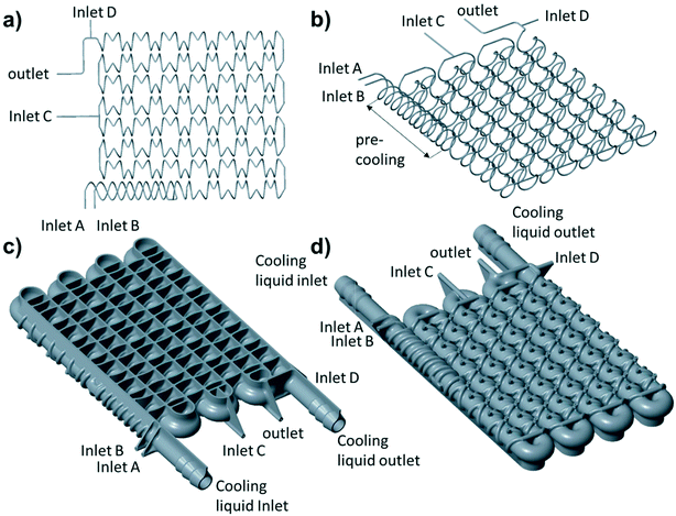
To accomplish the desired difluoromethylation reaction, three inlets for substrate, nBuLi and CHF3 are required (Fig. 2 and 3). The reaction commences with a rapid deprotonation of the substrate with nBuLi at sub-ambient temperatures. Mikami and co-workers performed the first reaction step in a batch vessel on a scale of 0.5 mmol at a reaction temperature of −78 °C.18 The reaction time for the deprotonation step was reported to be 5 min.18 Preliminary experiments from our laboratories suggested that the deprotonation step is completed after a reaction time of only 1 min. After the deprotonation step, the reaction mixture needs to be combined with gaseous CHF3. The reaction time for the reaction with CHF3 was also reported to be around one minute at −78 °C.18 Finally, we decided to have a forth inlet for a quench solution near the outlet of the reactor (Fig. 2 and 3). The quench solution (MeOH) stops the reaction and destroys any excess of base before the reaction stream exits the reactor for collection and analysis. Furthermore, batch experiments demonstrated that small amounts of a precipitate are formed during the reaction (probably LiF). The quench solution is also used to re-dissolve the precipitate at the end of the reactor to avoid accumulation at and eventually blockage of the back pressure regulator. Initial test-prints of cylindrical channels with 10 mm length and internal diameters ranging from 0.5 mm to 2.4 mm demonstrated that the SLM process reliably reproduces channels of around 0.6 mm diameter from the initial CAD model (see Fig. S1 and S2 in the ESI†). We opted for channels with an inner diameter of 0.8 mm (outer diameter of 2.4 mm) to facilitate drainage of the remaining powder from the channels after printing and, furthermore, to reduce risks of blockage during difluoromethylation reactions. The reaction channel was designed with a slightly oval cross section. This geometry yields better surface quality on the top surface of the reaction channel by reducing the printing area that overhangs into the metal powder (see Fig. S1 and S2 in the ESI†). With an envisaged throughput of 0.5 mmol min−1 at a concentration of ∼0.5 M and a reaction time of 1 min for each reaction step, channels of 2 meter length at a diameter of 0.8 mm are required for both reaction zones. The reactor was designed with meandering channels, giving a curvature-based mixing geometry (Fig. 3a). Similar two dimensional meandering channels are widely used in commercial microreactors.13,19 The zig-zag nature of the channels has been demonstrated to enhance advective mixing by stretching and folding of the flow stream.13 For the reactor presented herein, the meandering channels are drawn onto the cooling element, thus producing the 3-dimensional channel geometry shown in Fig. 3b. The direct attachment of the reaction channel onto the cooling element reduces heat transport distances and facilitates cooling. The cooling element was designed as a single tube in serpentine form with an inner diameter of 7 mm (outer diameter of 9 mm). Standard hose connectors were attached on both ends of the cooling tube to allow simple connection with a circulation cryostat (Fig. 3c and d). The two reaction channels for the substrate (inlet A) and the nBuLi feed (inlet B) are first guided like threads around the tube of the cooling element (pre-cooling zone), before they are brought together in a T-junction. The T-junction is followed by a reaction channel of 0.9 mL volume. A second T-junction then combines the reaction channel with the third inlet channel (inlet C for CHF3). After a second reaction channel of 1 mL residence volume, a third T-junction is integrated to allow the introduction of the quench solution (inlet D). A support structure was incorporated at the bottom of the build (Fig. 3c). The support structure ensures adhesion of the printed components to the build platform and minimizes curling and distortion due to residual welding stresses.CFD simulation
An especially attractive feature of rapid prototyping techniques is that the initial CAD file can be easily shared and digitally inspected by experts in remote locations. The file can form the basis of finite-volume simulations to examine expected mechanical properties or mixing performance. We used computational fluid dynamics (CFD) simulation to evaluate the mixing geometry. The set of governing equations (i.e. Navier–Stokes equations) was solved using the Ansys-CFX software package. Boundary conditions were set to match the anticipated experimental conditions. Thus, for inlet A a flow rate of 0.8 mL min−1 and for inlet B a flow rate of 0.36 mL min−1 was considered (Fig. 4). The simulation was performed as steady-state simulation. Fig. 4 shows the contour plots for the flow vorticity (top) and flow streamlines (bottom) at different cut planes along the flow path. From the streamline results, it is seen that the flow is represented by several vortices on each plane, which causes good mixing perpendicular to the main stream direction along the reaction channel. Fig. 4 also presents contour plots of flow vorticity (top) on different cut planes. The vorticity field exhibit two "poles" of opposite oriented vorticity fields. The opposing rotations of fluid in a given cross-section are expected to contribute to the mixing performance.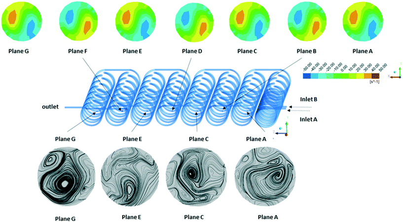 | ||
| Fig. 4 Contour plots of flow vorticity (top) and flow streamlines (bottom) at different cut planes (inner diameter of the channel is 0.8 mm). | ||
Reactor printing and characterization
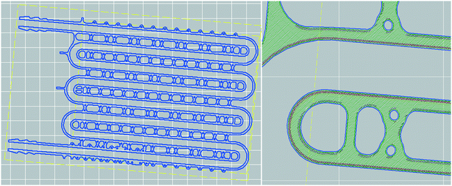
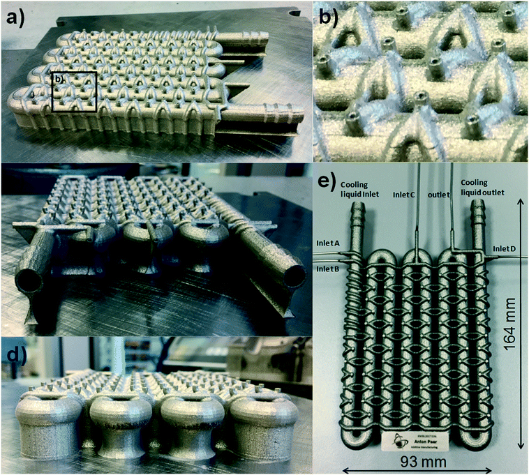
For the SLM process, the 3D CAD model is dissected by the process software into a series of cross-sectional slices. The slices are then printed layer-by-layer by fusion of the metal powder (Fig. 5). Selective laser melting (SLM) is currently one of the most powerful 3D printing technologies.6 An increasing number of metal and alloys can be used, including aluminum, copper, stainless steel, hastelloy, tantalum and tungsten.6 These materials provide good chemical stability in addition to excellent temperature and pressure resistance. Furthermore, the materials deliver the thermal conductivity necessary for adequate heat transfer. The reactor present herein was printed with a SLM system from EOS (Fig. S5 in the ESI†).20 As metal powder, a 316 L stainless steel powder with a median particle size of 43.5 μm was utilized (Fig. S6 in the ESI†). The SLM instrument uses an Ytterbium fiber laser with 400 Watt maximum power to fuse the stainless steel powder as it scans across the build area. After the designated areas of the layer have been exposed, the build plate is lowered by 50 μm and another layer of powder is dispensed over the object. The machine then proceeds to scan the next slice cross-section (Fig. 5). The thermal energy of the laser is sufficient to melt to a depth exceeding the layer thickness. Thus, a portion of the previously solidified structure is re-melted to generate a well-bonded, gas-tight, high-density build.6 The printing process takes place inside an enclosed chamber filled with nitrogen to avoid oxidation and degradation of the material.At the end of the printing process, the freshly printed reactor is retrieved from the bed and the powder is dusted off with compressed air. In contrast to extrusion based printing technologies, SLM does not need secondary support structures for overhangs and undercuts as the printed structure is supported by the surrounding powder bed. This feature enables greater design freedom compared to other printing technologies. However, after the fabrication process the remaining powder needs to be drained from hollow spaces. To facilitate clearance of the reaction channel, shortcut holes were incorporated at every turn (Fig. 6a and b). With the help of these shortcut holes, the remaining metal powder could be removed without any difficulties from the channels with compressed air. After the channels were cleared and the reactor was cleaned with ultrasound, the holes were closed by laser beam welding and 1/16′′ stainless steel tubings were attached onto the inlets and outlets (Fig. 6e). The tubings were finally equipped with standard 1/16′′ fittings to allow simple integration with peripheral flow equipment (pumps, backpressure regulator and mass flow controller). Unused powder remains unaffected in the SLM process and is recovered for the next 3D print. In total, the printing process took about 14 hours to complete.
To determine the residence time distribution (RTD) in the reactor, a step experiment was performed (see Fig. S7 and S8 in the ESI†). The build resolution and surface roughness of SLM is still relatively poor compared to conventional manufacturing techniques such as computer-numerically controlled machining (CNC). The surface roughness could have a detrimental effect on the RTD. To measure the RTD, inlet A was connected to a syringe pump (Asia Syrris), while the other inlets were closed. A 10−3 M aqueous solution of Rose Bengal was pumped through the reactor with a flow rate of 1 mL min−1. A fast switch from the Rose Bengal solution to water was carried out by means of a three-way valve, while maintaining a flowrate of 1 mL min−1. The concentration of Rose Bengal at the outlet was measured in-line with an in-house developed photometer. From the experimental data, the Bodenstein number for the open-open vessel condition was found to be 31.44. The Bodenstein number and the narrow exit age distribution suggest moderate axial dispersion throughout the reactor, without retention of material, channeling or unexpected dead volumes (see Fig. S7 and S8 in the ESI†). In addition, the residence volume was determined to be 1.85 mL and, thus, corresponds very well with the design volume of 1.89 mL, indicating good clearance of the reaction channel and high dimensional accuracy.21
Chemistry
For the difluoromethylation reaction, the inlets A, B and D were attached with standard connectors to three syringe pumps (Asia Syrris). Inlet C was connected via a calibrated mass flow controller (Bronkhorst) to the fluoroform gas cylinder, and the outlet was connected to a backpressure regulator (Swagelok 0–25 bar). Finally, the cooling element was attached in a parallel flow arrangement to the circulation cryostat (Fig. 7). Diphenylacetonitrile was used a model substrate for the difluoromethylation reaction to demonstrate the performance of the printed reactor. The reaction conditions for the flow difluoromethylation were chosen to resemble those reported by Mikami and co-workers.18 A comprehensive re-optimization of the reaction conditions was not attempted at this stage. Thus, the reactor was cooled by the cryostat to a temperature of −65 °C. A 0.5 M solution of diphenylacetonitrile was pumped into Inlet A with a flow rate of 0.8 mL min−1, while a commercial solution of nBuLi in hexane (2.5 M) was pumped directly from the supply bottle into Inlet B with a flow rate of 0.36 mL min−1 (Fig. 7). With these flow rates a 2.25 fold excess of nBuLi and a nominal residence time of ∼50 s in the first reaction zone were obtained. After the first reaction zone the mixture was combined with the fluoroform gas at a flow rate of 26.7 mL min−1 (flow rate at standard conditions; 3 equivalents). Preceding experiments with CHF3 in continuous flow reactors made of Teflon tubings demonstrated that the gas is completely dissolved in the liquid phase at this temperature. In the second zone of the reactor, the fluoroform is deprotonated by the remaining nBuLi and the resulting unstable trifluoromethanide anion subsequently loses a fluoride ion in an α-elimination to generate a short-lived singlet difluorocarbene (CF3− → :CF2 + F−). The electrophilic singlet difluorocarbene then reacts with the deprotonated substrate (Fig. 7). The nominal residence time in the second reactor zone is ∼1 min. At Inlet D, the reaction mixture is finally combined with a quench solution of MeOH at a flow rate of 1 mL min−1 before it left the reactor through the outlet and a backpressure regulator at 5 bar. The product was formed with 95% selectivity in this reaction according to GC-FID (see Experimental section for details). The collected mixture was then extracted with Et2O/H2O, the solvent evaporated and the crude product finally recrystallized from n-hexane. 4 mL of starting material were processed in a continuous run to afford 395 mg of the desired difluoromethylated product in excellent purity and 81% yield.Conclusion
With the development of new materials for additive manufacturing, such as various metals, alloys, and ceramics, and improving accuracy and quality of the outputs, the production of customized, functional end-products has become increasingly feasible. Even though these technologies are still rarely applied in organic synthesis, recent examples demonstrate that chemical reactors of almost arbitrary complexity can be produced.7–9,12,13 Herein we presented the design and 3D printing of a continuous flow reactor by selective laser melting (SLM) of stainless steel powder. The utilization of stainless steel enables fast heat transfer and high pressure resistance, thus, allowing the execution of exothermic reactions at cryogenic temperatures and elevated pressures. Furthermore, reactors printed from stainless steel allow the utilization of reagents/solvents which would be destructive to the majority of materials commonly used for other rapid prototyping techniques (such as PDMS). The reactor was specifically designed for a two-step difluoromethylation reaction with gaseous fluoroform. This reaction produces the desired product in excellent purity after a total reaction time of less than 2 min at a reaction temperature of −65 °C. It can be expected that additive manufacturing and related direct digital manufacturing technologies, in combination with computational chemical reaction and fluid dynamics simulation, will play a fundamental role in the design of next-generation, continuous flow microreactors. Further work is planned in our laboratories to integrate in-line analysis into the reactor and to further explore difluroromethylation chemistry with fluoroform and other multiphase (g/l) reactions.Experimental
Reactor design
CAD drawings were produced using the Creo 3D CAD software.Selective laser melting (SLM)
The reactor present herein was printed with a SLM system from EOS (EOSINT M 280). As metal powder, a 316 L stainless steel powder with a median particle size of 43.5 μm was utilized (see Fig. S6 in the ESI†).CFD simulation
CFD simulations were performed using the Ansys-CFX software package.Chemistry
Continuous flow synthesis of difluoromethyldiphenylactonitrile
The flow setup consisted of three continuous syringe pumps (Asia Syrris) to introduce (i) a solution of substrate in THF (feed A), (ii) a commercial solution of n-butyllithium (feed B), and (iii) MeOH (feed D). To start the experiment, the reactor was cooled to −65 °C and the whole reactor setup was flushed by pumping dry THF with flow rates of feed A = 800 μL min−1 and feed B = 360 μL min−1. Fluoroform was introduced into the reactor with a flow rate of 26.7 mL min−1 (3 equiv.) using a calibrated Bronkhorst mass flow controller (MFC). A diphenylacetonitrile solution (0.5 M) in THF was used as feed A. An n-butyllithium solution (2.5 M) in hexanes was used as feed B. Feed A and feed B were pumped into the reactor at flow rates of 800 μL min−1 and 360 μL min−1, respectively. At inlet D, a quench solution of MeOH was introduced at a flow rate of 1 mL min−1. The collected reaction mixture was analyzed by GC-MS and GC-FID (peak area integration: 98% conversion and 95% product). The product was extracted with Et2O (3 × 20 mL) and recrystallized from n-hexane (10 mL). NMR data for the product are identical with those reported in the literature.18Conflicts of interest
There are no conflicts to declare.Acknowledgements
The CC FLOW project (Austrian Research Promotion Agency FFG No. 862766) is funded through the Austrian COMET Program by the Austrian Federal Ministry of Transport, Innovation and Technology (BMVIT), the Austrian Federal Ministry of Science, Research and Economy (BMWFW) and by the State of Styria (Styrian Funding Agency SFG).References
- For general selected reviews see: (a) M. B. Plutschack, B. Pieber, K. Gilmore and P. H. Seeberger, Chem. Rev., 2017, 117, 11796–11839 CrossRef CAS PubMed; (b) M. Movsisyan, E. I. P. Delbeke, J. K. E. T. Berton, C. Battilocchio, S. V. Ley and C. V. Stevens, Chem. Soc. Rev., 2016, 45, 4892–4928 RSC; (c) B. Gutmann, D. Cantillo and C. O. Kappe, Angew. Chem., Int. Ed., 2015, 54, 6688–6728 CrossRef CAS PubMed; (d) N. Kockmann, P. Thenée, C. Fleischer-Trebes, G. Laudadio and T. Noël, React. Chem. Eng., 2017, 2, 258–280 RSC.
- For reviews on continuous multistep synthesis see: (a) D. Webb and T. F. Jamison, Chem. Sci., 2010, 1, 675–680 RSC; (b) J. Britton and C. L. Raston, Chem. Soc. Rev., 2017, 46, 1250–1271 RSC.
- For selected examples for integration of synthesis and analysis in a microreactor see: (a) S. Ohla, R. Beyreiss, S. Fritzsche, P. Glaser, S. Nagl, K. Stockhausen, C. Schneider and D. Belder, Chem. – Eur. J., 2012, 18, 1240–1246 CrossRef CAS PubMed; (b) D. Belder, Anal. Bioanal. Chem., 2006, 385, 416–418 CrossRef CAS PubMed.
- Handbook of Micro Reactors, ed. V. Hessel, J. C. Schouten, A. Renken, Y. Wang and J.-i. Yoshida, Wiley-VCH, Weinheim, 2009 Search PubMed.
- (a) G. M. Whitesides, Nature, 2006, 442, 368–373 CrossRef CAS PubMed; (b) Y. Xia and G. M. Whitesides, Angew. Chem., Int. Ed., 1998, 37, 550–575 CrossRef CAS.
- I. Gibson, D. Rosen and B. Stucker, Additive Manufacturing Technologies: 3D Printing, Rapid Prototyping and Direct Digital Manufacturing, Springer, New York, 2010 Search PubMed.
- For recent reviews, see: (a) A. K. Au, W. Huynh, L. F. Horowitz and A. Folch, Angew. Chem., Int. Ed., 2016, 55, 3862–3881 CrossRef CAS PubMed; (b) S. Waheed, J. M. Cabot, N. P. Macdonald, T. Lewis, R. M. Guijt, B. Paull and M. C. Breadmore, Lab Chip, 2016, 16, 1993–2013 RSC; (c) O. Okafor, R. Goodridge and V. Sans, Chim. Oggi, 2017, 35, 4–6 Search PubMed; (d) D.-H. Ko, K.-W. Gyaka and D.-P. Kima, J. Flow Chem., 2017, 7 DOI:10.1556/1846.2017.00013.
- (a) P. J. Kitson, M. H. Rosnes, V. Sans, V. Dragone and L. Cronin, Lab Chip, 2012, 12, 3267–3271 RSC; (b) P. J. Kitson, M. D. Symes, V. Dragone and L. Cronin, Chem. Sci., 2013, 4, 3099–3103 RSC; (c) J. S. Mathieson, M. H. Rosnes, V. Sans, P. J. Kitson and L. Cronin, Beilstein J. Nanotechnol., 2013, 4, 285–291 CrossRef PubMed; (d) G. Scotti, S. M. E. Nilsson, M. Haapala, P. Pöhö, G. B. Gennäs, J. Yli-Kauhaluomaa and T. Kotiaho, React. Chem. Eng., 2017, 2, 299–303 RSC; (e) M. D. Symes, P. J. Kitson, J. Yan, C. J. Richmond, G. J. T. Cooper, R. W. Bowman, T. Vilbrandt and L. Cronin, Nat. Chem., 2012, 4, 349–354 CrossRef CAS PubMed.
- (a) T. Monaghan, M. J. Harding, R. A. Harris, R. J. Friel and S. D. R. Christie, Lab Chip, 2016, 16, 3362–3373 RSC; (b) O. Okafor, A. Weilhard, J. A. Fernandes, E. Karjalainen, R. Goodridge and V. Sans, React. Chem. Eng., 2017, 2, 129–136 RSC.
- A potential strength of polymer based 3D printed reactors is that catalytically active architectures can be produced by polymerizing functional molecules, see: (a) J. S. Manzano, Z. B. Weinstein, A. D. Sadow and I. I. Slowing, ACS Catal., 2017, 7, 7567–7577 CrossRef CAS; (b) E. Peris, O. Okafor, E. Kulcinskaja, R. Goodridge, S. V. Luis, E. Garcia-Verdugo, E. O'Reilly and V. Sans, Green Chem. 10.1039/c7gc02421e.
- The term “selective laser melting (SLM)” is often used synonymously with “direct metal laser sintering (DMLS)”. However, with the typically utilized metals and alloys (Ti, stainless steel, CoCr, etc.), the SLM process is not a sintering process but the alloy is fully melted into a solid homogeneous mass. For a thorough discussion see ref. 6..
- (a) A. J. Capel, S. Edmondson, S. D. R. Christie, R. D. Goodridge, R. J. Bibb and M. Thurstans, Lab Chip, 2013, 13, 4583–4590 RSC; (b) A. J. Capel, A. Wright, M. J. Harding, G. W. Weaver, Y. Li, R. A. Harris, S. Edmondson, R. D. Goodridge and S. D. R. Christie, Beilstein J. Org. Chem., 2017, 13, 111–119 CrossRef CAS PubMed.
- (a) R. Reintjens, D. J. Ager and A. H. De Vries, Chim. Oggi, 2015, 33(4), 21–24 Search PubMed; (b) see also: http://www.innosyn.com/flow-chemistry/.
- For the application of SLM for the fabrication of fuel cells and reactors for chemical analysis see: (a) G. Scotti, V. Matilainen, P. Kanninen, H. Piili, A. Salminen, T. Kallio and S. Franssila, J. Power Sources, 2014, 272, 356–361 CrossRef CAS; (b) G. Scotti, P. Kanninen, V.-P. Matilainen, A. Salminen and T. Kallio, Energy, 2016, 106, 475–481 CrossRef CAS; (c) S. Sandron, B. Heery, V. Gupta, D. A. Collins, E. P. Nesterenko, P. N. Nesterenko, M. Talebi, S. Beirne, F. Thompson, G. G. Wallace, D. Brabazon, F. Regan and B. Paull, Analyst, 2014, 139, 6343–6347 RSC; (d) V. Gupta, M. Talebi, J. Deverell, S. Sandron, P. N. Nesterenko, B. Heery, F. Thompson, S. Beirne, G. G. Wallace and B. Paull, Anal. Chim. Acta, 2016, 910, 84–94 CrossRef CAS PubMed.
- B. Gutmann, P. Hanselmann, M. Bersier, D. Roberge and C. O. Kappe, J. Flow Chem., 2017, 7, 46–51 CrossRef.
- (a) J. L. Monteiro, P. F. Carneiro, P. Elsner, D. Roberge, P. G. M. Wuts, K. Kurjan, B. Gutmann and C. O. Kappe, Chem. – Eur. J., 2017, 23, 176–186 CrossRef CAS PubMed; (b) D. Cantillo, O. de Frutos, J. A. Rincon, C. Mateos and C. O. Kappe, Org. Lett., 2014, 17, 5590–5593 Search PubMed; (c) B. Pieber and C. O. Kappe, Org. Lett., 2016, 18, 1076–1079 CrossRef CAS PubMed.
- For selected publications see: (a) T. Shono, M. Ishifune, T. Okada and S. Kashimura, J. Org. Chem., 1991, 56, 2–4 CrossRef CAS; (b) B. Folléas, I. Marek, J.-F. Normant and L. Saint-Jalmes, Tetrahedron, 2000, 56, 275–283 CrossRef; (c) J. Russell and N. Roques, Tetrahedron, 1998, 54, 13771–13782 CrossRef CAS; (d) P. Novák, A. Lishchynskyi and V. V. Grushin, J. Am. Chem. Soc., 2012, 134, 16167–16170 CrossRef PubMed; (e) G. K. S. Prakash, P. V. Jog, P. T. D. Batamack and G. A. Olah, Science, 2012, 338, 1324–1327 CrossRef CAS PubMed.
- K. Aikawa, K. Maruyama, K. Honda and K. Mikami, Org. Lett., 2015, 17, 4882–4885 CrossRef CAS PubMed.
- (a) D. M. Fries and P. R. von Rohr, Chem. Eng. Sci., 2009, 64, 1326–1335 CrossRef CAS; (b) D. M. Fries, S. Waelchli and P. R. von Rohr, Chem. Eng. J., 2008, 135S, S37–S45 CrossRef; (c) P. Plouffe, D. M. Roberge, J. Sieber, M. Bittel and A. Macchi, Chem. Eng. J., 2016, 285, 605–615 CrossRef CAS.
- http://www.shapetec.at/kompetenzen/metall-laser-sintern (accessed October 20, 2017).
- The experiment showed that shrinkage of the laser sintering process with stainless steel is negligible. In contrast, laser sinter processes with thermoplastics, such as nylon, typically exhibit a large degree of shrinkage upon cooling. See ref. 6..
Footnote |
| † Electronic supplementary information (ESI) available. See DOI: 10.1039/c7re00176b |
| This journal is © The Royal Society of Chemistry 2017 |

