Green synthesis of α-amino acids by electrochemical carboxylation of imines in a flow microreactor†
Yang
Qu
a,
Chiaki
Tsuneishi
a,
Hiroyuki
Tateno
a,
Yoshimasa
Matsumura
b and
Mahito
Atobe
 *a
*a
aDepartment of Environment and System Sciences, Yokohama National University, 79-7 Tokiwadai, Hodogaya-ku, Yokohama, Kanagawa 240-8501, Japan. E-mail: atobe@ynu.jp
bDepartment of Chemistry and Chemical Engineering, Faculty of Engineering, Yamagata University, 4-3-16 Jonan, Yonezawa, Yamagata 992-8510, Japan
First published on 7th November 2017
Abstract
A new approach for the green synthesis of α-amino acids using electrochemical carboxylation of imines in a flow microreactor is described. This method has the major advantage of not requiring sensitive, expensive, or toxic reagents. In addition, the reaction could be conducted using single flow-through operations, without the need for sacrificial anodes and under very mild and green conditions. Our microreactor system enabled the electrochemical synthesis of N-phenylphenylglycine derivatives in good to moderate yields.
1. Introduction
α-Amino acids are important and essential compounds in our daily lives such as foods, medical drugs, cosmetics and so on.1 Therefore, the synthesis of α-amino acids has long been an important area of research and many synthetic routes for their preparation have been developed to date.2 Among this range of diverse approaches the Strecker synthesis is a long-standing method and still remains a privileged reaction.3 Nevertheless, this classical method requires highly toxic cyanide reagents as the carbon source and usually produces a highly alkaline reaction mixture which severely affects the substrates and thus limits the scope of this reaction.4 To overcome this problem, several groups demonstrated the synthesis of α-amino acids by direct carboxylation of imines with carbon dioxide (CO2), which is a non-toxic substance and an ideal C1 synthon.5 However, due to the low reactivity of CO2, this direct carboxylation requires stoichiometric quantities of hard to handle reagents such as magnesium metal and organotins, and moreover, generates large amounts of reagents as waste after the reaction. In this context, electrochemical carboxylation represents an attractive alternative to conventional chemical carboxylation methods. In these electrochemical methods highly reactive carbon nucleophiles are readily generated at cathodes and then react with CO2 immediately to provide the corresponding carboxylated products without the need for handling sensitive, expensive and toxic reagents.6 Actually, Koshechko et al. successfully demonstrated the synthesis of α-amino acids by electrochemical carboxylation of imines.6aAlthough electrochemical carboxylation would be a strong alternative to conventional chemical methods, a serious problem with this technique remains. For electrochemical carboxylation to proceed, metal ions generated from sacrificial anodes (e.g., Mg and Al anodes) are generally required to stabilize the unstable carboxylate ions.7 However, from a green chemistry point of view, metal ion contamination in the reaction mixture is a serious drawback.
To address this issue, in our previous work we successfully demonstrated that a microreactor is an extremely useful means of controlling electrochemical carboxylations involving unstable carboxylate ions without the need for sacrificial anodes.8 With this background, in the present work we have developed a novel and green method for α-amino acid synthesis by electrochemical carboxylation of imines using a flow microreactor.
In this study we chose the electrochemical carboxylation of N-benzylideneaniline (1) as a model reaction to produce N-phenylphenylglycine (1a) (Fig. 1). As shown in Fig. 1, the electrochemical microreactor fabricated for this model reaction consists of two regions, one is an electrolysis region for the generation of intermediate anion C and the other is an acidification region for its rapid reaction with HCl. The electrochemical generation of intermediate C capitalizes on the reaction between radical anion A, generated by the cathodic reduction of 1, and CO2. Due to the rapid acidification of unstable anion C in the flow operation, the electrochemical carboxylation can be completed without decomposition, even in the absence of a sacrificial anode.
 | ||
| Fig. 1 Schematic representation of the electrochemical generation of intermediate anion C and its subsequent acidification in a microreactor. | ||
2. Experimental
2.1. Materials and instrumentation
All reagents were purchased from commercial suppliers and used without further purification. Benzylideneaniline and tetrabutylammonium tetrafluoroborate (Bu4NBF4) were purchased from Tokyo Chemical Industry. N,N-Dimethylformamide (DMF), tetrahydrofuran (THF), dichloromethane (CH2Cl2) and acetonitrile (MeCN) were purchased from Kanto Chemical Co. A CO2 gas cylinder (>99.999%) was purchased from Toho Sanso Kogyo Co., Ltd. All of the electrode materials were purchased from commercial suppliers. Glassy carbon (GC) plates (Grade GC-20SS, 3.0 × 3.0 cm2) were purchased from Tokai Carbon Co., Ltd. Graphite plates (IGS-895) were purchased from Nippon Techno-carbon Co., Ltd. Platinum (Pt, 99.98% purity) and silver (Ag, 99.98% purity) plates were purchased from Nilaco Co. For pretreatment, a graphite plate was polished with an emery paper (SiC Paper#1200, Struers Co.) whilst glassy carbon, platinum and silver plates were polished with two kinds of alumina slurry (AP-D suspension (1 μm and 0.1 μm), Struers Co.) from 1 μm down to 0.1 μm on a polishing cloth.Constant current electrolyses were conducted using a galvanostat (HOKUTO DENKO HABF-501A). HPLC analyses were performed with a LC pump (Shimadzu LC-20 AD), a UV detector (Shimadzu SPD-20A) and a column (Kanto Kagaku Mightysil RP-18 GP 250-4.6). Chromatograms were recorded by a LC workstation (Shimadzu LabSolutions DB). Nuclear magnetic resonance (1H-NMR) spectra were measured with a BRUKER DRX 300 spectrometer operating at 300 MHz 1H-NMR.
2.2. Electrochemical flow microreactor
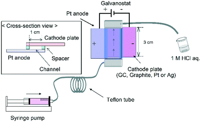
The reactor was constructed from an anode plate (Pt plate, 3.0 cm width, 3.0 cm length) and a cathode plate (GC, graphite, Pt or Ag plate, 3.0 cm width, 3.0 cm length) (Fig. 2). A spacer (20–110 μm thickness double faced adhesive tape) was used to leave a rectangular channel exposed and the two electrodes were simply sandwiched together (area of the two electrodes: 1.0 × 3.0 cm2). After connecting Teflon tubing to the inlet and outlet the reactor was sealed with epoxy resin.2.3. General procedure for electrochemical carboxylation
2.4. Linear sweep voltammetry
Linear sweep voltammetry experiments were performed using an undivided cell equipped with a working electrode (GC, graphite, Pt or Ag disk electrode, 3.0 mm ϕ), an auxiliary electrode (2.0 × 2.0 cm2, Pt plate) and a reference electrode (Ag wire). The ferrocene/ferrocenium couple (Fc/Fc+) was also measured in the same electrochemical system and the electrode potential was reported as values referred to the apparent standard potential of the system (Fig. S1 in ESI†).3. Results and discussion
First, the model carboxylation reaction was carried out using a conventional batch-type reactor and a flow microreactor (Table 1). With a batch-type reactor, the use of a sacrificial Mg anode gave α-amino acid 1a in a reasonable yield (Table 1, entry 1) which can be ascribed to the Mg ions generated from the anode stabilizing the unstable intermediate anion C as mentioned above. In contrast, the yield of 1a dramatically decreased due to decomposition of intermediate anion C (Table 1, entry 2). On the other hand, the electrochemical carboxylation using a flow microreactor gave the highest yield of 1a (70%), even without using a sacrificial Mg anode (Table 1, entry 3). In addition, it was found that the remaining 30% could be attributed to unreacted starting imine. These results indicate that unstable intermediate C immediately undergoes acidification in the microreactor before its decomposition. Therefore, it can be stated that the microreactor is extremely useful for the electrochemical synthesis of α-amino acids without the use of sacrificial anodes.| Entry | Reactor type | Cathode | Anode | Yield of 1a (%)e |
|---|---|---|---|---|
| a Experimental conditions: current density, 15 mA cm−2; charge passed, 4.0 F mol−1; solvent, DMF; substrate, 60 mM of 1; supporting electrolyte, 70 mM of Bu4NBF4. b Anode, Mg ribbon (0.32 × 10 cm2); cathode, glassy carbon (GC) plate (1.5 × 2.0 cm2). c Anode, Pt plate (2.0 × 2.0 cm2); cathode, GC plate (1.5 × 2.0 cm2). d Anode, Pt plate (1.0 × 3.0 cm2); cathode, GC plate (1.0 × 3.0 cm2); electrode distance, 20 μm; flow rate, 7.3 mL h−1. e Determined by RP-HPLC. | ||||
| 1 | Batch-type reactorb | GC | Mg | 60 |
| 2 | Batch-type reactorc | GC | Pt | 34 |
| 3 | Flow microreactord | GC | Pt | 70 |
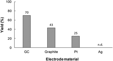
During the next stage of investigations, the effect of the reaction conditions on the yield of 1a synthesized in the flow microreactor was investigated. The cathode material is also an important factor in controlling the efficiency of the electrochemical carboxylation. Therefore, to select suitable cathode materials for the system, electrochemical carboxylation of 1 was conducted using various cathode materials, such as glassy carbon (GC), graphite, platinum (Pt) and silver (Ag). As shown in Fig. 3, the use of the GC electrode led to a higher yield compared to the other cathode materials. In the model electrochemical carboxylation employed in this work, highly reactive radical anion A should be generated predominantly at the cathode, and should then react with CO2 to provide α-amino acid 1a. The cathode material should thus possess a high overpotential for CO2 reduction. In fact, we confirmed by linear sweep voltammetry (LSV) for CO2 reduction that the overpotential for the tested electrodes for CO2 reduction increased in the order: Ag < Pt ≈ graphite < GC (Fig. S1 in ESI†). Therefore, GC seems to be a promising cathode material for electrochemical carboxylation, and the GC electrode was selected as the cathode for this reaction system and used in the following experiments.
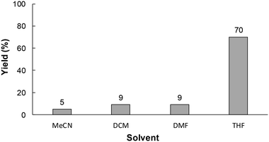
Electrolytic solvents play an important role in the stability of the reaction intermediate in electrochemical syntheses.9 Therefore, the electrochemical carboxylation was preformed using various electrolytic solvents. As shown in Fig. 4, the yield of 1a was strongly influenced by the type of solvent used, and the use of THF as an electrolytic solvent gave the highest yield of 1a. This was attributed to the rate of the reaction between radical anion A, generated by cathodic reduction of 1, and CO2 being accelerated with the use of a smaller accepter number solvent like THF, because the smaller the accepter number of the solvent the fewer interactions there will be with radical anion A (the higher reactivity of radical anion A).
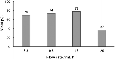
Next, we investigated the effect of flow rate on the yield of 1a. As shown in Fig. 5, the yield of 1a increased with an increase in the flow rate and reached a maximum value (78%) at a flow rate of 15 mL h−1, while it decreased at 29 mL h−1. At slower flow rates, the residence time in the reactor should be longer, and hence unstable anion C would be decomposed before the following acidification. On the other hand, at a flow rate of 15 mL h−1, substrate 1 would be ejected from the electrolysis region before its cathodic reduction under such a high flow rate condition.
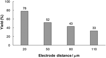
From the above considerations, it can be expected that the residence time of unstable intermediate C in the reactor influences the product yield. In this electrosynthetic flow system, the residence time can also be controlled by changing the electrode distance while the electricity is maintained at the same level. Therefore, we next examined the effect of the electrode distance on the model reaction (Fig. 6). The yield of 1a decreased with an increase in the electrode distance. This result apparently indicates that a longer residence time led to side reactions or decomposition of unstable intermediate C.
Finally, to demonstrate the general applicability of this electrolysis system, electrochemical carboxylation of various imines was investigated (Table 2). It can be expected that the amino acid yield significantly depends on the reactivity of the radical anion intermediates towards CO2, which is determined by their electron structure. In general, the increase in electron density on the carbon atom of the C![[double bond, length as m-dash]](https://www.rsc.org/images/entities/char_e001.gif) N bond enhances the nucleophilic reactivity of the radical anion intermediates. However, contrary to our expectations, the amino acid yields apparently decreased with the introduction of electron-donating groups, such as methyl and methoxy groups, into the imines' benzylidene and aniline fragments (Table 2, entries 2–4). Titov and co-workers reported that the radical anion intermediates with high reactivity underwent dimerization rather than the reaction with CO2 during electrochemical carboxylation.6a,10 In fact, we also detected such dimerization products by NMR analysis in the case with substrate imines 2–4. On the other hand, the introduction of a fluorine atom into the para-position of the imines’ aniline fragment decreased the corresponding amino acid yield (Table 2, entry 5). This can be ascribed to the decrease in electron density on the carbon atom, which diminished its nucleophilic reactivity towards CO2. In order to tune the reactivity of the radical anion intermediate, we employed imine 6 which has both electron-donating (CH3O) and withdrawing (CN) groups. In this case, the amino acid yield improved to some extent.
N bond enhances the nucleophilic reactivity of the radical anion intermediates. However, contrary to our expectations, the amino acid yields apparently decreased with the introduction of electron-donating groups, such as methyl and methoxy groups, into the imines' benzylidene and aniline fragments (Table 2, entries 2–4). Titov and co-workers reported that the radical anion intermediates with high reactivity underwent dimerization rather than the reaction with CO2 during electrochemical carboxylation.6a,10 In fact, we also detected such dimerization products by NMR analysis in the case with substrate imines 2–4. On the other hand, the introduction of a fluorine atom into the para-position of the imines’ aniline fragment decreased the corresponding amino acid yield (Table 2, entry 5). This can be ascribed to the decrease in electron density on the carbon atom, which diminished its nucleophilic reactivity towards CO2. In order to tune the reactivity of the radical anion intermediate, we employed imine 6 which has both electron-donating (CH3O) and withdrawing (CN) groups. In this case, the amino acid yield improved to some extent.
| Entry | Imine | Amino acid | Yield (%) |
|---|---|---|---|
| a Experimental conditions: cathode, GC plate (1.0 × 3.0 cm2); anode, Pt plate (1.0 × 3.0 cm2); current density, 15 mA cm−2; charge passed, 2 F mol−2; solvent, THF; substrate concentration, 60 mM; supporting electrolyte, 70 mM of Bu4NBF4. b Determined by RP-HPLC. c Determined by 1H-NMR (internal standard: nitromethane). | |||
| 1 |
 1
1
|
 1a
1a
|
78b |
| 2 |
 2
2
|
 2a
2a
|
61b |
| 3 |
 3
3
|
 3a
3a
|
n.d.c |
| 4 |
 4
4
|
 4a
4a
|
n.d.c |
| 5 |
 5
5
|
 5a
5a
|
32c |
| 6 |
 6
6
|
 6a
6a
|
41c |
From these generality experiments, it can be stated that this new electrolytic system using a flow microreactor is effective for electrochemical carboxylation of a wide range of imines, except for some substrates which have a strong electron-donating group like a methoxy group.
4. Conclusions
We have developed a novel and green method for α-amino acid synthesis by electrochemical carboxylation of imines using a flow microreactor. This method has the major advantage of not requiring sensitive, expensive or toxic reagents. In addition, the reaction could be conducted using single flow-through operations without the need for sacrificial anodes and under very mild conditions. These promising results provide a method for efficient and environmentally benign α-amino acid syntheses.Conflicts of interest
There are no conflicts to declare.Acknowledgements
This work was financially supported by the Grant-in-Aid for Scientific Research on Innovative Areas (No. 2707: Middle Molecular Strategy).References
- (a) D. S. Mottram, B. L. Wedzicha and A. T. Dodson, Nature, 2002, 419, 448 CrossRef CAS PubMed; (b) M. K. Angele, S. M. Nitsch, R. A. Hatz, P. Angele, T. Hernandez-Richter, M. W. Wichmann, I. H. Chaudry and F. W. Schidberg, Eur. Surg. Res., 2002, 34, 53 CrossRef CAS PubMed; (c) J. Liao, Biotechnol. Prog., 2007, 23, 28 CrossRef CAS PubMed; (d) E. R. Jarvo and S. J. Miller, Tetrahedron, 2002, 58, 2481 CrossRef CAS.
- (a) S. Akabori, S. Sakurai, Y. Izumi and Y. Fujii, Nature, 1956, 178, 323 CrossRef CAS; (b) E. J. Corey, R. J. McCaully and H. S. Sachdev, J. Am. Chem. Soc., 1970, 92, 2476 CrossRef CAS PubMed; (c) C. Nájera and J. M. Sansano, Chem. Rev., 2007, 107, 4584 CrossRef PubMed.
- A. Strecker, Ann. Chem. Pharm., 1850, 75, 27 CrossRef.
- D. Kumar, A. Saini Suresh and J. S. Sandhu, Rasayan J. Chem., 2008, 1, 639 CAS.
- (a) G. Katsoulos and M. Schlosser, Tetrahedron Lett., 1993, 34, 6264 CrossRef; (b) A. A. Sathe, D. R. Hartline and A. T. Radosevich, Chem. Commun., 2013, 49, 5040 RSC; (c) T. Mita, J. Chen, M. Sugawara and Y. Sato, Angew. Chem., Int. Ed., 2011, 50, 1393 CrossRef CAS PubMed; (d) T. Mita, J. Chen and Y. Sato, Org. Lett., 2014, 16, 2200 CrossRef CAS PubMed; (e) T. Mita, K. Michigami and Y. Sato, Org. Lett., 2012, 14, 3462 CrossRef CAS PubMed; (f) T. Mita, M. Sugawara, K. Saito and Y. Sato, Org. Lett., 2014, 16, 3028 CrossRef CAS PubMed; (g) T. Mita, Y. Higuchi and Y. Sato, Chem. – Eur. J., 2013, 19, 1123 CrossRef CAS PubMed.
- (a) V. G. Koshechko, V. E. Titov, V. N. Bondarenko and V. D. Pokhodenko, J. Fluorine Chem., 2008, 129, 701 CrossRef CAS; (b) C. Li, X. Song, L. Tao, Q. Li, J. Xie, M. Peng, L. Pan, C. Jiang, Z. Peng and M. Xu, Tetrahedron, 2014, 70, 1855 CrossRef CAS; (c) D. K. Root and W. H. Smith, J. Electrochem. Soc., 1982, 129, 1231 CrossRef CAS.
- (a) M. Tokuda, J. Nat. Gas Chem., 2006, 15, 275 CrossRef CAS; (b) G. Silvestri, S. Gambino and G. Filardo, Acta Chem. Scand., 1991, 45, 987 CrossRef CAS.
- H. Tateno, Y. Matsumura, K. Nakabayashi, H. Senboku and M. Atobe, RSC Adv., 2015, 5, 98721 RSC.
- (a) R. Yamaguchi, B. Hatano, T. Nakayasu and S. Kozima, Tetrahedron Lett., 1997, 38, 403 CrossRef CAS; (b) J. Yoshida, S. Suga, S. Suzuki, N. Kinomura, A. Yamamoto and K. Fujiwara, J. Am. Chem. Soc., 1999, 121, 9546 CrossRef CAS.
- V. E. Titov, V. N. Bondarenko, V. G. Koshechko and V. D. Pokhodenko, Theor. Exp. Chem., 2008, 44, 271 CrossRef CAS.
Footnote |
| † Electronic supplementary information (ESI) available. See DOI: 10.1039/c7re00149e |
| This journal is © The Royal Society of Chemistry 2017 |

