Synthesis of narrow sized silver nanoparticles in the absence of capping ligands in helical microreactors
Received
8th November 2016
, Accepted 11th January 2017
First published on 11th January 2017
Abstract
This paper demonstrates the critical effect of the curvature of microreactors on the size distribution of silver nanoparticles during their continuous synthesis in the absence of capping ligands. By a combination of experimental data and deep understanding of the fluid dynamics inside the reactor, we demonstrate that decreasing the helix diameter of the reactor promotes the onset of transversal flows and radial mixing in helical reactors. These secondary flows enable fast nucleation and homogeneous growth during the synthesis leading to a delicate control of the particle size distribution. A similar effect is achieved by increasing the total flow rate, assuming that the Dean number is above ∼5, while no effect of the pitch distance within the experimental range on the size distribution is observed. These results will directly impact the nanomaterial field and the development of manufacturing routes as the size of the nanoparticles is known to play a key role in determining their chemical and physical properties.
Introduction
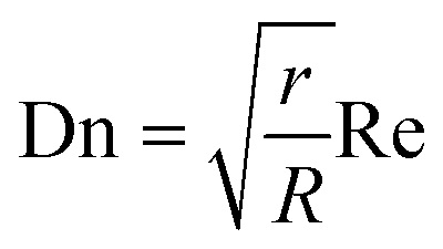
Metal nanoparticles have stimulated the interest of the scientific community during the past decades due to their unique catalytic,1–3 optical,4 electronic,5 magnetic,6etc. characteristics. These intrinsic chemical and physical properties are strongly dependent on the size and shape of the metal nanoparticles7,8 with a huge scientific effort dedicated to the development of reproducible and reliable synthetic routes. A number of liquid phase routes such as reduction methods have been developed9 with a high size control in the presence of organic capping agents such as poly(N-vinyl-2-pyrrolidone) (PVP),10 surfactants such as cetyltrimethylammonium bromide (CTAB)11 and polymeric materials such as sodium polyacrylate12 amongst many others. Efficient mixing of metal precursors, reducing agents and capping ligands as well as synthesis conditions are known to be of key importance in the resulting particle size distribution.9 Within this context, microscale continuous flow reactors have been presented as a production tool for nanoparticles due to their unrivaled heat and mass transfer advantages.13 The literature offers elegant examples of size-controlled synthesis of metal nanoparticles from the pioneering work on monometallic systems such as gold14 and silver15 nanoparticles to well-defined bi-metallic systems.16 In the past decade, most of the progress in the field has been focused on parameter optimization to obtain narrow size dispersity by narrowing the residence time distribution of microdevices. In this way, one can minimize the difference between the growth of nanoparticles formed close to the center of the channel (where the velocity reaches its maximum value) and that of nanoparticles formed close to the reactor's walls. The most significant work in this area includes the use of segmented flow17 and bubbles18 to promote internal recirculation of the fluid, the use of spinning disk reactors to enhance mixing inside the channels19 as well as a number of static mixer configurations used as reactors including pinch points,20 T-shaped mixers,21 serpentine channels,22 and co-axial mixers.23 All these strategies to narrow the particle size distribution in microdevices by enhancing micromixing rely on the use of capping ligands that not only facilitate the size control of nanoparticles but also avoid their random growth due to agglomeration. However, despite the effectiveness of the capping ligands from a synthetic point of view, they have been shown to interfere with the final applications of the nanoparticles. The interaction of the capping ligands with the nanoparticles' surface can form a physical diffusional or electronic barrier24 in catalysis and denaturing enzymes in bio-related applications25 to give a few examples. In addition, Jain et al.26 reported that removal of capping molecules (protein shell) from the surface of silver nanoparticles showed a significant increase in their antibacterial activity against both Gram-positive and Gram-negative bacterial species. Post-synthesis removal of the capping ligands typically involve thermal or oxidative treatments which normally lead to particle agglomeration. Facile methods for post-synthesis removal of capping ligands including washing27 or stripping28 have been developed during the past few years with different levels of success. Alternatively, our strategy consists of the total negation of the use of organic capping ligands during the synthesis of nanoparticles by maximizing the laminar flow environment in microdevices to avoid the agglomeration of particles. After the synthesis, particles can then be stabilized using the most appropriate method aligned to their final applications, e.g. by using supports in heterogeneous catalysis.29,30 In this paper, we demonstrate the synthesis of narrow sized silver nanoparticles by narrowing the residence time distribution and promoting radial mixing by modifying the reactor geometry. In this context, Newtonian flows in curved reactor geometries, such as helical channels, have been widely studied in the past and used in a number of applications.31 William Dean was the first to develop an analytical solution for fully developed laminar flow in curved tubes32 and quantify the reduction in flow due to curvature by what is now called the dimensionless Dean number:| |  | (1) |
where r is the inner radius of the tube, R is the radius of the helix and Re is the Reynolds number.
Using a combination of experimental data and fluid dynamic simulations, this paper reports the synthesis of silver nanoparticles in helical reactors in the absence of capping ligands, investigating the effect of curvature and torsion as well as the effect of flow rate on the final silver particle size and polydispersity. We show that micromixing enhanced by secondary flows in helical reactors plays a more critical role in particle dispersity than narrow residence time distributions due to the promotion of fast nucleation and homogeneous growth under laminar flow where mixing is largely mediated by molecular diffusion.
Experimental section
Reagents and chemicals used in this work, including silver nitrate solution (0.1 M), sodium borohydride solution (12 wt% in 14 M NaOH), and bovine serum albumin (BSA), were all purchased from Sigma-Aldrich and used without further purification. Ultrapure water used to prepare the solutions was obtained using an ELGA Maxima ultra-pure water system (18.2 MΩ cm resistivity).
Synthesis of silver nanoparticles in helical reactors
Silver nanoparticles were synthesized in perfluoroalkoxy (PFA, IDEX Health & Science LLC) helical tubular reactors with an inner diameter of 0.762 mm and an outer diameter of 1.5875 mm. The reactors were constructed using PFA tubing and 3D-printed support (printed using a Form 1+ stereolithography printer from FormLabs) to provide a precise control of all the reactor parameters, such as helix diameter, pitch distance, and tubing length. In a typical synthesis, freshly prepared silver nitrate solution (0.1 mM) and sodium borohydride solution (0.6 mM) were introduced into the helical reactor using syringe pumps (Pump 11 Elite, Harvard Apparatus) with a fixed flow rate ratio, QAgNO3![[thin space (1/6-em)]](https://www.rsc.org/images/entities/char_2009.gif) :QNaBH4= 1:1, at 60 °C using a T mixer (ETFE, 0.508 mm through hole, 2.9 μL swept volume, IDEX Health & Science LLC). A large excess of NaBH4 with a molar ratio of 1:6 was used in all cases to avoid any changes in the reduction kinetics due to NaBH4 potential hydrolysis. An IKA RCT basic stirrer hotplate equipped with an IKA ETS-D5 temperature controller (uncertainty of ±0.1 K) and a continuously stirred water bath were used to control the reaction temperature by immersing the reactors. The reaction time was controlled by adjusting the total flow rate and tubing length. The outlet of the reactor was introduced into an ice cold solution initially containing pure water to reduce the mobility and consequent agglomeration of the particles post-synthesis. Fig. 1 shows a schematic of the reactor system. To eliminate the contribution of outside UV-radiation in the reaction kinetics, the whole system is kept in the dark during the synthesis process. No silver layer was observed with the naked eye in the inner wall of the tubing.
:QNaBH4= 1:1, at 60 °C using a T mixer (ETFE, 0.508 mm through hole, 2.9 μL swept volume, IDEX Health & Science LLC). A large excess of NaBH4 with a molar ratio of 1:6 was used in all cases to avoid any changes in the reduction kinetics due to NaBH4 potential hydrolysis. An IKA RCT basic stirrer hotplate equipped with an IKA ETS-D5 temperature controller (uncertainty of ±0.1 K) and a continuously stirred water bath were used to control the reaction temperature by immersing the reactors. The reaction time was controlled by adjusting the total flow rate and tubing length. The outlet of the reactor was introduced into an ice cold solution initially containing pure water to reduce the mobility and consequent agglomeration of the particles post-synthesis. Fig. 1 shows a schematic of the reactor system. To eliminate the contribution of outside UV-radiation in the reaction kinetics, the whole system is kept in the dark during the synthesis process. No silver layer was observed with the naked eye in the inner wall of the tubing.
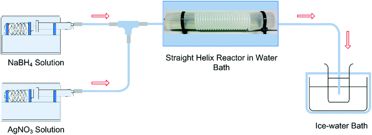 |
| | Fig. 1 Schematic diagram of the experimental setup. | |
Characterization of silver nanoparticles
The extinction spectra of silver nanoparticle solutions were recorded using an Agilent Cary 60 ultraviolet-visible (UV-vis) spectrophotometer. Transmission electron microscopy (TEM) images were obtained using a FEI Tecnai 20 transmission electron microscope. Due to the absence of capping ligands during the synthesis of silver nanoparticles, specimens for TEM analysis were prepared according to Michen et al.'s protocol33 to avoid post-synthesis agglomeration. 0.3 g ml−1 BSA solution was mixed with the silver nanoparticle solution in a 1:1 ratio and the mixture was then kept in an ice-water bath for at least 2 hours before preparing the TEM grid. A 5 μL mixture droplet was then dripped onto the carbon coated copper grid and then naturally dried for over 2 hours. The TEM images were analyzed using an image processing software, ImageJ, to obtain the area-equivalent diameter of the nanoparticles. The measurement uncertainty due to the image resolution is about 2% (∼0.1 nm per pixel per 5 nm).
Computational fluid dynamic simulations
The numerical simulation of the flow in the different reactors was performed using ANSYS-Fluent (ANSYS, R16.0). The computational meshes were generated in ICEM CFD, with the total grid numbers ranging from 5000000 to 7000000 depending on the geometry. A representative geometry and a cross section mesh of the channel are shown in Fig. 2. In this study, the stopping criterion for residual convergence was set to 1 × 10⁻⁷ due to the complexity of the geometry. The converged solution to steady state fluid flow was used to calculate velocity profiles in three orthogonal directions. Residence time distribution was calculated using a discrete phase model (DPM) where a tracer fluid represented by a large number of discrete massless particles was introduced into a fully developed flow followed by Lagrangian particle tracking analysis to obtain a histogram of the number of particles as a function of time. A proportional injection method where the number of particles in each injection point is proportional to the velocity magnitude at that point was adopted in this work. The model was validated against the known numerical solution for Hagen–Poiseuille flow in straight tubes. The total particle number is larger than 700000 in order to achieve a statistically significant sampling.
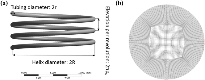 |
| | Fig. 2 (a) A typical helical tube geometry and (b) a cross section mesh of the channel. | |
Results and discussion
Effect of tubing length on particle size distribution in the absence of capping ligands
Silver nanoparticles were synthesized by reduction of silver nitrate by sodium borohydride at 60 °C in the absence of organic capping ligands. Initially, a series of helical reactors with constant curvature and torsion, (constant helix diameter of 14 mm and helix pitch of 1/π mm) and varying lengths (60, 95 and 130 cm) were used to investigate the effect of residence time on the degree of reduction of silver within the reactor boundaries and the particle size and polydispersity. In all cases, a constant total flow rate of 0.7 mL min−1 was used with an AgNO3/NaBH4 molar ratio of 1:6, with the relative concentration of NaBH4 well in excess to achieve full reduction of the silver precursor.35
The formation of silver nanoparticles involves the sodium borohydride reduction of silver nitrate under basic conditions:
| 8Ag+ + BH4− + 8OH− → 8Ag0 + H2BO3− + 5H2O |
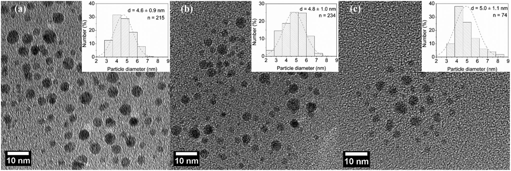
Under acidic conditions, sodium borohydride reacts slowly with water ultimately to liberate 4 moles of hydrogen per mole of the compound; however, in our case, highly basic conditions reduce the formation of hydrogen gas which ensures a single-phase system in the microreactor and also helps improve the stability of the nanoparticle colloid solution. Generally speaking, the formation of silver nanoparticles in a microreactor follows the LaMer mechanism.34 AgNO3 solution and NaBH4 solution were mixed in a T-mixer where the reduction and nucleation start. Following nucleation, particle growth proceeds in the microtube mainly by addition of the monomer to the particle surface, and particle growth due to coalescence is minimized due to the laminar flow in the microtube and the presence of BH4− which acts as an electrostatic stabilizer. Fig. 3 shows representative TEM images of silver nanoparticles and their corresponding particle size distribution. Similar average diameter and standard distribution values of 4.6 ± 0.9 nm, 4.8 ± 1.0 nm and 5.0 ± 1.1 nm were observed for 60, 95 and 130 cm reactors' lengths corresponding to residence times of 23, 37 and 50 s, respectively.
 |
| | Fig. 3 TEM images and particle size distributions of AgNPs synthesized in helical tubular microreactors with lengths of (a) 60 cm, (b) 95 cm, and (c) 130 cm. Conditions: helix diameter: 14 mm, helix pitch: 1/π mm, and total flow rate: 0.7 mL min−1 with an AgNO3/NaBH4 molar ratio of 1:6. | |
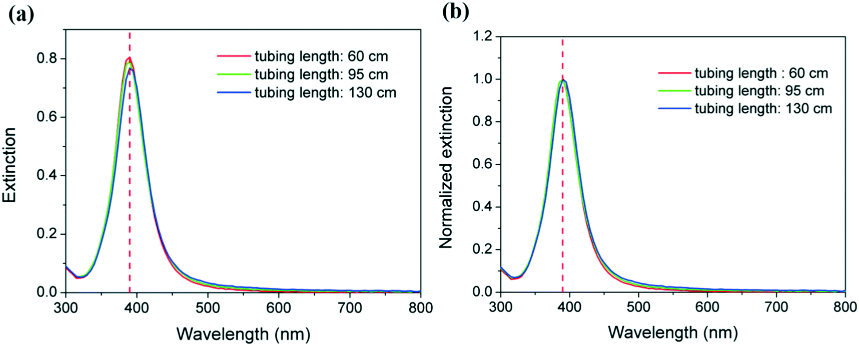
These observations are in agreement with the similarities of their corresponding UV-vis spectra as shown in Fig. 4a. In all cases, maximum absorbance is observed at 390 nm, with no perceptible shifts as the reactor residence time increases. Even more importantly, the same amount of reduced silver is present in all the samples as demonstrated by the overlap of the spectra which suggests full reduction of the silver ions even at a residence time of 23 s (corresponding to a microreactor length of 60 cm). This is in agreement with the kinetic studies of silver reduction under similar conditions previously reported in the literature where reduction is observed to occur within hundreds of ms.36,37 The overlap of the normalized spectra in Fig. 4b and similar full width at half maximum (FWMH) values for the three samples support the similar size dispersity in all cases as demonstrated by TEM. As the length of the reactor increases from 60 to 130 cm, there is a very small but quantifiable increase in the overall average particle size from 4.6 to 5.0 nm. The increase is also accompanied by a minute broadening of the size distribution from 0.9 to 1.1 nm. Although the differences among these values fall within the associated standard deviation, a trend as a function of length of the reactor is shown. This observation suggests that the growth of particles by Ostwald ripening increases with the length of the reactor, and consequently, the residence time increases, despite its rate being very slow under the studied conditions.
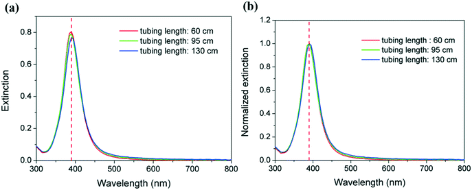 |
| | Fig. 4 (a) UV-vis extinction spectra and (b) normalized extinction spectra for AgNPs synthesized in helical tubular microreactors with different tubing lengths. Conditions: helix diameter: 14 mm, helix pitch: 1/π mm, and total flow rate: 0.7 mL min−1 with an AgNO3/NaBH4 molar ratio of 1:6. | |
Full reduction conversion of silver within the reactor boundaries is essential to demonstrate the effect of the geometric parameters of helical reactors on the agglomeration of metal nanoparticles during their synthesis in the absence of organic capping ligands. In this manner, artifacts associated with non-homogeneous metal reduction occurring in the droplets formed at the outlet of the reactor can be fully avoided.38 Such droplets are known to have internal recirculation flow patterns which also promote agglomeration. To reduce this phenomenon to its minimum, in this case, the outlet of the reactor was introduced into an ice-cold solution to avoid droplet formation, quench any further reaction and reduce particle mobility.
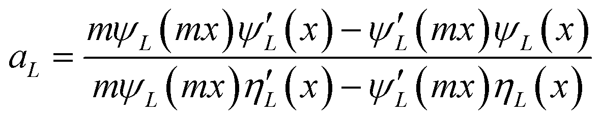
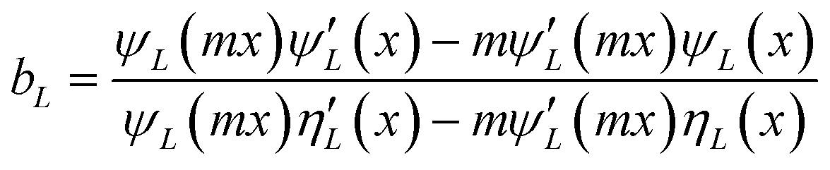
As explained in the experimental section, the absence of organic capping ligands during these syntheses considerably complicates the imaging of the particles. Under these conditions, it is necessary to stabilize particles post-synthesis to avoid the onset of drying artifacts and post-synthesis agglomeration and thereby allowing the preservation of the in situ colloidal features of the nanoparticles to be observed by microscopy. In this work, we have followed a previously reported stabilization protocol using a bovine serum albumin protein solution.33 Alternatively, and to avoid any unforeseeable post-synthesis agglomeration to interfere with the conclusions of this work, we propose the Mie model as a predictive tool for particle size distribution by fitting the UV-vis spectra obtained immediately after the nanoparticle synthesis. Mie theory is a well-established and documented solution of the electromagnetic Maxwell's equations describing the scattering of an electromagnetic plane wave by a homogeneous sphere.39 It has previously been successfully applied to estimate the average particle size of gold nanoparticles in solutions.40 The input parameters are the particle size and the optical functions of the particle material and the surrounding medium. The extinction cross section is calculated from Mie theory for particles with radius R:
| | 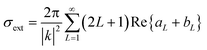 | (2) |
where the function Re gives the real part of the complex number
aL +
bL,
| | 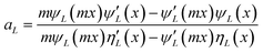 | (3) |
| | 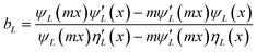 | (4) |
where
m =
n/
nm,
n denotes the complex index of refraction of the particle and
nm denotes the real index of refraction of the surrounding medium.
k is the wave vector,
x = |
k|
R, and
R is the size parameter.
ψL(
z) and
ηL(
z) are the Riccati–Bessel cylindrical functions. The summation index
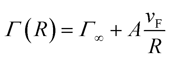
L gives the order of the partial wave, and in this work, it was set to be 3. The dielectric constant can be corrected as a function of particle size by introduction of the following relationship:
39| |  | (5) |
where
Γ∞ is the bulk metal value, which is 3.23 × 10
13 s
−1 for silver, and
vF is the Fermi speed, which is 1.39 × 10
6 m s
−1 for silver.
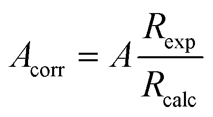
A is an empirical parameter which needs to be corrected by correlating the particle radius from TEM images and the calculated particle radius when
A = 1. The agreement between particle size distribution calculated by TEM in
Fig. 3 for the silver particles synthesized at different residence times and the overlap of their respective UV-vis spectra in
Fig. 4 has allowed us to correct the parameter
A based on the model previously validated and published by Amendola
et al.40 for a gold system:
| |  | (6) |
where
Rexp is the radius measured by TEM images, and
Rcalc is the radius calculated using Mie theory model with
A = 1.
Fig. 5 shows the relationship between the radii obtained by TEM images and parameter
A values; thus, an empirical equation can be proposed:
| | | A = − 0.5495 + 0.6905R | (7) |
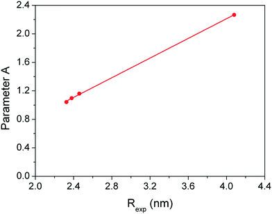 |
| | Fig. 5 The relationship between the radii obtained by TEM images and the empirical parameter A values used in the Mie model. | |
where
A is the corrected parameter which will be used in
eqn (5), and
R is the radius of the nanoparticles. This equation was adopted for all the Mie fittings discussed below.
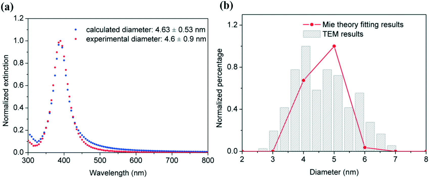
In this way, a MATLAB code available at the University of Cambridge open data repository (http://dx.doi.org/10.17863/CAM.6226) allows the prediction of particle size distribution from the UV-vis spectra. The validation of this method is demonstrated in Fig. 6 by the overlap of the experimental UV-vis spectra and TEM particle size distribution and the estimated ones using the described Mie model. The differences are associated with the use of a lognormal distribution by the Mie model which not always aligns with the experimental observations. Despite this, this approach of using Mie theory as a predictive size distribution tool allows fast and real-time monitoring of metal nanoparticles.
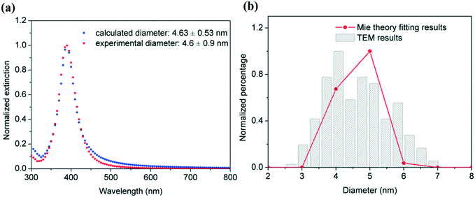 |
| | Fig. 6 (a) Comparison of the experimental UV-vis spectra of silver nanoparticles synthesized in helical tubular microreactors (length: 60 cm, helix diameter: 14 mm and helix pitch: 1/π mm, total flow rate: 0.7 mL min−1 with an AgNO3/NaBH4 molar ratio of 1:6) and the predicted one using the Mie model. (b) Comparison of particle diameter distributions obtained from the Mie model and TEM images. | |
Effect of helical reactor geometry on particle size distribution in the absence of capping ligands
To demonstrate the effect of the geometry of helical rectors for the synthesis of silver nanoparticles in the absence of organic capping ligands on the resulting size control, a series of helical reactors were built with the aid of stereolithography 3D printing tools with varying helix diameters and pitch distances in order to vary the dimensionless curvature and torsion as defined in eqn (8) and (9).| |  | (8) |
| |  | (9) |
where r is the inner radius of the tube, R is the radius of the helix and ps is the pitch distance (vertical distance per radian).
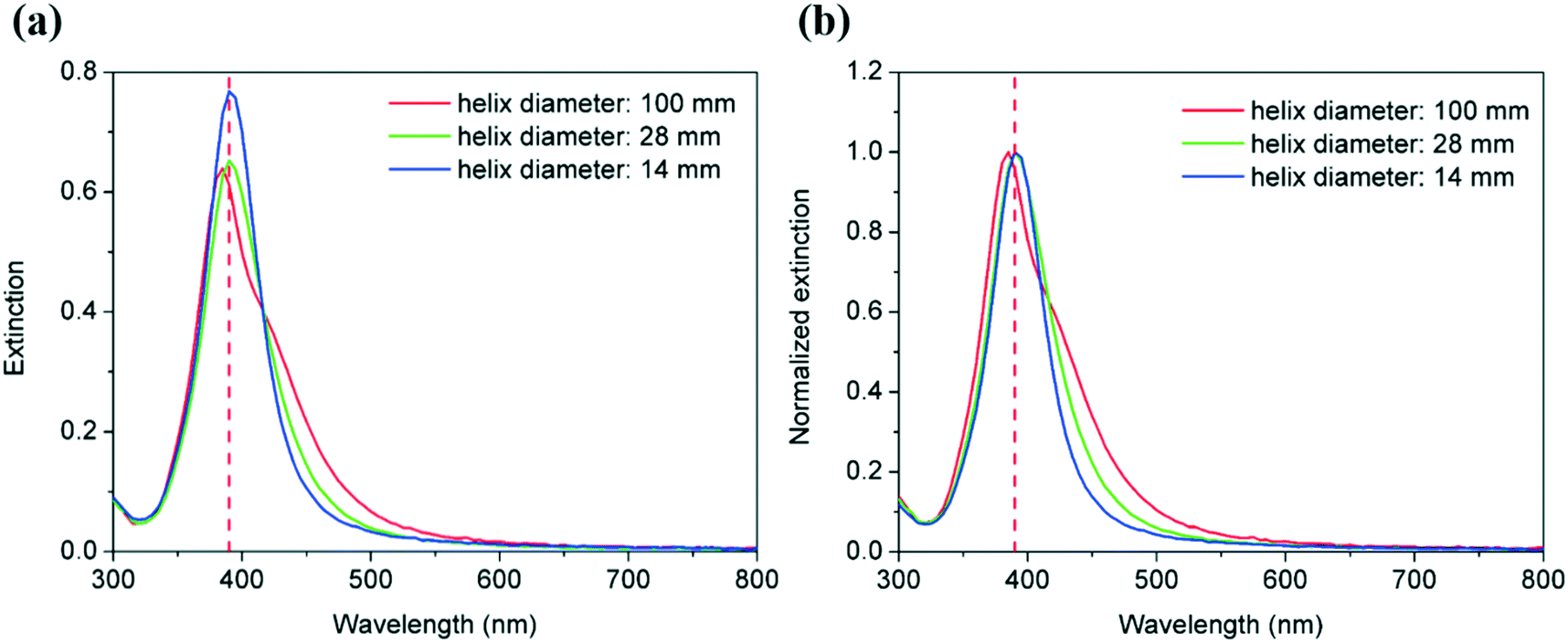
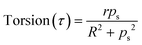
Firstly, silver nanoparticles were synthesised in helical reactors with helix diameters of 14, 28 and 100 mm. The tubing length and pitch distance were fixed as 130 cm and 1/π mm, respectively, and the total flow rate was 0.7 mL min−1. The UV-vis spectra of the corresponding silver nanoparticle suspension are shown in Fig. 7, and it can be seen that as the helix diameter increases from 14 mm to 100 mm, the peak absorbance of the spectra decreases from 0.768 to 0.639 a.u. due to the presence of larger particles in the former case. In agreement with this, the FWHM values increases from 49.8 to 70.6 nm as the helix diameter increases suggesting the broadening of particle size distribution as the curvature of the reactor decreases.
 |
| | Fig. 7 UV-vis extinction spectra (a) and normalized extinction spectra (b) for AgNPs synthesized in helical tubular microreactors with different helix diameters. Conditions: helix length: 130 cm, helix pitch: 1/π mm, and total flow rate: 0.7 mL min−1 with an AgNO3/NaBH4 molar ratio of 1:6. | |
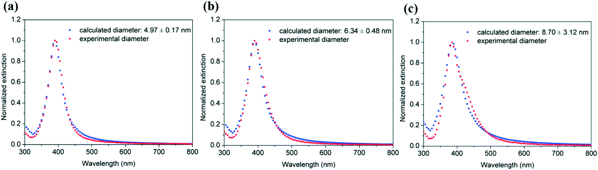
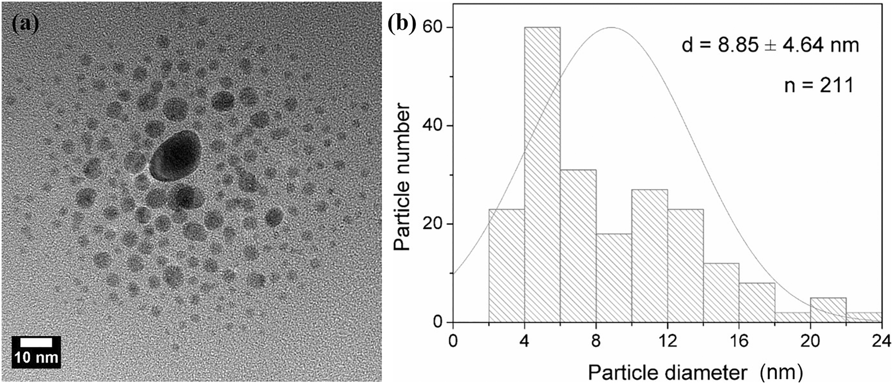
Mie theory was used to predict the particle size and size distribution by fitting the corresponding UV-vis spectra of the silver particle solutions as explained above (Fig. 8). The average particle size and polydispersity values increase from 4.97 ± 0.17 nm, 6.34 ± 0.48 nm to 8.70 ± 3.12 nm as the helix diameter of the microreactor increases from 14 mm, 28 mm to 100 mm, respectively. The size distribution estimated using the Mie theory model of the silver nanoparticles synthesized in the microreactor with 100 mm helix diameter was further verified using TEM measurements (Fig. 9) to test the prediction capability of this model as the particle size value lies out of the range of eqn (7). A good agreement was found between the calculated results (8.70 ± 3.12 nm) and TEM results (8.85 ± 4.64 nm).
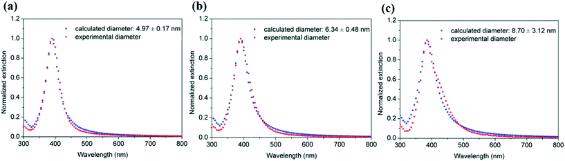 |
| | Fig. 8 Fitting of the experimental UV-vis spectra of AgNPs synthesized in helical tubular microreactors with varying helix diameters of (a) 14 mm, (b) 28 mm and (c) 100 mm using the Mie model. Conditions: reactor length: 130 cm, helix pitch: 1/π mm and total flow rate: 0.7 mL min−1 with an AgNO3/NaBH4 molar ratio of 1:6. | |
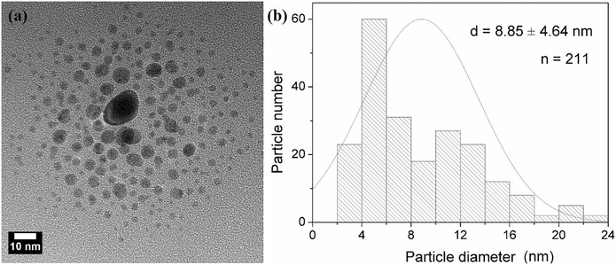 |
| | Fig. 9 (a) TEM images and (b) particle size distributions of AgNPs synthesized in helical tubular microreactors with a length of 130 cm, a helix diameter of 100 mm and a helix pitch of 1/π mm. | |
It is important to note here that the reactor with the bigger helix diameter of 100 mm was intended to simulate, from a practical point of view, a straight reactor where it can be observed that a considerably broader particle size distribution is achieved as well as a larger average particle size. Both parameters are greatly affected by the promotion of radial mixing achieved in helical reactors with respect to their straight channel counterparts due to two contributing factors: (i) their narrower residence time distribution and (ii) faster nucleation rates and homogeneous growth promoted by effective micromixing as explained below.
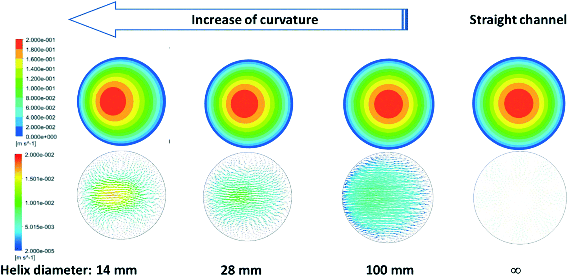
Understanding these observations requires careful consideration of the complex fluid dynamics occurring inside helical channels. The curvature of the channels generates secondary flows to maintain the momentum balance between the centrifugal force produced by the curvature of the system and the consequent pressure gradient parallel to the axis of symmetry.31 Insights into the fluid dynamics and the magnitude of these secondary flows in our helical reactors were possible by linking our experimental data with computer fluid dynamic simulations using ANSYS-fluent. The characteristic parabolic velocity profile of straight channels under laminar flow is depicted in Fig. 10 by the cross section symmetric velocity magnitude contour. By increasing the curvature of the reactor, the velocity profile of is not only shifted outwards the center of the curvature but also the maximum velocity value slightly decreases. The reactor curvature affects the flow pattern by the onset of secondary flows where fluid elements move from the wall's proximities towards the inner part of the channel along the upper and lower halves of the channel creating Dean vortices which greatly enhance the radial mixing in the channel. As shown in Fig. 10, the magnitude of such secondary flows decreases as the curvature of the helical reactors decreases, being inexistent in conventional straight reactors.
 |
| | Fig. 10 Fluid dynamic simulation results of the effect of helix diameter on the formation of secondary transverse flows with an inlet velocity of 0.1 m s−1. The upper row shows the cross section velocity magnitude contour and the bottom row shows the corresponding cross section velocity vectors. | |
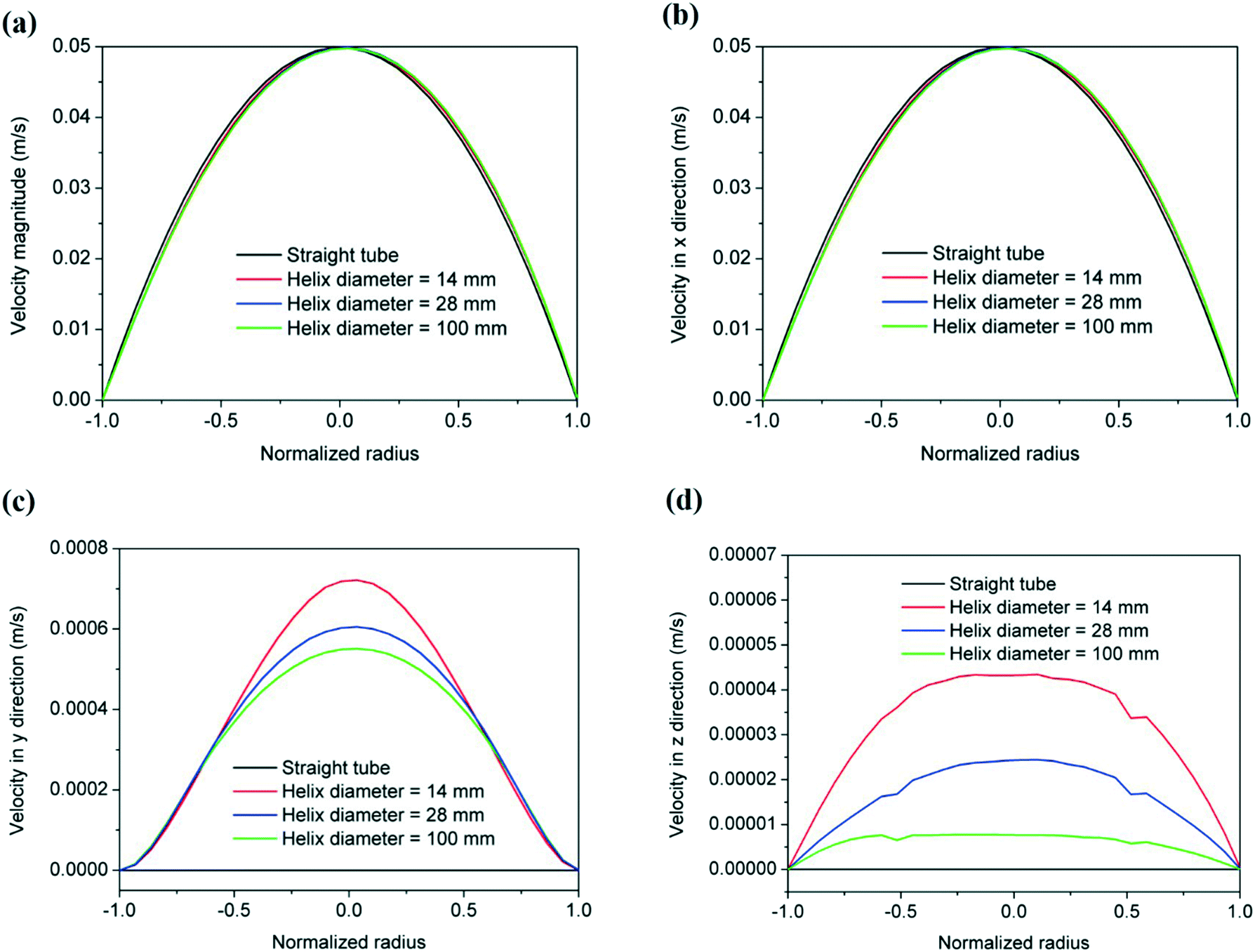
Quantification of the velocities in the three orthogonal directions under experimental conditions was carried out using fluid dynamic simulations (Fig. 11). One should note that the radial velocity (vy) is two orders of magnitude lower than the axial velocity (vx) while vz (three orders of magnitude smaller) represents the velocity at a given radial distance due to the formation of fluid vortices, minimizing the effect of stagnant fluid close to the reactor's wall. As the mixing increases in the radial plane (vy and vz) due to the appearance of secondary flows promoted by an increase in curvature, the nucleation rate increases when strong reducing agents (such as NaBH4) are used,41 leading to narrower particle size distributions as observed herein. A further increase in the reactor curvature is expected to magnify this effect to an optimum point above which mixing in the radial plane starts promoting the agglomeration of the particles due to the absence of capping ligands. This optimum point is therefore believed to be dependent on the concentration of nanoparticles in the reactor.
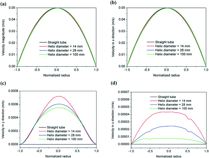 |
| | Fig. 11 Fluid dynamic simulation velocity profiles: (a) velocity magnitude, (b) velocity in the x direction, (c) velocity in the y direction and (d) velocity in the z direction of the helical reactors as a function of helical diameter (pitch: 1/π mm, flow rate: 0.7 mL min−1). The profile of the equivalent straight reactor is shown for comparison. | |
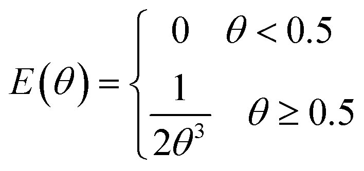
In consequence, the secondary flows promoted by the curvature of the reactor are also expected to affect the residence time distribution. Fig. 12 shows the comparison of the dimensionless form of the residence time distribution function of a straight and a helical reactor with a diameter of 14 mm calculated by dynamic simulations. The residence time distribution function of the straight channel is in agreement with the Hagen–Poiseuille flow numerical solution:42
| | 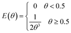 | (10) |
where
θ =
t/
τ,
t is the measured time,
τ is the mean residence time, and
E(
θ) is the normalized residence time distribution function. To achieve these results, a proportional injection method was employed where the number of particles injected at each point was proportional to the velocity magnitude at the point.
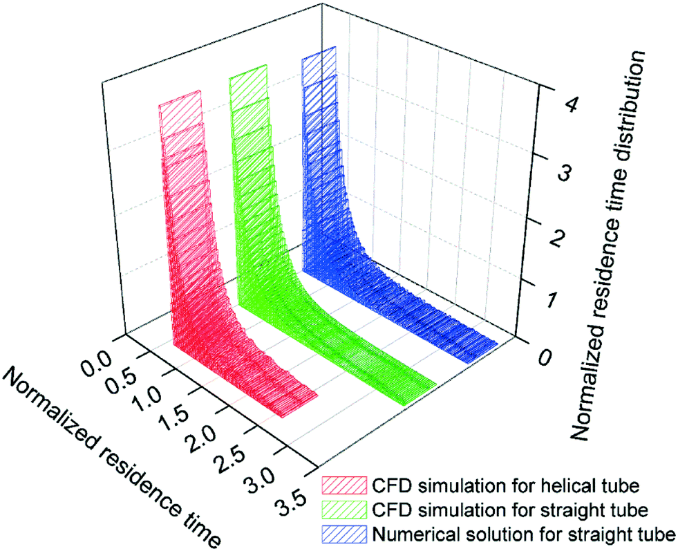
43 This method was programmed in MATLAB and integrated in ANSYS Fluent. Since the flow is steady and fully developed before particle injection, the normalized residence time distribution of a laminar flow is independent of the channel length.
Fig. 12 shows a considerably narrower residence time distribution in the helical reactor compared to the equivalent straight reactor. Additionally, the appearance of the first particles at the outlet of the reactor is slightly delayed in helical reactors compared to straight ones as the mean velocity value slightly decreases as discussed above. This will consequently narrow the particle size distribution of the silver nanoparticles, as observed experimentally. However, negligible changes in residence time distribution are observed as the curvature of the helix is varied within the experimental range studied herein suggesting that the effect of secondary flows in promoting the mixing and consequently fast nucleation (as discussed above) is the dominating factor to achieve a narrow particle size distribution.
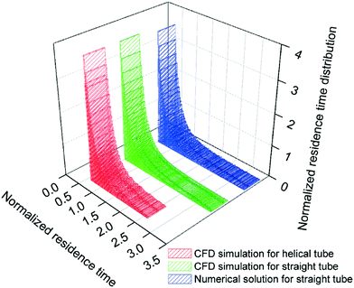 |
| | Fig. 12 Comparison of the dimensionless residence time distribution function in a straight and a helical reactor with a helix diameter of 14 mm. | |
Similarly to the helix diameter of the reactor, the effect of the pitch distance was investigated. For this, three different helical reactors were built with pitch distances of 1/π, 2.5/π, and 5/π mm. In all cases, the reactor length and helix diameter were fixed as 60 cm and 14 mm, respectively. To provide context, one should note that the pitch distance of a straight reactor is infinite, while in a toroidal tube, the pitch distance is zero. The synthesis of silver nanoparticles was carried out in all the systems under the same conditions as above (total flow rate of 0.7 mL min−1, AgNO3/NaBH4 molar ratio of 1:6, 60 °C). The corresponding UV-vis spectra of the silver nanoparticle solutions are shown in Fig. 13. It can be observed that the peak absorbance decreases slightly with an increase in pitch distance; however, the FWHM values do not change significantly ranging from 48.9 to 49.6 nm when the pitch distance is increased from 1/π to 5/π mm.
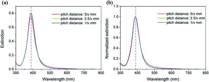 |
| | Fig. 13 (a) UV-vis extinction spectra and (b) normalized extinction spectra for AgNPs synthesized in helical tubular microreactors with different pitch distances. Conditions: reactor length: 60 cm, helix diameter: 14 mm, and total flow rate: 0.7 mL min−1 with an AgNO3/NaBH4 molar ratio of 1:6. | |
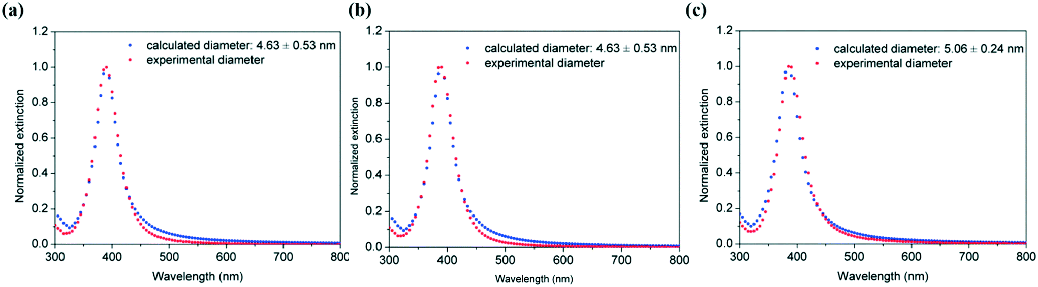
Their corresponding particle size distribution by fitting the UV-vis spectra using the Mie model also shows the similitudes between average particle size and polydispersity obtained with different pitch distances (Fig. 14). Thus, silver nanoparticles with sizes of 4.63 ± 0.53 nm, 4.63 ± 0.53 nm and 5.06 ± 0.24 nm (as estimated from Mie theory) were obtained in the absence of capping ligands in helical reactors with pitch distances of 1/π, 2.5/π, and 5/π mm, respectively. These observations suggest that the pitch distance in helical reactors has a negligible effect on the resulting particle size distribution in the studied experimental range.
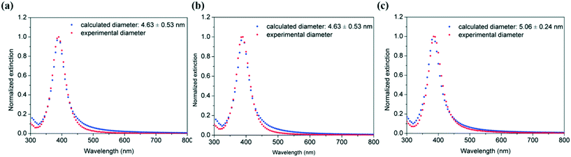 |
| | Fig. 14 Comparison of experimental UV-vis spectra of Ag NPs synthesized in helical tubular microreactors with varying helix pitch values of (a) 1/π mm, (b) 2.5/π mm and (c) 5/π mm, a length of 60 cm, a helix diameter of 14 mm and a total flow rate of 0.7 mL min−1 with an AgNO3/NaBH4 molar ratio of 1:6 and the predicted ones using the Mie model. | |
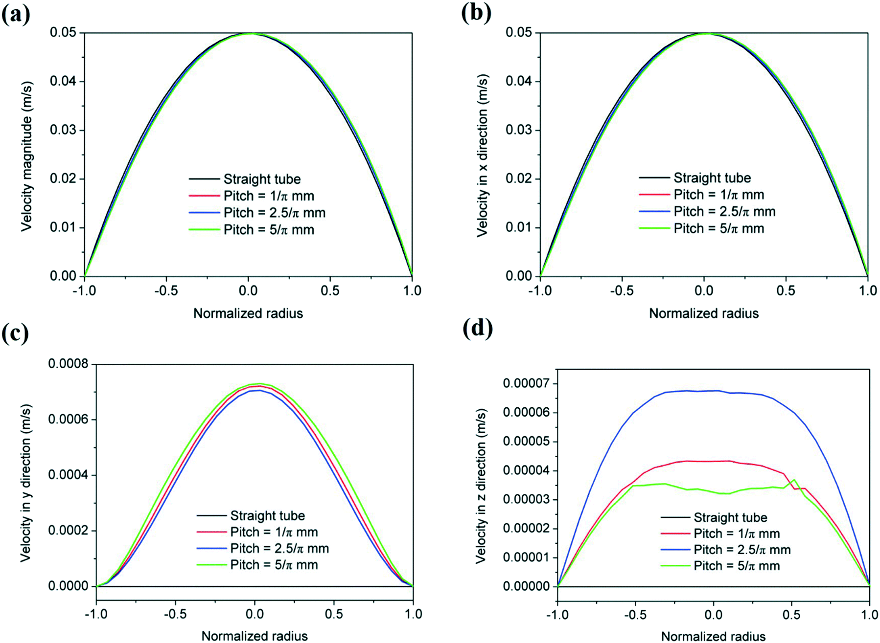
Varying the pitch distance in the helical reactors has a very small effect on the magnitude of the radial velocity (vy) as shown by fluid dynamic simulations in ANSYS (Fig. 15). Additionally, as the torsion increases with increasing pith distance, the vortex circulation (vz) slightly increases, as the friction factor increases. Further increases of the pitch distance decrease the magnitude of vz approximating that of a straight tube.44 These results show a similar radial mixing achieved in the range of pitch distances studied herein, leading to negligible changes in the resulting silver particle size distribution.
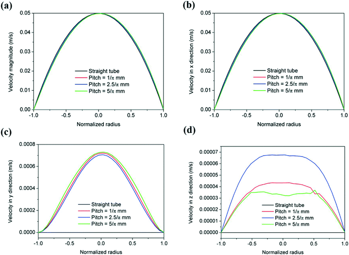 |
| | Fig. 15 Fluid dynamic simulation velocity profiles: (a) velocity magnitude, (b) velocity in the x direction, (c) velocity in the y direction and (d) velocity in the z direction of the helical reactors as a function of pitch distance (helix diameter: 14 mm, flow rate: 0.7 mL min−1). The profile of the equivalent straight reactor is shown for comparison. | |
Effect of total flow rate on particle size distribution in the absence of capping ligands
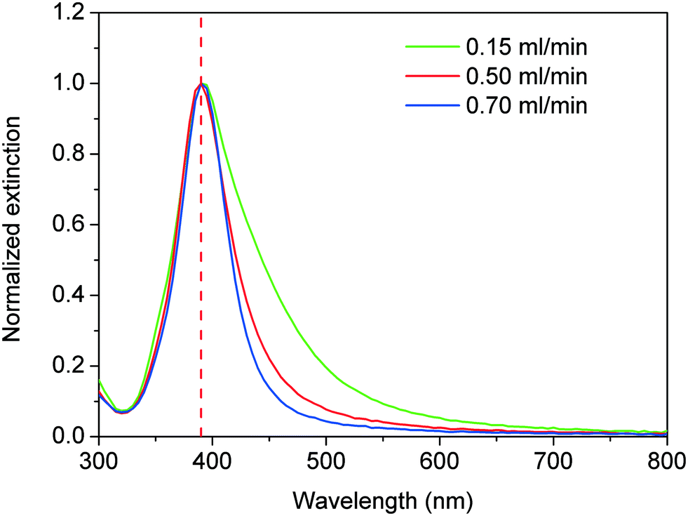
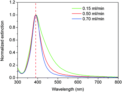
Radial mixing in helical reactors can also be promoted by increasing the fluid velocity (by increasing the Dean number). To investigate the effect of the fluid velocity on the size and polydispersity of silver nanoparticles synthesized in the absence of capping ligands, a series of reactions were carried out in a helical reactor of 130 cm length, 14 mm helix diameter and 1/π mm pitch distance. The total flow rate was varied between 0.15 and 0.70 mL min−1 keeping constant the AgNO3/NaBH4 molar ratio of 1:6 at 60 °C. Fig. 16 shows the corresponding UV-vis spectra of the different silver nanoparticle solutions. In all cases, maximum absorbance at a wavelength of ∼390 nm is observed with no clear red or blue shift as the total flow rate is increased. However, a clear broadening of the absorbance peak is observed with FWHM values increasing from 49.8, 55.9 to 80.3 nm as the flow rate decreases from 0.70, 0.50 to 0.15 mL min−1, respectively.
 |
| | Fig. 16 Normalised UV-vis extinction spectra of Ag nanoparticles synthesized in helical tubular microreactors with different total flow rates. Conditions: reactor length: 130 cm, helix diameter: 14 mm, pitch: 1/π mm, AgNO3/NaBH4 molar ratio of 1:6 at 60 °C. | |
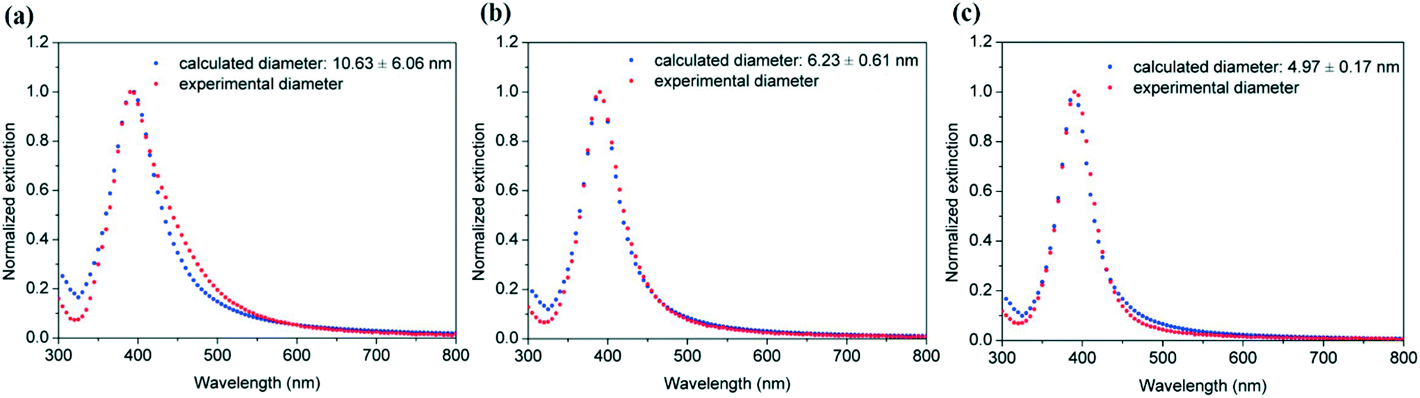
Fitting of these UV-vis spectra using the Mie model allows the estimation of the average particle sizes and distributions of 10.63 ± 6.06, 6.23 ± 0.61 and 4.97 ± 0.17 nm as the flow rate increases from 0.15, 0.5 and 0.7 mL min−1 respectively (Fig. 17). Decreasing the flow rate, considerably decreases the formation of transversal flows in helical reactors leading not only to considerably bigger particles but also to very high polydispersity.
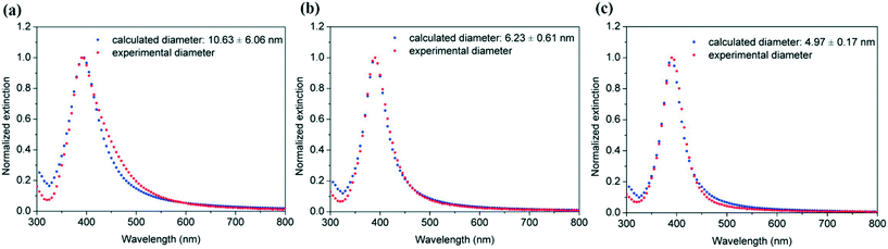 |
| | Fig. 17 Fitting of the experimental UV-vis spectra of silver nanoparticles synthesized in helical reactors with varying total flow rates of (a) 0.15 ml min−1, (b) 0.5 ml min−1 and (c) 0.7 ml min−1, a length of 130 cm, a helix diameter of 14 mm, and a helix diameter of 1/π mm with an AgNO3/NaBH4 molar ratio of 1:6 using the Mie model. | |
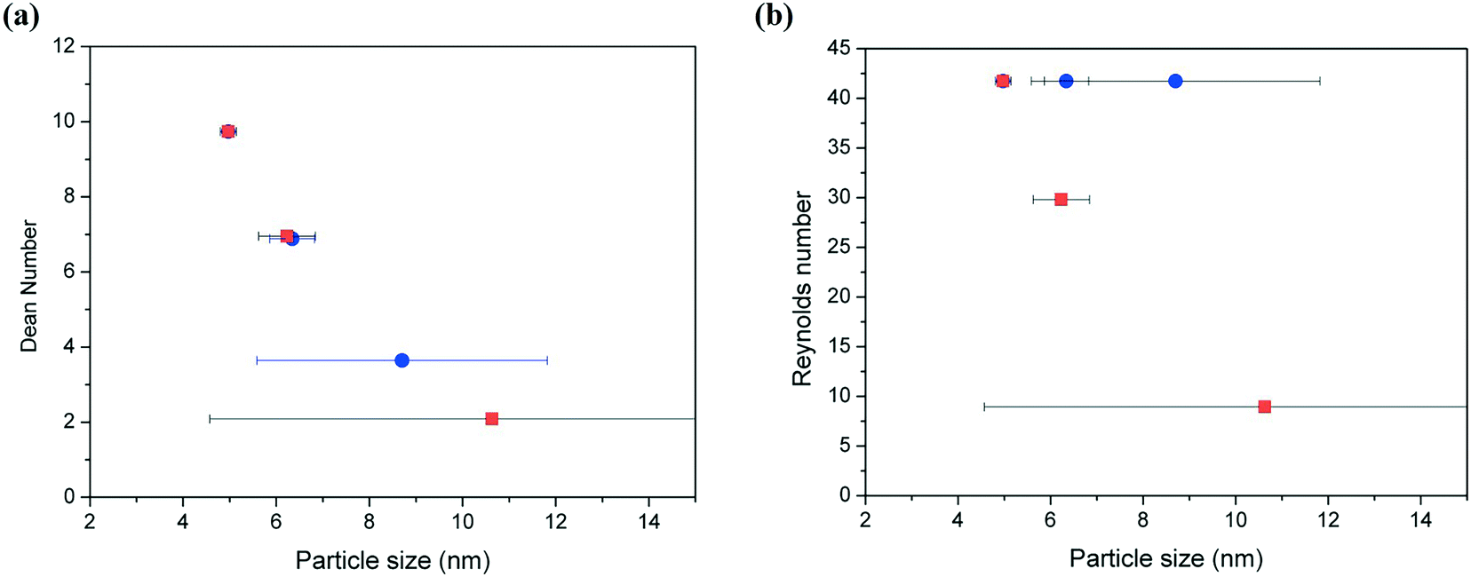
The degree of the secondary flow vortices in helical tubes is normally quantified by the dimensionless Dean number (eqn (1)), where both the curvature of the helical reactor (given by the helix diameter and the pitch distance) and the flow rate have an effect. Fig. 18a shows a clear relationship between the Dean number and average particle size and distribution of silver nanoparticles. As the Dean number increases, the particle size decreases and the size distribution becomes substantially narrower. The control of size distribution observed at high Dean numbers is due to the fast nucleation rate and homogeneous growth enabled by the good radial mixing promoted by the secondary flows. Contrary to this, at very low Dean number values (<5), no control of size is achieved with very broad size distribution observed due to the absence of capping ligands. The two sets of data shown in Fig. 18a represent variations of the Dean number by modifying the helix diameter of the reactors (●) and the total flow rate (■) while the rest of the parameters were kept constant. Thus, the relationships between Dean numbers and average particle size and distribution are valid independent of how such a Dean number value is achieved. Contrary to this, Fig. 18b shows the lack of relationship between the Reynolds number and the average particle size and distribution. In a similar way to that mentioned above, two sets of data are shown in the graph where silver nanoparticles are synthesized in helical reactors with similar Reynolds numbers but different curvature (data represented by ●) leading to very different average particle sizes and more importantly size distributions. This observation suggests that the particle size and particle size distribution is not only a function of Reynolds number. Furthermore, it is important to note here that very small values of Reynolds number will also lead to a very poor mixing at the T-mixer entrance of the reactor, promoting non-homogenous nucleation.
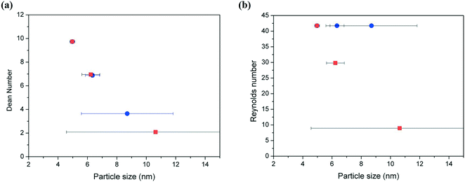 |
| | Fig. 18 Effect of (a) Dean number and (b) Reynolds number on the average particle size and polydispersity of silver nanoparticles synthesized in helical reactors. The data are obtained as a function of (●) helix diameter and (■) flow rate. | |
Conclusions
Narrow size distributions of silver nanoparticles synthesized in the absence of capping ligands can be achieved by promoting secondary flows in helical microreactors due to the promotion of fast nucleation and homogenous growth by radial mixing. Decreasing the helix diameter of the reactors leads to smaller particle sizes with considerably narrower size distributions. A similar effect is achieved by increasing the total flow rate, assuming that the Dean number is above ∼5; otherwise, even increasing the Reynolds number does not help narrow the particle size distribution. In addition, variation of the pitch distance of the helical reactor within the studied range herein does not seem to affect the particle size or its distribution as it does not affect the velocity profiles in the radial direction.
Acknowledgements
LTM would like to acknowledge the UK Engineering and Physical Science Research Council for her Fellowship award (grant number EP/L020432/2) and thanks Dr Ioannis Papakonstantinou for the useful discussions and help in the development of the Mie model.
References
- F. C. Walsh, D. V. Bavykin, L. Torrente-Murciano, A. A. Lapkin and B. A. Cressey, Trans. Inst. Met. Finish., 2006, 84, 293–299 CrossRef CAS.
- L. Torrente-Murciano, Q. He, G. J. Hutchings, C. J. Kiely and D. Chadwick, ChemCatChem, 2014, 6, 2531–2534 CrossRef CAS.
- L. Torrente-Murciano, T. Villager and D. Chadwick, ChemCatChem, 2015, 7, 925–927 CrossRef CAS.
- K. L. Kelly, E. Coronado, L. L. Zhao and G. C. Schatz, J. Phys. Chem. B, 2003, 107, 668–677 CrossRef CAS.
- F. E. Kruis, H. Fissan and A. Peled, J. Aerosol Sci., 1998, 29, 511–535 CrossRef CAS.
- A. H. Lu, E. L. Salabas and F. Schuth, Angew. Chem., Int. Ed., 2007, 46, 1222–1244 CrossRef CAS PubMed.
- C. Della Pina, E. Falletta, L. Prati and M. Rossi, Chem. Soc. Rev., 2008, 37, 2077–2095 RSC.
- L. Torrente-Murciano, A. A. Lapkin, D. V. Bavykin, F. C. Walsh and K. Wilson, J. Catal., 2007, 245, 272–278 CrossRef CAS.
- B. L. Cushing, V. L. Kolesnichenko and C. J. O'Connor, Chem. Rev., 2004, 104, 3893–3946 CrossRef CAS PubMed.
- Y. G. Sun and Y. N. Xia, Science, 2002, 298, 2176–2179 CrossRef CAS PubMed.
- S. H. Wu and D. H. Chen, J. Colloid Interface Sci., 2004, 273, 165–169 CrossRef CAS PubMed.
- T. S. Ahmadi, Z. L. Wang, T. C. Green, A. Henglein and M. A. ElSayed, Science, 1996, 272, 1924–1926 CrossRef CAS PubMed.
- S. Marre and K. F. Jensen, Chem. Soc. Rev., 2010, 39, 1183–1202 RSC.
- J. Wagner and J. M. Kohler, Nano Lett., 2005, 5, 685–691 CrossRef CAS PubMed.
- Z. L. Xue, A. D. Terepka and Y. Hong, Nano Lett., 2004, 4, 2227–2232 CrossRef.
- A. Knauer, A. Thete, S. Li, H. Romanus, A. Csaki, W. Fritzsche and J. M. Kohler, Chem. Eng. J., 2011, 166, 1164–1169 CrossRef CAS.
- V. S. Cabeza, S. Kuhn, A. A. Kulkarni and K. F. Jensen, Langmuir, 2012, 28, 7007–7013 CrossRef PubMed.
- S. A. Khan and S. Duraiswamy, Lab Chip, 2012, 12, 1807–1812 RSC.
- C. Y. Tai, Y. H. Wang, C. T. Tai and H. S. Liu, Ind. Eng. Chem. Res., 2009, 48, 10104–10109 CrossRef CAS.
- A. Jahn, J. E. Reiner, W. N. Vreeland, D. L. DeVoe, L. E. Locascio and M. Gaitan, J. Nanopart. Res., 2008, 10, 925–934 CrossRef CAS.
- S. I. Kawasaki, K. Sue, R. Ookawara, Y. Wakashima, A. Suzuki, Y. Hakuta and K. Arai, J. Supercrit. Fluids, 2010, 54, 96–102 CrossRef CAS.
- S. Gomez-de Pedro, M. Puyol and J. Alonso-Chamarro, Nanotechnology, 2010, 21, 415603 CrossRef CAS PubMed.
- P. Boldrin, A. K. Hebb, A. A. Chaudhry, L. Otley, B. Thiebaut, P. Bishop and J. A. Darr, Ind. Eng. Chem. Res., 2007, 46, 4830–4838 CrossRef CAS.
- K. P. Acharya, R. S. Khnayzer, T. O'Connor, G. Diederich, M. Kirsanova, A. Klinkova, D. Roth, E. Kinder, M. Imboden and M. Zamkov, Nano Lett., 2011, 11, 2919–2926 CrossRef CAS PubMed.
- K. A. Brown, M. B. Wilker, M. Boehm, G. Dukovic and P. W. King, J. Am. Chem. Soc., 2012, 134, 5627–5636 CrossRef CAS PubMed.
- N. Jain, A. Bhargava, M. Rathi, R. V. Dilip and J. Panwar, PLoS One, 2015, 10, e0134337 Search PubMed.
- J. A. Lopez-Sanchez, N. Dimitratos, C. Hammond, G. L. Brett, L. Kesavan, S. White, P. Miedziak, R. Tiruvalam, R. L. Jenkins, A. F. Carley, D. Knight, C. J. Kiely and G. J. Hutchings, Nat. Chem., 2011, 3, 551–556 CrossRef CAS PubMed.
- C. M. Chang, K. L. Orchard, B. C. M. Martindale and E. Reisner, J. Mater. Chem. A, 2016, 4, 2856–2862 CAS.
- T. Garcia, R. Murillo, S. Agouram, A. Dejoz, M. J. Lazaro, L. Torrente-Murciano and B. Solsona, Chem. Commun., 2012, 48, 5316–5318 RSC.
- A. K. Hill and L. Torrente-Murciano, Int. J. Hydrogen Energy, 2014, 39, 7646–7654 CrossRef CAS.
- S. Vashisth, V. Kumar and K. D. P. Nigam, Ind. Eng. Chem. Res., 2008, 47, 3291–3337 CrossRef CAS.
- W. R. Dean, Philos. Mag., 1927, 4, 208–223 CrossRef.
- B. Michen, C. Geers, D. Vanhecke, C. Endes, B. Rothen-Rutishauser, S. Balog and A. Petri-Fink, Sci. Rep., 2015, 5, 09793 CrossRef CAS PubMed.
- V. K. LaMer and R. H. Dinegar, J. Am. Chem. Soc., 1950, 72, 4847–4854 CrossRef CAS.
- J. Y. Shen, Z. Y. Li, Q. J. Yan and Y. Chen, J. Phys. Chem., 1993, 97, 8504–8511 CrossRef CAS.
- J. Polte, X. Tuaev, M. Wuithschick, A. Fischer, A. F. Thuenemann, K. Rademann, R. Kraehnert and F. Emmerling, ACS Nano, 2012, 6, 5791–5802 CrossRef CAS PubMed.
- M. Takesue, T. Tomura, M. Yamada, K. Hata, S. Kuwamoto and T. Yonezawa, J. Am. Chem. Soc., 2011, 133, 14164–14167 CrossRef CAS PubMed.
- R. Baber, L. Mazzei, N. T. K. Thanh and A. Gavriilidis, RSC Adv., 2015, 5, 95585–95591 RSC.
-
U. Kreibig and M. Vollmer, Optical Properties of Metal Clusters, 1995 Search PubMed.
- V. Amendola and M. Meneghetti, J. Phys. Chem. C, 2009, 113, 4277–4285 CAS.
-
G. A. Groβ and J. M. Koöhler, in Microfluidic Devices in Nanotechnology, John Wiley & Sons, Inc., 2010, DOI:10.1002/9780470622636.ch9, pp. 317–340.
- O. Levenspiel, B. W. Lai and C. Y. Chatlynne, Chem. Eng. Sci., 1970, 25, 1611–1613 CrossRef CAS.
- O. Levenspiel and J. C. R. Turner, Chem. Eng. Sci., 1970, 25, 1605–1609 CrossRef CAS.
- K. Yamamoto, T. Akita, H. Ikeuchi and Y. Kita, Fluid Dyn. Res., 1995, 16, 237–249 CrossRef.
|
| This journal is © The Royal Society of Chemistry 2017 |
Click here to see how this site uses Cookies. View our privacy policy here. 
 Open Access Article
 This Open Access Article is licensed under a
  *
*