 Open Access Article
Highly sensitive textile-based strain sensors using poly(3,4-ethylenedioxythiophene):polystyrene sulfonate/silver nanowire-coated nylon threads with poly-L-lysine surface modification
Jimi Eoma,
Jae-Sang Heob,
Minho Kimc,
Jun Ho Leeb,
Sung Kyu Park *b and
Yong-Hoon Kim
 *ac
*ac
aSKKU Advanced Institute of Nanotechnology (SAINT), Sungkyunkwan University, Suwon 16419, Korea. E-mail: yhkim76@skku.edu
bSchool of Electrical and Electronics Engineering, Chung-Ang University, Seoul 156-756, Korea. E-mail: skpark@cau.ac.kr
cSchool of Advanced Materials Science and Engineering, Sungkyunkwan University, Suwon 16419, Korea
First published on 20th November 2017
Abstract
Here, we demonstrate highly sensitive textile-based strain sensors using poly(3,4-ethylenedioxythiophene):polystyrene sulfonate (PEDOT:PSS)/silver nanowire (Ag NW)-coated nylon threads for electronic textile applications. For the coating of Ag NW and PEDOT:PSS layers, we employed a simple and cost-efficient ‘dip and dry’ method which facilitated conformal coating of Ag NWs and PEDOT:PSS on cylindrical-shaped nylon filaments. In this study, to improve the stability of the strain sensor, we employed poly-L-lysine (PLL) surface modification of nylon threads prior to the Ag NW coating process. By stability tests, it was found that the PLL surface modification significantly improved the operational stability of the strain sensor, attributed to the enhanced adhesion between Ag NWs and nylon thread. By mechanically sewing the PEDOT:PSS/Ag NW/nylon thread onto a fabric, a textile-based strain sensor was fabricated, exhibiting strain gauge factors of 1.69–3.31 (strain range of 5–20%) and stable operation up to ca. 1000 stretch–release cycles. Furthermore, as a possible extensive use of the PEDOT:PSS/Ag NW/nylon threads, a capacitive-type touch/pressure sensor was also demonstrated on a textile platform.
1. Introduction
Recently, electronic textiles have attracted considerable interest in the field of wearable electronics owing to their unique advantages such as draping properties, good flexibility, mechanical durability, and comfort.1–3 These advantages of electronic textiles have brought the development of various electronic devices made on textile platforms including sensors, displays, solar cells, energy generators and supercapacitors.4–10 Among the various types of textile-based electronic devices, strain and pressure sensors are of particular interest for their extensive uses in electronic textiles.11 For example, strain and pressure sensors can be embedded in clothing to monitor the tilt angles of a joint,12 observe muscle activity,13 or measure the pressure applied to the human body.14In order to realize textile-based strain and pressure sensors, a strain or pressure sensing component must be embedded in the textile. Although the conventional rigid metallic films or conducting elastomers could be used as a sensing component, conductive thread-type sensing elements are more preferable for electronic textiles since they are light-weight, fully flexible, and possess physical properties similar to those of common fabrics. Previously, Park et al. reported graphene strain sensors based on stretchable yarns for human motion monitoring.15 The strain sensor exhibited stretchability up to ∼150% and a gauge factor (G) of 1.4 within 150% of strain.15 Cheng et al. also demonstrated fiber strain sensors using reduced graphene oxide-coated polyester fibers winded on a polyurethane fiber.16 The strain sensor was capable of detecting multiple deformation and exhibited gauge factors of 10 within 1% of strain, and 3.7 within 50% of strain.16 In addition, various types of textile-based sensors were demonstrated using conductive sensing components such as poly(styrene-block-butadiene styrene)-coated fibres where conductive silver nanoparticles are synthesized on the surface of the fibre,17 carbon nanotube (CNT)-based conducting fibres,18 and poly(3,4-ethylenedioxythiophene):poly(styrene sulfonate) (PEDOT:PSS)-coated conducting fibres.19 Along with these sensing components, conductive threads comprising mechanically flexible silver nanowires (Ag NWs) or their composites can be also promising candidates owing to their great flexibility, stretchability, low electrical resistance, and low temperature processability (<120 °C).20–22 In fact, using the Ag NWs as a sensing component, highly sensitive strain sensors on two-dimensional structures have been demonstrated utilizing the percolation network structure of Ag NWs.23–25
Here, we demonstrate highly sensitive textile-based strain sensors using PEDOT:PSS/Ag NW-coated nylon threads as a strain sensing component for electronic textile applications. By using a simple and cost-efficient ‘dip and dry’ method, the conducting layers of Ag NW and PEDOT:PSS were successfully coated on cylindrical-shaped nylon filaments at low-temperatures. In addition, to improve the stability of the strain sensor, we employed poly-L-lysine (PLL) surface modification prior to the Ag NW coating process which significantly enhanced the adhesion of Ag NWs on nylon threads. Using the PEDOT:PSS/Ag NW/nylon threads, a textile-based strain sensor was fabricated exhibiting strain gauge-factors of 1.69–3.31 in a strain range of 5–20%. Also, the strain sensor was stably operated up to 1000 stretch–release cycles. Furthermore, as a possible extensive use of the PEDOT:PSS/Ag NW/nylon threads, a capacitive-type touch/pressure sensor was demonstrated which successfully identified the touching and pressing actions.
2. Experimental
Materials preparation
As a thread material, commercially available multifilament nylon thread was used. For the PLL surface modification of nylon threads, an aqueous PLL solution (0.1 w/vol% in H2O) was used without any modification (purchased from Sigma-Aldrich). For the Ag NW coating, an Ag NW ink (0.3 wt%) diluted in isopropanol alcohol was used (purchased from Nanopyxis). In addition, for the PEDOT:PSS coating, a pH-neutral PEDOT:PSS solution was first prepared (purchased from Ditto technology), and 10 wt% of glycerol was added to the PEDOT:PSS solution and thoroughly stirred to obtain a glycerol-doped PEDOT:PSS solution. The glycerol doping was carried out to enhance the electrical conductivity and the water stability of PEDOT:PSS layers.26–28PLL surface modification and PEDOT:PSS/Ag NW coating on nylon threads
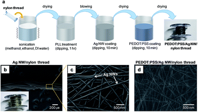
To fabricate a PEDOT:PSS/Ag NW-coated nylon thread, the multifilament nylon thread was first cleaned by sonication in methanol, ethanol, and de-ionized (DI) water for 10 min each and dried in a convection oven at 70 °C for 3 h (Fig. 1a). Afterward, PLL surface modification was carried out by immersing the nylon thread in an aqueous PLL solution for 1 h. Then, the PLL-modified nylon thread was dipped in an Ag NW ink for 10 min and dried at 70 °C for 30 min in a convection oven. The Ag NW coating and drying processes were repeated three times to obtain sufficient electrical conductivity. Next, the PEDOT:PSS coating process was carried out by immersing the Ag NW-coated nylon thread in a glycerol-doped PEDOT:PSS solution for 10 min and drying at 70 °C for 1 h. Finally, the PEDOT:PSS/Ag NW/nylon thread was dried at 120 °C for 30 min.Fabrication and characterization of textile-based strain and touch/pressure sensors
Textile-based strain sensors were fabricated by using PEDOT:PSS/Ag NW/nylon threads with PLL surface modification. For the fabrication of a strain sensor, the PEDOT:PSS/Ag NW/nylon thread was mechanically sewn onto a fabric using an automatic sewing machine (Brother, Innovis 55p). In the sewing process, an electrically insulating nylon thread was used as an interlocking thread to firmly interlock the PEDOT:PSS/Ag NW/nylon thread on the fabric and maintain the patterns. As sensor patterns, we employed a linear-type pattern which exhibits higher strain sensitivity and gauge factor compared to a zigzag-type pattern.4 For the analysis of sensing characteristics, the resistance variation of a strain sensor was analyzed in a strain range of 0–20% by using a source measure unit (Keithley, 2400). Here, the maximum strain value was set at 20% due to the limited stretchability of the PEDOT:PSS/Ag NW/nylon thread (∼25%). In addition, for the fabrication of capacitive-type touch/pressure sensors, two PEDOT:PSS/Ag NW/nylon threads were first sewn onto two separate fabrics. Afterward, with the two PEDOT:PSS/Ag NW/nylon threads facing each other, a double-sided adhesive (ca. 70 μm thick) was placed in between the fabrics and a pressure was applied to attached the two fabrics. The double-sided adhesive has the role of attaching the two fabrics together and also as a dielectric layer in a capacitor.The microstructures of nylon threads were investigated by using a field-emission scanning electron microscope (FESEM) (JEOL, JSM-7600F). The chemical structures of the Ag NW/nylon and Ag NW/PLL/nylon threads were analyzed using Fourier transform infrared spectroscopy (FT-IR) (ThermoFisher, Nicolet iS5), and the capacitance variation of touch/pressure sensors was analyzed by using a precision LCR meter (Agilent, 4284A), respectively.
3. Result and discussions
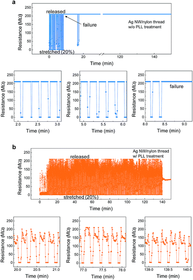
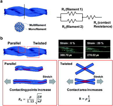
For the fabrication of PEDOT:PSS/Ag NW/nylon thread, Ag NWs were first coated on the nylon thread by ‘dip and dry’ method as shown in Fig. 1a. Fig. 1b and c show the SEM images of Ag NW-coated nylon thread with PLL surface modification. As shown here, Ag NWs with random orientation were uniformly coated on nylon thread successfully forming a percolation structure. As a result, the Ag NW/nylon thread showed relatively low resistance of ca. 509 Ω (measured with two probes displaced by ca. 1 cm on the thread). Here, prior to the Ag NW coating process, we applied PLL surface modification to nylon threads in order to improve the stability of the strain sensor. In fact, without the PLL surface modification, the strain sensors using Ag NW/nylon thread showed poor operational stability (Fig. 2a). To clearly determine the influence of PLL surface modification on the stability of the sensor, textile strain sensors using Ag NW/nylon threads with and without PLL surface modification were separately prepared and their operational stabilities were investigated. In the case of a strain sensor fabricated using an Ag NW/nylon thread without PLL modification, the sensor showed good responses to the applied strain up to ∼8.5 min of operation as shown in Fig. 2a. In this period, the resistance of the sensor decreased from ca. 200 MΩ to 0.1–1 MΩ when it was stretched with a strain of 20% (corresponds to a stress value of ∼0.6 GPa).29,30 However, after ∼8.5 min of operation (∼40 stretch–release cycles), the sensor was instantaneously failed and showed no response to the applied strain. We supposed that without the PLL surface modification, the Ag NWs are rather loosely adhere to the nylon surface, and likely to detach from the surface upon repeated stretch–release cycles. On the other hand, with the PLL surface modification applied prior to the Ag NW coating process, the stability of the sensor was significantly improved as shown in Fig. 2b. As displayed, the sensor was stable up to ∼600 stretch–release cycles without any noticeable failure. This significant improvement in stability can be attributed to the enhanced adhesion between Ag NWs and the nylon thread which led to a suppression of physical detachment of Ag NWs during the repeated stretch–release cycles.As shown in Fig. 2, the resistance of strain sensor decreased upon mechanical stretching. Such decrease of resistance at a stretched state can be explained by the enhanced percolation between the conductive nylon monofilaments,31,32 by which the conducting paths through the nylon threads were increased. In order to understand the mechanism more clearly, we adopted a resistance model (Fig. 3a), similar to those developed for describing the resistance variation in a carbon nanofiber yarn31 and a graphene-based fiber.16 Here, R1, R2 and Rc represent the filament-1 resistance, filament-2 resistance and contact resistance, respectively. As illustrated, the contact resistance plays an important role in determining the total resistance of the thread. As shown in Fig. 3b, the PEDOT:PSS/Ag NW/PLL/nylon thread consists of multiples of monofilaments which are aligned in parallel and twisted. Therefore, when the thread is stretched in a lateral direction, the contacting points between the monofilaments are likely to increase, which results in a decrease of resistance. Such an increase of contacting points can be partially supported by a decrease of thread diameter from 300.7 μm to 278.0 μm upon 20% of strain (Fig. 2b). In fact, the percolation behavior of the multifilament conducting thread can be explained by the Holm theory32 as shown below,
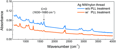
As shown in the stability tests, the PLL surface modification of nylon thread allowed enhanced stability of the Ag NW/nylon-based strain sensors. It is considered that the enhanced stability is attributed to the good adhesion of Ag NWs on nylon surface. Such improved adhesion by the PLL surface modification can be explained by the interactions occurring between nylon thread, PLL interlayer, and poly(vinyl pyrrolidone) (PVP) molecules which wrap around the Ag NWs.33,34 During the PLL surface modification, it is likely that nucleophilic addition reactions between amino groups (–NH2) in PLL molecule and carbonyl groups (C![[double bond, length as m-dash]](https://www.rsc.org/images/entities/char_e001.gif) O) in nylon thread occur,33 leading to a conformal coating of PLL on nylon thread surface. Afterward, during the Ag NW coating process, similar nucleophilic addition reaction33 and/or ring opening34 reaction could take place between the amino groups in PLL molecule and the carbonyl groups (C
O) in nylon thread occur,33 leading to a conformal coating of PLL on nylon thread surface. Afterward, during the Ag NW coating process, similar nucleophilic addition reaction33 and/or ring opening34 reaction could take place between the amino groups in PLL molecule and the carbonyl groups (C![[double bond, length as m-dash]](https://www.rsc.org/images/entities/char_e001.gif) O) in PVP molecule. These reactions then result in a tight binding between the nylon thread and Ag NWs, enhancing the adhesion strength. A possible evidence of nucleophilic addition reactions or ring opening induced by the PLL surface modification can be speculated by the FT-IR data. As shown in Fig. 4, with the PLL surface modification, the peak corresponding to amide C
O) in PVP molecule. These reactions then result in a tight binding between the nylon thread and Ag NWs, enhancing the adhesion strength. A possible evidence of nucleophilic addition reactions or ring opening induced by the PLL surface modification can be speculated by the FT-IR data. As shown in Fig. 4, with the PLL surface modification, the peak corresponding to amide C![[double bond, length as m-dash]](https://www.rsc.org/images/entities/char_e001.gif) O stretch (wavenumber of 1630–1680 cm−1)35 was reduced, which can be attributed to the nucleophilic addition and/or ring opening reactions at the nylon/PLL and PVP/PLL interfaces.
O stretch (wavenumber of 1630–1680 cm−1)35 was reduced, which can be attributed to the nucleophilic addition and/or ring opening reactions at the nylon/PLL and PVP/PLL interfaces.
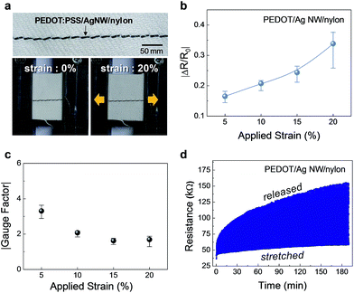
As described, with the PLL surface modification, the operational stability of Ag NW/nylon-based strain sensor was significantly improved. However, despite its decent stability, the Ag NW/nylon strain sensor showed a relatively high initial resistance (R0) of 100–200 MΩ, possibly due to the physical detachment or damages of Ag NWs during the mechanical sewing process. Therefore, to prevent the physical detachment and any damage of Ag NWs during the sewing process, a conducting passivation layer covering the Ag NWs was employed. Here, we use a conducting polymer PEDOT:PSS as a passivation layer. As shown in Fig. 1d, the PEDOT:PSS passivation layer completely covered the Ag NWs, and in addition, the voids between the Ag NWs were filled by the PEDOT:PSS. Due to the complete covering of Ag NWs by a conducting PEDOT:PSS layer, the physical detachment of Ag NWs during the sewing process can be effectively suppressed. Indeed, by using the PEDOT:PSS/Ag NW/nylon thread, a strain sensor having an initial resistance of 50–150 kΩ could be fabricated as shown in Fig. 5a and d. Fig. 5b shows the strain-dependent resistance change (ΔR/R0) of a PEDOT:PSS/Ag NW/nylon thread-based strain sensor as a function of applied strain. At 5% of strain, the ΔR/R0 value was −0.165 ± 0.011, and at 20% of strain, the ΔR/R0 was −0.338 ± 0.037, showing a reasonable linear relationship between resistance change and applied strain. In Fig. 5c, the corresponding gauge factor is shown as a function of applied strain. Here, the gauge factor of the sensor was calculated by the following equation, G = (|ΔR|/R0)/(ΔL/L0), where ΔL is the change in length and L0 is the initial length. In a strain range of 5–20%, the gauge factor of the sensor was 1.69–3.31 (Fig. 5b), which is comparably higher than that of PEDOT/polyester-based textile strain sensors.4
In Fig. 5d, the resistance variation of a PEDOT:PSS/Ag NW/nylon strain sensor during 1000 stretch–release cycles is displayed, where the strain value was set at 20% in stretched states. The results show that the PEDOT:PSS/Ag NW/nylon strain sensor was operable up to 1000 cycles without any critical failure, suggesting that the coated Ag NW and PEDOT:PSS layers were well adhered to the nylon thread during the repeated cycles. Despite its good stability, it should be noted that the resistance in released states was gradually increased with increasing cycles, while the resistance in stretched states were relatively unchanged. The gradual increase of resistance can be attributed to the partial cracking of PEDOT:PSS layer during the repeated stretch–release cycles,4 deteriorating the overall conductivity of the fibre. Therefore, in order to further enhance the stability of the sensor, the utilization of high elasticity conducting polymers, carbon-based materials or organic/inorganic hybrid materials needs to be considered as a passivation layer.
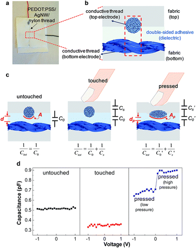
For further demonstration of textile-based electronics using PEDOT:PSS/Ag NW/nylon threads as a sensing component, a capacitive-type touch sensor was fabricated. Fig. 6a and b show an optical image and a schematic structure of the textile touch sensor, respectively. In the capacitive-type touch sensor, the two PEDOT:PSS/Ag NW/nylon threads work as the counter electrodes, while the double-sided adhesive film placed between the threads works as a dielectric layer, forming a capacitor structure. As shown in Fig. 6c, in an untouched state, the total capacitance of the cell (Ct) is given by the equation, Ct = C0 = ε × εr × A/d, where C0 is the capacitance of a capacitor formed by the top and bottom threads, ε the vacuum permittivity, εr the dielectric constant, A the effective capacitor area, and d the average distance between the two threads. In this untouched state, the total capacitance (Ct = C0) was measured as ∼0.5 pF as shown in Fig. 6d. In a touch state (touching the sensor with a finger without any pressure applied), an additional capacitor is formed by the finger and the top conducting thread, and, as a result, the total capacitance is changed to 1/Ct = 1/C0 + 1/Cs, where Cs is the capacitance of a capacitor formed by the finger and the top conducting thread. Because of the serially connected capacitor structure, the total capacitance of the cell was lowered to ∼0.35 pF, which gives a corresponding Cs value of ca. 1.17 pF.
Furthermore, the fabricated textile touch sensor could also distinguish the pressure applied to the sensor. As shown in Fig. 6d, by pressing the sensor with a finger at different pressures, the total capacitance of the sensor varied according to the magnitude of pressure. With a relatively low-pressure applied to the sensor, the total capacitance was increased to ∼0.7 pF, while, with a higher pressure applied, the capacitance was further increased to ∼0.9 pF. As a possible explanation of the capacitance increase with the pressure, a schematic illustration is given in Fig. 6c. Here, as illustrated, when touching the sensor with a pressure, the thickness of the adhesive film which is placed between the threads tends to decrease, and at the same time, because of the applied pressure, the effective capacitor area can be increased. Therefore, in the equation C = ε × εr × A/d, both the C0 and Cs are increased, which give a rise to the total capacitance (1/Ct = 1/C′0 + 1/C′s) of the sensor. According to these physical variations of active capacitance area and the dielectric thickness, the total capacitance is changed depending on the applied pressure, which enables the identification of applied pressure given to the capacitive-type textile sensors. Furthermore, the capacitive-type touch sensor was also capable of detecting the strain applied to the sensor. Particularly, the capacitance of the sensor was increased to ∼0.57 pF when a strain of 10% was applied to the sensor. The increase of capacitance value can be attributed to the reduction of the thickness of the dual-sided adhesive film upon a lateral stretching.
4. Conclusions
In this paper, we demonstrated highly sensitive and stable textile-based strain sensors using PEDOT:PSS/Ag NW/nylon threads. By using a simple and cost-efficient ‘dip and dry’ method, the conducting layers of Ag NW and PEDOT:PSS were successfully coated on the multifilament-type nylon threads. For the enhancement of the adhesion between Ag NWs and nylon threads, we employed PLL surface modification prior to the Ag NW coating process, which in turn, significantly enhanced the stability of the strain sensor. As a result, using the PEDOT:PSS/Ag NW/nylon threads, a textile strain sensor having high gauge factor and good operational stability could be fabricated. In addition, a capacitive-type touch/pressure sensor was also demonstrated using the PEDOT:PSS/Ag NW/nylon threads on textile platform which is capable of identifying the touch action and a pressure applied to the sensor.Conflicts of interest
There are no conflicts to declare.Acknowledgements
This research was supported by the project funded by Ministry of Trade, Industry & Energy, Republic of Korea (10048884), and was partially supported by the Chung-Ang University Graduate Research Scholarship in 2016.References
- W. Zeng, L. Shu, Q. Li, S. Chen, F. Wang and X. M. Tao, Adv. Mater., 2014, 26, 5310–5336 CrossRef CAS PubMed.
- Y. J. Yun, W. G. Hong, W. J. Kim, Y. Jun and B. H. Kim, Adv. Mater., 2013, 25, 5701–5705 CrossRef CAS PubMed.
- J. Yoon, Y. Jeong, H. Kim, S. Yoo, H. S. Jung, Y. Kim, Y. Hwang, Y. Hyun, W.-K. Hong, B. H. Lee, S.-H. Choa and H. C. Ko, Nat. Commun., 2016, 7, 11477 CrossRef CAS PubMed.
- J. Eom, R. Jaisutti, H. Lee, W. Lee, J. S. Heo, J. Y. Lee, S. K. Park and Y. H. Kim, ACS Appl. Mater. Interfaces, 2017, 9, 10190–10197 CAS.
- J. Lee, H. Kwon, J. Seo, S. Shin, J. H. Koo, C. Pang, S. Son, J. H. Kim, Y. H. Jang, D. E. Kim and T. Lee, Adv. Mater., 2015, 27, 2433–2439 CrossRef CAS PubMed.
- W. Kim, S. Kwon, Y. C. Han, E. Kim, K. C. Choi, S.-H. Kang and B.-C. Park, Adv. Electron. Mater., 2016, 2, 1600220 CrossRef.
- Z. Yang, J. Deng, X. Sun, H. Li and H. Peng, Adv. Mater., 2014, 26, 2643–2647 CrossRef CAS PubMed.
- W. Seung, M. K. Gupta, K. Y. Lee, K.-S. Shin, J.-H. Lee, T. Y. Kim, S. Kim, J. Lin, J. H. Kim and S.-W. Kim, ACS Nano, 2015, 9, 3501–3509 CrossRef CAS PubMed.
- Y. Meng, Y. Zhao, C. Hu, H. Cheng, Y. Hu, Z. Zhang, G. Shi and L. Qu, Adv. Mater., 2013, 25, 2326–2331 CrossRef CAS PubMed.
- L. Liu, Y. Yu, C. Yan, K. Li and Z. Zheng, Nat. Commun., 2015, 6, 7260 CrossRef CAS PubMed.
- Y. C. Lai, B. W. Ye, C. F. Lu, C. T. Chen, M. H. Jao, W. F. Su, W. Y. Hung, T. Y. Lin and Y. F. Chen, Adv. Funct. Mater., 2016, 26, 1286–1295 CrossRef CAS.
- H. S. Lee, H. C. Shin, T. E. Starner, S. M. Gilliland and C. Zeagler, US Pat., 9,316,481, 2016, Apr. 19.
- B. Zhou, M. Sundholm, J. Cheng, H. Cruz and P. Lukowicz, Pervasive Mob. Comput., 2017, 38, 331–345 CrossRef.
- S. Wang, S. Xuan, M. Liu, L. Bai, S. Zhang, M. Sang, W. Jiang and X. Gong, Soft Matter, 2017, 13, 2483–2491 RSC.
- J. J. Park, W. J. Hyun, S. C. Mun, Y. T. Park and O. O. Park, ACS Appl. Mater. Interfaces, 2015, 7, 6317–6324 CAS.
- Y. Cheng, R. Wang, J. Sun and L. Gao, Adv. Mater., 2015, 27, 7365–7371 CrossRef CAS PubMed.
- J. Lee, H. Kwon, J. Seo, S. Shin, J. H. Koo, C. Pang, S. Son, J. H. Kim, Y. H. Jang, D. E. Kim and T. Lee, Adv. Mater., 2015, 27, 2433–2439 CrossRef CAS PubMed.
- J. R. Bautista-Quijano, P. Pötschke, H. Brünig and G. Heinrich, Polymer, 2016, 82, 181–189 CrossRef CAS.
- J. Zhou, E. Q. Li, R. Li, X. Xu, I. A. Ventura, A. Moussawi, D. H. Anjum, M. N. Hedhili, D.-M. Smilgies and G. Lubineau, J. Mater. Chem. C, 2015, 3, 2528–2538 RSC.
- J. H. Yim, S. Joe, C. Pang, K. M. Lee, H. Jeong, J.-Y. Park, Y. H. Ahn, J. C. de Mello and S. Lee, ACS Nano, 2014, 8, 2857–2863 CrossRef CAS PubMed.
- T.-B. Song, Y. Chen, C.-H. Chung, Y. Yang, B. Bob, H.-S. Duan, G. Li, K.-N. Tu, Y. Huang and Y. Yang, ACS Nano, 2014, 8, 2804–2811 CrossRef CAS PubMed.
- T. Akter and W. S. Kim, ACS Appl. Mater. Interfaces, 2012, 4, 1855–1859 CAS.
- J. Wang, C. Yan, W. Kang and P. S. Lee, Nanoscale, 2014, 6, 10734–10739 RSC.
- W. Xiong, H. Liu, Y. Chen, M. Zheng, Y. Zhao, X. Kong, Y. Wang, X. Zhang, X. Kong, P. Wang and L. Jiang, Adv. Mater., 2016, 28, 7167–7172 CrossRef CAS PubMed.
- M. Amjadi, A. Pichitpajongkit, S. Lee, S. Ryu and I. Park, ACS Nano, 2014, 8, 5154–5163 CrossRef CAS PubMed.
- D.-J. Yun, Y. J. Jeong, H. Ra, J.-M. Kim, T. K. An, M. Seol, J. Jang, C. E. Park, S.-W. Rhee and D. S. Chung, J. Mater. Chem. C, 2015, 3, 7325–7335 RSC.
- E. Lewis, B. Mantha and R. P. Barber, EPJ Photovoltaics, 2014, 5, 50402 CrossRef.
- M. S. Kim, S. K. Park, Y.-H. Kim, J. W. Kang and J.-I. Han, J. Electrochem. Soc., 2009, 156, H782–H785 CrossRef CAS.
- T. Kawaguchi, J. Appl. Polym. Sci., 1959, 2, 56–61 CrossRef CAS.
- L. Shen, I. Y. Phang, L. Chen, T. Liu and K. Zeng, Polymer, 2004, 45, 3341–3349 CrossRef CAS.
- S. Chawla, M. Naraghi and A. Davoudi, Nanotechnology, 2013, 24, 255708 CrossRef CAS PubMed.
- H. Zhang, Meas. Sci. Technol., 2015, 26, 105102 CrossRef.
- T. Majtan, G. Bukovska and J. Timko, Folia Microbiol., 2004, 49, 635 CrossRef CAS.
- F. M. A. AL-Salami, A. N. M. AL-Sharify and K. J. Kadem, Journal of College of Education, 2011, 531–543 Search PubMed.
- E.-Y. Choi, K. Kim, C.-K. Kim and E. Kang, Sci. Rep., 2016, 6, 37010 CrossRef PubMed.
| This journal is © The Royal Society of Chemistry 2017 |

