DOI:
10.1039/C7RA10697A
(Paper)
RSC Adv., 2017,
7, 54266-54276
Phosphomolybdic acid immobilized on ionic liquid-modified hexagonal boron nitride for oxidative desulfurization of fuel†
Received
27th September 2017
, Accepted 17th November 2017
First published on 27th November 2017
Abstract
Hexagonal boron nitride supported catalysts have been well-developed in catalytic desulfurization, but struggle from the drain of catalytically active sites. Herein, an ionic liquid functionalized BN is constructed for stabilization of catalytic sites (phosphomolybdic acid, HPMo). A stable and well-dispersed supported catalyst was successfully obtained, which was confirmed by a series of characterizations. Detailed oxidative desulfurization experiments showed that the IL-induced high dispersity of the HPMo indicated a promising catalytic performance; meanwhile, the IL-assisted stability dominated an enhanced recycling performance. Additionally, the satisfying catalyst exhibited an excellent catalytic activity to numerous sulfur compounds and a fine resistance to interferents. Moreover, the possible reaction process was studied by GC-MS.
1. Introduction
In recent years, fossil fuels have been widely used in various fields, and 80% of energy around the world originates from fossil fuels. However, the sulfur content has turned to be a barrier to the quality of crude oil.1,2 Owing to the increasingly serious environmental pollution, regulations have been proposed by many countries to limit the sulfur content in fuel oils to not exceeding 10 ppm.3–5 Hence, numerous efforts have been devoted to seeking a more efficient method for reducing the sulfur content in fuel oils. Traditionally, the hydrodesulfurization (HDS) method has been industrially employed but struggles from many disadvantages including6–8 harsh reaction conditions and poorer removal efficiencies of aromatic organic sulfides, such as dibenzothiophene (DBT), 4,6-dimethyldibenzothiophene (4,6-DMDBT), etc. More recently, a milder desulfurization process, oxidative desulfurization (ODS), which shows excellent performance in the oxidation of aromatic sulfur compounds, have been developed.6,9–13 The oxidative desulfurization process involves oxidation of sulfur compounds for an enhanced polarity and further adsorptive or extractive removal.14–16
In terms of the sulfur oxidation process, numerous reports have demonstrated that heteropoly acid (HPA) and its derivatives are a branch of high-efficiency catalysts.17–19 Although some advantages of HPAs, including strong Brönsted acid, oxidation-reduction, and structural selectivity properties, can be expected, numerous shortages are still inevitable. For example, low specific surface areas, poor stability, and dissolution property.20,21 To avoid the disadvantages, loading HPAs onto a certain support has been proved to be an effective strategy for high catalytic activity and excellent stability.22–24
Among all current supports, hexagonal boron nitride (h-BN) is one of the most favorable ones because of the high specific surface areas, layered structure, excellent thermal stability and so on.25–33 However, all current reported h-BN supported catalysts were gained by impregnation process, leading to the poor dispersion and agglomeration during the catalytic performance, especially in liquid phase reactions such as oxidative desulfurization, leading to the poorer recycling performance. Some more advanced supporting methods are thusly called. In colloid chemistry, long organic chains are often employed as media to prevent the aggregation of active sites.34,35 Additionally, HPAs are proved can be uniformly dispersed in organic media, such as ionic liquids. Further inspired by the nature of h-BN, which holds numerous functional groups on its surface, which can be modified as functional sites for grafting ionic liquids, further disperse the HPAs uniformly.
In this work, the graphene-like h-BN was functionalized by ionic liquids (BN-IL) and further employed as a functional support for dispersion of phosphomolybdic acid (H3PMo12O40, HPMo) to obtain a highly-active catalyst (HPMo/BN-IL). Owing to the functionalized property of the BN-IL, both high dispersion and excellent stability of the supported HPMo can be expected. The as-prepared heterogeneous catalyst was further characterized detailedly. The obtained HPMo/BN-IL was further applied in oxidative desulfurization process, showing a promising performance in catalytic oxidation of dibenzothiophene (DBT), 4,6-dimethyldibenzothiophene (4,6-DMDBT) and 3-methylbenzothiophene (3-MBT). Because of the enhanced stability, a better recycling performance was acquired, compared with that without IL functionalization. The current work would provide a new strategy for preparation of h-BN supported catalysts.
2. Experimental section
2.1 Materials
N-Methylimidazole (C4H6N2, C.P. grade), anhydrous diethyl ether (C4H10O, A.R. grade), diboron trioxide (B2O3, A.R. grade), urea (CO(NH2)2, A.R. grade), toluene (C6H5CH3, A.R. grade), dichloromethane (CH2Cl2, A.R. grade), anhydrous ethanol (C2H5OH, A.R. grade), phosphomolybdic acid (H3PMo12O40, aliased as HPMo, A.R. grade), n-octane (C8H18, A.R. grade), tetradecane (n-C14H30, 99%), hydrogen peroxide (H2O2, 30 wt%), cyclohexene (C6H10, A.R. grade), paraxylene(C6H4(CH3)2, A.R. grade), acetone (CH3COCH3, A.R. grade), commercial bulk boron nitride (aliased as commercial-BN, 98%) were derived from Shanghai Sinopharm Chemical Reagent Co., Ltd. (3-Chloropropyl) trimethoxysilan (C6H15ClO3Si, 98%) was purchased from Aladdin Chemistry. 4,6-Dimethyldibenzothiophene (4,6-DMDBT, 97%), dibenzothiophene (DBT, 98%), benzothianaphthene (BT, 99%) and 3-methylbenzothiophene (3-MBT, 96%) were marketed by Sigma-Aldrich.
2.2 Preparation process of catalysts
2.2.1 Synthesis of ionic liquids (IL). 10.3160 g (0.1258 mol) of freshly distilled N-methylimidazole and 25 g (0.1258 mol) of (3-chloropropyl)trimethoxysilan were added into a round-bottom flask and refluxed at 95 °C for 24 h with continuous stirring. After being cooled to room temperature, the obtained viscous liquid is washed with anhydrous diethyl ether and then transferred to a vacuum oven at 40 °C for 12 h. The collected faint yellow viscous liquid is the prepared ionic liquids (IL).
2.2.2 Preparation of h-BN. 0.6962 g (0.01 mol) of B2O3 and 12.012 g (0.2 mol) of CO(NH2)2 are added to a beaker with 40 mL of ultrapure water. Then the beaker with mixture was transferred to an isothermally heated oil bath at 60 °C with continuous stirring to completely evaporate the solvent. Afterwards, the obtained white crystal was transferred into a tube furnace, and the calcining process was as follows: the crystal mixtures are thermally treated from room temperature to 550 °C with a heating ratio of 5 °C min−1 and then kept for 120 min; then the tube furnace was further treated from 550 °C to 1000 °C at 5 °C min−1 and kept for another 120 min. The tube furnace was protected by N2 atmosphere during calcining process. After cooling to room temperature, the white products are collected and denoted as h-BN
2.2.3 Preparation of BN-IL. 1.0 g of h-BN and 0.5 g of IL are added to a round-bottom flask and dispersed into 50 mL of toluene. Then the flask with mixtures was refluxed at 90 °C for 16 h with continuous stirring. After cooling to room temperature, the mixtures are filtrated and then washed by CH2Cl2 to remove the unreacted IL to get white products. Finally, the white products are put into a vacuum oven at 60 °C for 12 h. The obtained white powder is the ionic liquid-modified h-BN, which denoted as BN-IL.
2.2.4 Preparation of HPMo/BN-IL catalyst. 0.04 g of HPMo was dissolved in 20 mL of anhydrous ethanol with stirring for 30 min, then 0.16 g of BN-IL was also added and stirred for 8 h. Then the mixture was washed with anhydrous ethanol and dried by a dryer at 100 °C for 12 h. The obtained faint yellow powder is the prepared HPMo/BN-IL catalyst with 20 wt% of loading amounts, which denoted as 20% HPMo/BN-IL. Other x% HPMo/BN-IL catalysts (x = 5, 10, 30) were prepared by the same process, just changed the amount of HPMo.The preparation process of HPMo/commercial-BN-IL is similar to that of HPMo/BN-IL catalyst, merely replacing the h-BN with commercial-BN.
2.2.5 Preparation of HPMo/BN catalyst. 0.04 g of HPMo was dissolved in 20 mL of anhydrous ethanol with stirring for 30 min, then 0.16 g of h-BN was also added and stirred for 8 h to fully disperse. Then the mixture was washed with anhydrous ethanol and dried at 100 °C for 12 h. The obtained white powder is the prepared HPMo/BN catalyst with 20% (wt%) of loading amounts for HPMo, which denoted as 20% HPMo/BN.
2.3 Characterization
X-ray diffraction (XRD) micrographs of all samples were analyzed by a D8 Advanced X-ray diffraction to detect crystal structures of samples, which was operated with Cu Kα radiation. Using a Hitachi H-700 transmission electron microscope to record transmission electron microscopy (TEM) images to examine structures and morphologies of various samples. All samples were conducted by a Nicolet Nexus 470 Fourier transform infrared spectrometer, which is equipped with a KBr pellets at room temperature, to receive the Fourier transform infrared spectroscopy (FT-IR) spectra. An ESCALAB250 (Thermo VG, UK) system with 1486.6 eV of standard monochromatic Al Kα excitation was used to analyze X-ray photoelectron spectroscopy (XPS) spectra. Structural information of samples was exhibited in Raman spectra, which was acquired from a Thermo Scientific DXR Smart Raman spectrometer with a 532 nm excitation. A Shimadzu UV-2450 spectrophotometer was operated to measure ultraviolet-visible diffuse reflectance spectroscopies (UV-vis DRS) of samples, which was run with a spherical diffuse reflectance accessory. A TriStar II 3020 surface-area and porosity analyzer were implemented to test nitrogen adsorption–desorption isotherms and pore-size distribution curves of various samples. Gas chromatography-mass spectrometry (GC-MS) was performed to observe products and mechanism of the catalytic system.
2.4 Oxidative desulfurization process
2.4.1 Preparation of model oil. The preparation process of 4,6-DMDBT, DBT, 3-MBT and BT model oil: a certain amount of 4,6-DMDBT, DBT, 3-MBT, and BT were respectively dissolved in n-octane with sulfur contents of 500 ppm, which metered volume by tetradecane. And the corresponding concentrations of internal standard were 1000 ppm, 4000 ppm, 1000 ppm and 500 ppm, respectively.The preparation process of interferential model oil for 4,6-DMDBT: a certain amount of cyclohexene, methylbenzene, and paraxylene were respectively dissolved in 4,6-DMDBT model oil to obtain cyclohexene interference oil, methylbenzene interference oil and paraxylene interference oil. And the corresponding sulfur content and internal standard concentrations are 500 ppm and 1000 ppm, respectively.
The preparation process of mixed interferential model oil for 4,6-DMDBT: a certain amount of cyclohexene, methylbenzene, and paraxylene are simultaneously dissolved in 4,6-DMDBT model oil to obtain mixed interferential model oil. And the corresponding sulfur content and internal standard concentration are also 500 ppm and 1000 ppm, respectively.
2.4.2 Oxidative desulfurization. The reaction equipment of oxidation desulfurization for model oil was carried out in a home-made two-necked flask. In turn, 0.05 g of catalyst and 5 mL of model oil were added into a two-necked flask, and a certain amount of 30 wt% H2O2 was also added after stirring. The reaction was operated in a thermostatic water bath with constant stirring. During the process of reaction, the upper oil phase was periodically withdrawn, and 1 μL of oil phase was injected into a gas chromatography detector to detect the residual sulfur content. Other active experiments were operated by a similar process, only changing reaction factors. The residual sulfur content was used to calculate removal rate of sulfide, which represents the activity of the catalyst in ODS.Residual sulfur content is measured by a gas chromatography-flame ionization detector (GC-FID, Agilent 7890A, HP-5 column, 30 m long × 0.32 mm inner diameter (id) 0.25 μm film thickness), using tetradecane as an internal standard.
3. Results and discussion
3.1 X-ray diffraction analysis
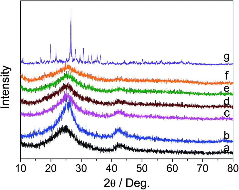
The X-ray diffraction (XRD) patterns of h-BN, BN-IL, HPMo and x% HPMo/BN-IL catalysts are displayed in Fig. 1. As seen from Fig. 1a, two obvious characteristic peaks for the hexagonal phase of BN at 2θ = 23.8° and 41.9° were clearly detected, respectively attributable to the (002) and (100) lattice planes (JCPDS Card no. 34-0421).36–38 The two peaks were also found in BN-IL (Fig. 1b), indicating the stability of h-BN during the IL grafting process. Also, the stability property also existed within the loading of HPMo onto BN-IL (Fig. 1c–f). No characteristic peaks for HPMo were detected in HPMo/BN-IL, which is assigned to the low loading amount and high dispersion of HPMo on BN-IL.
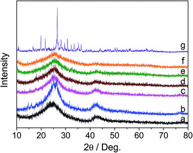 |
| | Fig. 1 XRD patterns of all samples. (a) h-BN; (b) BN-IL; (c) 5% HPMo/BN-IL; (d) 10% HPMo/BN-IL; (e) 20% HPMo/BN-IL; (f) 30% HPMo/BN-IL; (g) HPMo. | |
3.2 TEM and EDS-mapping analysis
In order to study morphology and structure information of HPMo on the carrier, the transmission electron morphologies (TEM) of h-BN and 20% HPMo/BN-IL catalyst were performed in Fig. 2. TEM images of h-BN in Fig. 2a and b show that h-BN was a layered structure with numerous pores. As can be seen from Fig. 2c and d, the lamellar structure and porous structure of h-BN were retained without damage in HPMo/BN-IL after immobilization, demonstrating the stability of h-BN in the preparation process. Notably, with the presence of HPMo, no clear section for HPMo was detected in the TEM image indicating the uniform dispersion of the HPMo with the grafting of ILs on BN. The similar conclusion can be also obtained from the (Energy Disperse Spectroscopy) EDS mapping characterization in Fig. S1,† that the Mo element is uniformly dispersed.
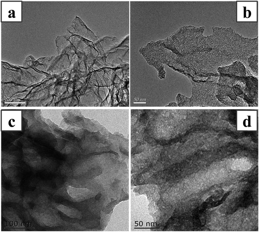 |
| | Fig. 2 TEM images of samples. (a, b): h-BN; (c, d): 20% HPMo/BN-IL. | |
3.3 FT-IR characterization
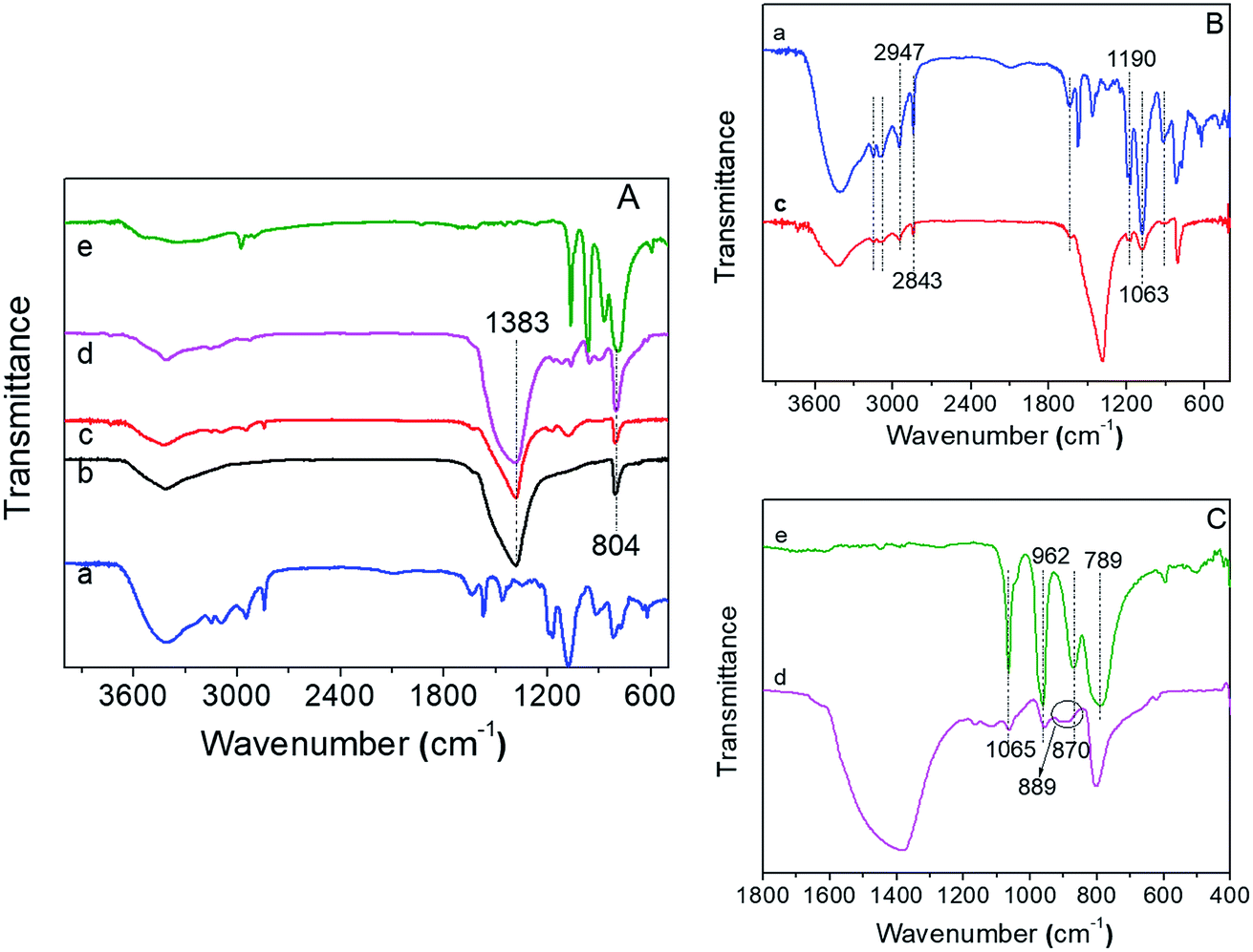
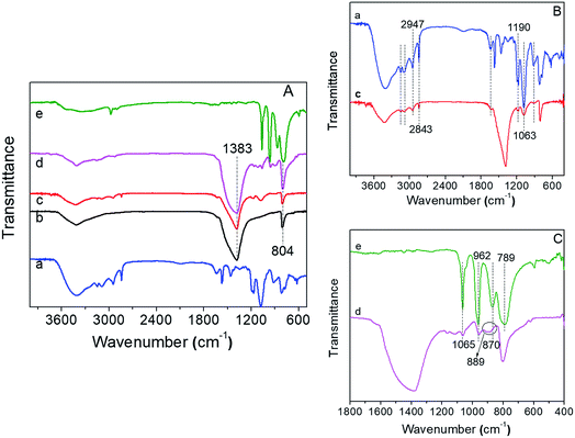
To further verify the immobilization process, the FT-IR spectra of all samples are shown in Fig. 3. Fig. 3a showed the FT-IR spectra of IL, h-BN, BN-IL, HPMo/BN-IL, and HPMo. As can be seen from Fig. 3a, the prepared h-BN exhibited two strong absorption peaks at 804 cm−1 and 1383 cm−1, which belong to the B–N–B stretching vibration mode and in-plane B–N transverse optional mode of h-BN,37,39 respectively. In the FT-IR spectrum of BN-IL sample, besides the absorption peaks of h-BN, some peaks of IL were also detected (Fig. 3b). The peaks around 1063 cm−1 and 1190 cm−1 are consistent with in-plane C–H absorption peaks of the benzene ring, and the 2843 cm−1 and 2947 cm−1 are assigned to C–H stretching absorption peaks,8,40 showing that the IL had been successfully immobilized onto h-BN. Moreover, the characteristic peaks for the Keggin structure of HPMo were detected at 789 cm−1 (Mo–Oc–Mo corner sharing), 870 cm−1 (Mo–Ob–Mo edge sharing), 962 cm−1 (P–O–P vibration mode) and 1065 cm−1 (Mo–Od vibration mode),41–43 respectively. Obviously, the main absorption peaks of h-BN and partial peaks of IL and HPMo were also observed on HPMo/BN-IL catalyst, indicating the successful immobilization of HPMo on BN-IL carrier. However, owing to the cover of 804 cm−1 peaks in h-BN, the 789 cm−1 peak of HPMo was not detected on HPMo/BN-IL. In addition, for HPMo/BN-IL, the 870 cm−1 peak of HPMo shifted to higher wavenumber (Fig. 3c), which is attributed to the interaction between HPMo and BN-IL.
 |
| | Fig. 3 FT-IR patterns of all samples. (a) IL; (b) h-BN; (c) BN-IL; (d) HPMo/BN-IL; (e) HPMo. | |
3.4 X-ray photoelectron spectroscopy
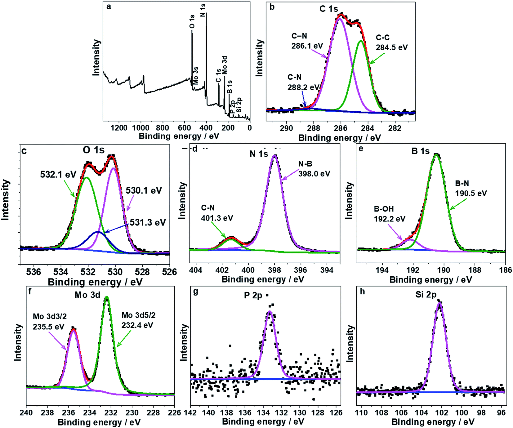
The chemical composition of catalysts was further analyzed by X-ray photoelectron spectroscopy (XPS) in Fig. 4. As seen from Fig. 4a, the HPMo/BN-IL was composed of O, C, N, B, Mo, P and Si elements, showing that the HPMo and IL were successfully introduced onto h-BN. Fig. 4b–e are the high-resolution spectra of C 1s, O 1s, N 1s and B 1s core level. The C 1s core level was divided into three peaks at 284.5 eV, 286.1 eV and 288.2 eV, corresponding to C–C, C![[double bond, length as m-dash]](https://www.rsc.org/images/entities/char_e001.gif) N and C–N state,44,45 respectively. The O 1s core level was separated into three peaks, locating at 530.1, 531.3, and 532.1 eV, respectively attribute to Mo–O, O2− for HPMo and –OH groups on the surface of h-BN.,46–48 respectively. The N 1s peak in Fig. 4d could be separated into N–B and C–N state, and the binding energies of them were 398.0 eV and 401.3 eV (ref. 37 and 44), respectively. Fig. 4e shows that the B 1s peak can be divided into B–N (190.5 eV) and B–OH (192.2 eV) state.37,49 Compared to the N 1s and B 1s core level of h-BN in reported literature, the current prepared BN is a hexagonal phase structure.44,50 Fig. 4f is the high-resolution spectra of Mo 3d core level. After a careful comparison with the previous report, the peaks for Mo 5d around 232.40 eV and 235.6 eV are respectively attributed to Mo 3d5/2 and Mo 3d3/2, and the valence state of Mo is a +6. The result shows that the HPMo is rather stable during the loading process.,51–54 respectively. Fig. 4g and h are the high-resolution spectra of P 2p and Si 2p core level, the binding energies of them were 133.3 eV and 102.2 eV, respectively. The analysis results of XPS spectra are consistent with the results in FT-IR spectra.
N and C–N state,44,45 respectively. The O 1s core level was separated into three peaks, locating at 530.1, 531.3, and 532.1 eV, respectively attribute to Mo–O, O2− for HPMo and –OH groups on the surface of h-BN.,46–48 respectively. The N 1s peak in Fig. 4d could be separated into N–B and C–N state, and the binding energies of them were 398.0 eV and 401.3 eV (ref. 37 and 44), respectively. Fig. 4e shows that the B 1s peak can be divided into B–N (190.5 eV) and B–OH (192.2 eV) state.37,49 Compared to the N 1s and B 1s core level of h-BN in reported literature, the current prepared BN is a hexagonal phase structure.44,50 Fig. 4f is the high-resolution spectra of Mo 3d core level. After a careful comparison with the previous report, the peaks for Mo 5d around 232.40 eV and 235.6 eV are respectively attributed to Mo 3d5/2 and Mo 3d3/2, and the valence state of Mo is a +6. The result shows that the HPMo is rather stable during the loading process.,51–54 respectively. Fig. 4g and h are the high-resolution spectra of P 2p and Si 2p core level, the binding energies of them were 133.3 eV and 102.2 eV, respectively. The analysis results of XPS spectra are consistent with the results in FT-IR spectra.
 |
| | Fig. 4 XPS spectra of (a) survey, (b) C 1s core level, (c) O 1s core level, (d) N 1s core level, (e) B 1s core level, (f) Mo 3d core level, (g) P 2p and (h) Si 2p core level in 20% HPMo/BN-IL catalyst. | |
3.5 Raman analysis
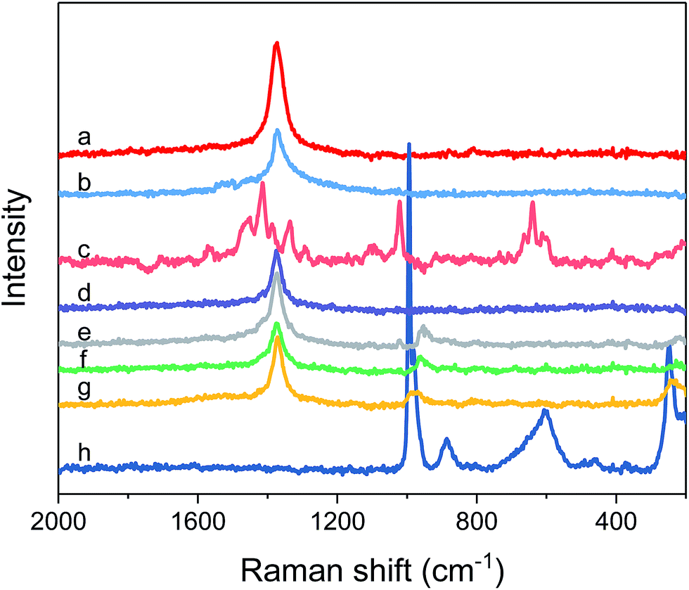
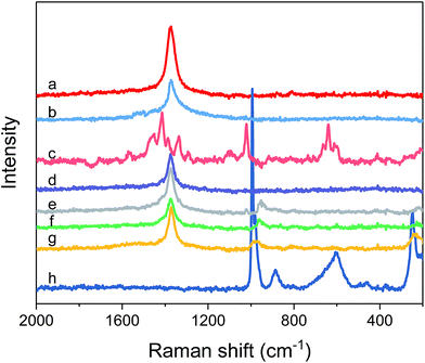
Other structural information of catalysts was further obtained from Raman spectra in Fig. 5. As seen from Fig. 5, an obvious peak for h-BN is detected around 1372.9 cm−1, which belongs to the B–N tangential vibration mode (E2g) of h-BN,55 showing the hexagonal phase structure. The E2g peak of h-BN was still observed on the BN-IL and x% HPMo/BN-IL catalysts, which illustrated that the structure of h-BN was not destroyed after the introduction of HPMo and IL. The peaks of IL at 2841.8 cm−1 and 2950.7 cm−1 were observed in the Raman image of BN-IL. The results state that the IL was successfully introduced onto the surface of h-BN. The x% HPMo/BN-IL catalysts also exhibited the characteristic peaks of IL, indicating the existence of IL on catalysts. Characteristic peaks of HPMo were detected around 994 cm−1, 886 cm−1 and 599 cm−1, which are assigned to the MoO symmetric stretch vibration, Mo–Oc–Mo symmetric bending of edge-shared bridge oxygen and O–P–O vibration,56,57 respectively. In addition, the 249 cm−1, 164 cm−1 and 107 cm−1 peaks were derived from the MoO3 group of HPMo.58,59 The 994 cm−1 and 249 cm−1 peaks of HPMo were also observed in 10%, 20%, and 30% HPMo/BN-IL catalysts, declaring the successful immobilization of HPMo on BN-IL carrier. However, the characteristic peaks of HPMo were not detected on 5% HPMo/BN-IL catalyst, owing to the lower loadings of HPMo on BN-IL.
 |
| | Fig. 5 Raman spectra of all catalysts. (a) h-BN; (b) BN-IL; (c) IL; (d) 5% HPMo/BN-IL; (e) 10% HPMo/BN-IL; (f) 20% HPMo/BN-IL; (g) 30% HPMo/BN-IL; (h) HPMo. | |
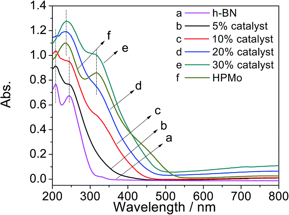
3.6 UV-vis DRS analysis
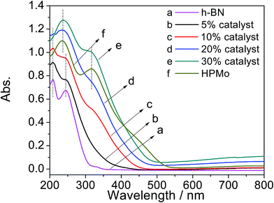
Fig. 6 presents the UV-vis DRS spectra of h-BN, x% HPMo/BN-IL catalysts and HPMo. As seen from Fig. 6a, two obvious signal peaks of h-BN were detected at 209 nm and 244 nm, and the two peaks also appeared in 5% and 10% HPMo/BN-IL catalysts, which suggested that the structure of h-BN was not changed after the introduction of HPMo. For HPMo in Fig. 6f, there were two signal peaks at 233 nm and 317 nm, attributing to the Keggin structure of heteropoly anion.41,60,61 Meanwhile, the two signal peaks were also clearly observed in 20% and 30% HPMo/BN-IL catalysts, hinting the successful introduction of HPMo into h-BN. However, because of the lower loadings of HPMo or the great dispersion of HPMo on BN-IL, the two peaks of HPMo could not be clearly detected in 5% and 10% HPMo/BN-IL catalysts. The results are consistent with that in Raman analysis.
 |
| | Fig. 6 UV-vis DRS patterns of all catalysts. (a) h-BN; (b) 5% HPMo/BN-IL; (c) 10% HPMo/BN-IL; (d) 20% HPMo/BN-IL; (e) 30% HPMo/BN-IL; (f) HPMo. | |
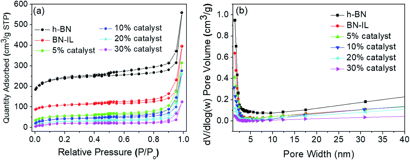
3.7 Nitrogen adsorption/desorption isotherms and pore size distribution curves
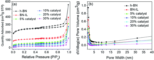
Fig. 7 exhibits the N2 adsorption/desorption isotherms and corresponding pore size distribution curves of h-BN, BN-IL, and x% HPMo/BN-IL catalysts. As can be seen from Fig. 7a, all samples showed the typical II isotherms with obvious H3 hysteresis loops, and the starting points of hysteresis loops were in the range of P/P0 = 0.45–0.55. The results suggested that the pore structures of h-BN, BN-IL, and x% HPMo/BN-IL catalysts were all mesoporous structure, which originated from slit-pore of layer material,37 and the mesoporous structures were not changed after heterogenization. Compared with h-BN, the adsorption capacities of hysteresis loops in BN-IL and x% HPMo/BN-IL reduce clearly. The results indicated that the IL and HPMo were successfully immobilized on h-BN, and the introduction of IL and HPMo led to the decrease of the specific surface area for h-BN. The decrease of specific surface areas (SSA) is mainly attributed to following reasons: even though the h-BN is an excellent material with a rather high SSA, the grafting of IL may cause the blocking of micropores, which is proved by the pore size distribution curves (Fig. 7b). Additionally, the agglomeration of h-BN is also inevitable because of the existence of long organic ligands on the surface. When HPMo was loaded onto the BN-IL, the SSA further decreased. The decrease of the SSAs mainly origins from the very low SSA of HPMo and the SSA is thusly decreases with the increase of HPMo loading amount.
 |
| | Fig. 7 Nitrogen adsorption–desorption isotherms (a) and pore size distribution curves (b) of h-BN, BN-IL and x% HPMo/BN-IL. | |
3.8 Influence of different catalysts on the removal of 4,6-DMDBT
Table 1 shows the effects of different catalysts on the removal of 4,6-DMDBT. When only with the HPMo as a catalyst, the catalytic activity for 4,6-DMDBT was very low to 8.6%; and even with the H2O2 as the oxidant, the removal of 4,6-DMDBT was only 14.7% (entry 1). However, when immobilizing HPMo onto h-BN (entry 2), the catalytic activity of HPMo/BN catalyst for 4,6-DMDBT reached up to 89.1%, implying the superiority of h-BN as a carrier and the promising activity of HPMo/BN heterogeneous catalyst. Noticeably, with ionic liquid-modified h-BN (BN-IL) as a carrier, the catalytic activity of HPMo/BN-IL catalyst (entry 3) improved to 94.3. It is because that the immobilization of IL on h-BN could improve the hydrophobicity of catalyst, leading to a better miscibility among catalyst, oxidant and model oil. As can be noticed in entry 4, when replacing h-BN with commercial-BN, the 4,6-DMDBT removal was only 21.4%. It can be attributed to the great specific surface area and mesoporous structure of h-BN, generating a better dispersion of HPMo on the carrier. Hence, the HPMo/BN-IL is a high-efficiency catalyst in ODS field. To verify the importance of high dispersion for HPMo and IL, a simple physical mixing of h-BN, IL and HPMo was applied in ODS system (entry 5). The experiment showed that the removal for 4,6-DMDBT was only 67.3%, further illustrating the importance of high dispersion. Obviously, the excellent activity of HPMo/BN-IL for 4,6-DMDBT could be attributed to two aspects: the enhanced hydrophobicity of catalyst induced better miscibility with model oil and the high specific surface area of h-BN. To exclude the possibility of catalytic activity of h-BN, we employed h-BN as a catalyst, the sulfur removal is only 32.50%, close to the adsorptive desulfurization performance of h-BN (entry 6), indicating that the h-BN can only show adsorption performance, which is in favor of the catalytic performance.
Table 1 Influence of different catalysts on 4,6-DMDBT
| Entry |
Catalytic systems |
Sulfur removal (%) |
| Catalyst |
Catalyst + H2O2 |
| This amount is equal with the loadings of HPMo in 20% HPMo/BN-IL catalyst. Reaction condition: T = 40 °C; n (O)/n (S) = 4; V (oil) = 5 mL; m (catalyst) = 0.05 g; t = 100 min. |
| 1a |
HPMo |
8.6 |
14.7 |
| 2 |
HPMo/BN |
31.5 |
89.1 |
| 3 |
HPMo/BN-IL |
38.6 |
94.3 |
| 4 |
HPMo/commercial-BN-IL |
3.1 |
21.4 |
| 5 |
BN + IL + HPMo |
23.4 |
67.3 |
| 6 |
h-BN |
32.0 |
32.5 |
3.9 Effect of loading amounts of HPMo on the removal of 4,6-DMDBT
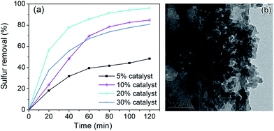
The x% HPMo/BN-IL catalysts were applied into ODS system to investigate the effect of HPMo loading amounts on catalytic activity, and the results are depicted in Fig. 8. As seen from Fig. 8a, when the loading amount of HPMo increased from 5% to 20%, the removal rates gradually decreased. However, when the HPMo loading further increased to 30%, the catalytic activity descended. To explain the phenomenon, the transmission electron microscope (TEM) image of 30% HPMo/BN-IL catalysts was recorded in Fig. 8b. In Fig. 8b, an extensive reunion phenomenon of HPMo was observed. It is precisely attributed to that the higher HPMo loading generates aggregation of HPMo on h-BN, which leads to the decrease of specific surface area and the blocking of pore structures, and further hinder the exposure of active sites. The above results are consistent with the results of N2 adsorption/desorption isotherms and pore size distribution curves.
 |
| | Fig. 8 Effect of different loadings of HPMo on 4,6-DMDBT removal. (a) Sulfur removal of different catalysts; (b) TEM image of 30% HPMo/BN-IL. Reaction conditions: T = 40 °C, V (oil) = 5 mL, m (catalyst) = 0.05 g, n (O)/n (S) = 4. | |
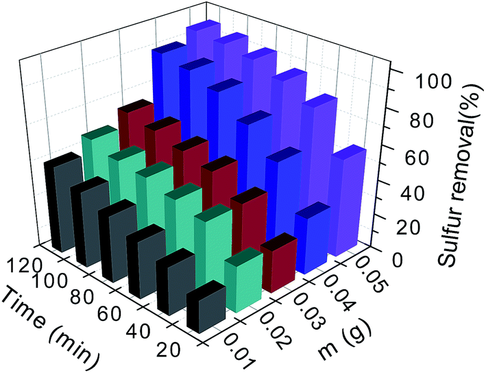
3.10 Effects of catalyst amounts on the removal of 4,6-DMDBT
To optimize the catalytic condition, a series of catalytic experiments were performed. Among all the parameters, catalyst amount is one of the most important factors (Fig. 9). As shown in Fig. 9, the removal rates of 4,6-DMDBT increase with the augment of catalyst amounts. When 0.05 g of catalyst was employed, a 96.07% of sulfur removal was gained within 120 min. Therefore, 0.05 g was selected as a more appropriate catalyst amount of HPMo/BN-IL.
 |
| | Fig. 9 Effect of different catalyst amounts on oxidation of 4,6-DMDBT. Reaction conditions: T = 40 °C, V (oil) = 5 mL, n (O)/n (S) = 4. | |
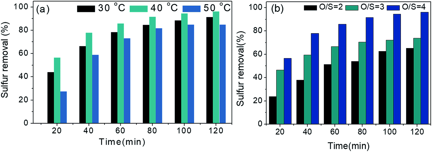
3.11 Effects of temperature and oxidant amounts on oxidation of 4,6-DMDBT
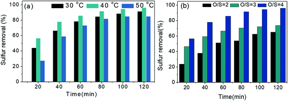
Effects of reaction temperature and oxidant amounts (O/S mole ratio) on oxidizing 4,6-DMDBT were also explored in Fig. 10. As seen from Fig. 10a, the removal rate of 4,6-DMDBT at 40 °C is superior to that at 30 °C. However, when reaction temperature increased to 50 °C, the sulfur removal reduced, owing to that higher temperature can intensify the decomposition of H2O2 (oxidant), causing the distinct decrease in desulfurization rates. Hence, 40 °C was selected as the optimum reaction temperature. Fig. 10b records the removal effect of O/S for oxidation of 4,6-DMDBT. When the O/S mole ratios increased from 2 to 4, the removal rates of 4,6-DMDBT in 120 min were 65.09%, 73.8%, and 96.07%, respectively. Therefore, O/S = 4 is considered as the most suitable mole ratio.
 |
| | Fig. 10 Effects of (a) reaction temperatures and (b) O/S molar rates on oxidation of 4,6-DMDBT. Reaction conditions: (a) V (oil) = 5 mL, m (20% catalyst) = 0.05 g, n (O)/n (S) = 4; (b) T = 40 °C, V (oil) = 5 mL, m (20% catalyst) = 0.05 g. | |
3.12 Effect of different substrates on removal of sulfide
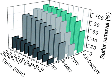
To explore the catalytic performance of HPMo/BN-IL catalyst for various sulfides in fuel, DBT, 4,6-DMDBT, 3-MBT, and BT were selected as substrates. As presented in Fig. 11, the removals of the four substrates all increased with the augment of reaction time. The removal rates of BT in 120 min was only 27.22%, and it could only up to 31.15% with another 60 min. However, the catalyst showed remarkable removal effects for 4,6-DMDBT, DBT, and 3-MBT. The sulfur removals of 4,6-DMDBT, DBT and 3-MBT can improve to 100%, 94.28% and 84.49% with 180 min of reaction time, respectively. In oxidative desulfurization process, when considering the effect of substrates on sulfur removal, electron structure is a determining factor. When regarding the electron density, it not only just indicates the electron density of sulfur atoms (certainly, it is of great importance), but also means that the aromatic properties of the sulfur compound should be considered. When regarding the electron density of sulfur atoms, the electron densities of S atoms in 4,6-DMDBT and DBT are respectively 5.623 and 5.576,62 leading to a higher catalytic activity over 4,6-DMDBT than that over DBT. The electron densities of S atoms in BT and 3-MBT are 5.585 and 5.588, respectively. Thusly, the sulfur removal over BT is lower than that of 3-MBT. However, even though the BT and 3-MBT hold higher S atom electron density, they only have 1 aromatic rings, showing weaker aromatic properties than that of DBT. Both according to our previous reports and considering the catalytic process for heterogeneous catalysis, more aromatic rings of substrates are beneficial to the surface of h-BN based catalysts, which is in favor to the formation of a local high-concentration environment. Thusly, the catalytic activity over DBT is better than those over BT and 3-MBT.
 |
| | Fig. 11 Oxidizing performance of catalyst on the removal of disparate substrates. Experimental conditions: T = 40 °C; V (oil) = 5 mL; m (20% catalyst) = 0.05 g; n (O)/n (S) = 4. | |
3.13 Influence of different distractors on oxidation of 4,6-DMDBT
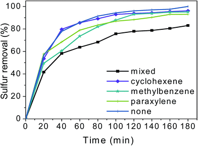
To explore the desulfurization effects of HPMo/BN-IL catalyst for real oils, different distractors containing model oils were employed and the results are shown in Fig. 12. When adding 10 wt% of cyclohexene, the sulfur removal showed slightly decrease. Meanwhile, the sulfur removal also decreased with the addition of 10 wt% of methylbenzene or 10 wt% of paraxylene. However, with a longer reaction time to 180 min, the sulfur removals in methylbenzene or paraxylene model oil could reach 95.11% and 93.06%, respectively. The results manifested that the addition of cyclohexene, methylbenzene or paraxylene has little effects on removal rates of 4,6-DMDBT. Afterwards, a mixture of 10 wt% of cyclohexene, methylbenzene, and paraxylene was added into the 4,6-DMDBT model oil. Fig. 12 illustrates that the sulfur removal of 4,6-DMDBT in a mixed interference oil is significantly lower than that without distractors, but the sulfur removals could still high to 83.05% with a longer reaction time to 180 min.
 |
| | Fig. 12 Influence of different distractors on oxidizing 4,6-DMDBT. Reaction conditions: T = 40 °C; V (oil) = 5 mL; m (20% catalyst) = 0.05 g; n (O)/n (S) = 4. | |
3.14 Recycling performance of HPMo/BN-IL catalyst
Fig. 13 records the recycling effects of 20% HPMo/BN-IL catalyst, to detect the stability of catalyst in ODS system. After the reaction, the reaction system stood for a while to separate oil phase and catalyst phase, then the oil phase was drawn out by a straw. The catalyst phase with a little oil was transferred into an oven for 48 h under 80 °C to dry thoroughly the residual oil and H2O2. Finally, the fresh model oil and H2O2 were added into the regenerated catalyst for the next run. As shown in Fig. 13, the 20% HPMo/BN-IL catalyst can be recycled for 5 times, and the catalyst activity only decreases 3.7% after 5 times. The data present the remarkable recyclability and stability of 20% HPMo/BN-IL catalyst.
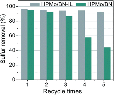 |
| | Fig. 13 Recycling performance of HPMo/BN-IL and HPMo/BN catalysts. Reaction conditions: T = 40 °C; V (oil) = 5 mL; m (20% catalyst) = 0.05 g; n (O)/n (S) = 4. | |
In order to further prove the stability of 20% HPMo/BN-IL catalyst, the recycling activity of 20% HPMo/BN catalyst was also explored by the same methods in Fig. 13. In Fig. 13, the removal rate of 4,6-DMDBT for HPMo/BN-IL catalyst is 92.4% at 5 times of recycling. However, the sulfur removal of 4,6-DMDBT for HPMo/BN drastically decreased to ∼42% of sulfur removal after 5 times of recycling. Therefore, the introduction of IL can improve the stability of HPMo/BN-IL catalyst, making active centers more stable.
3.15 Speculation of catalytic oxidative mechanism
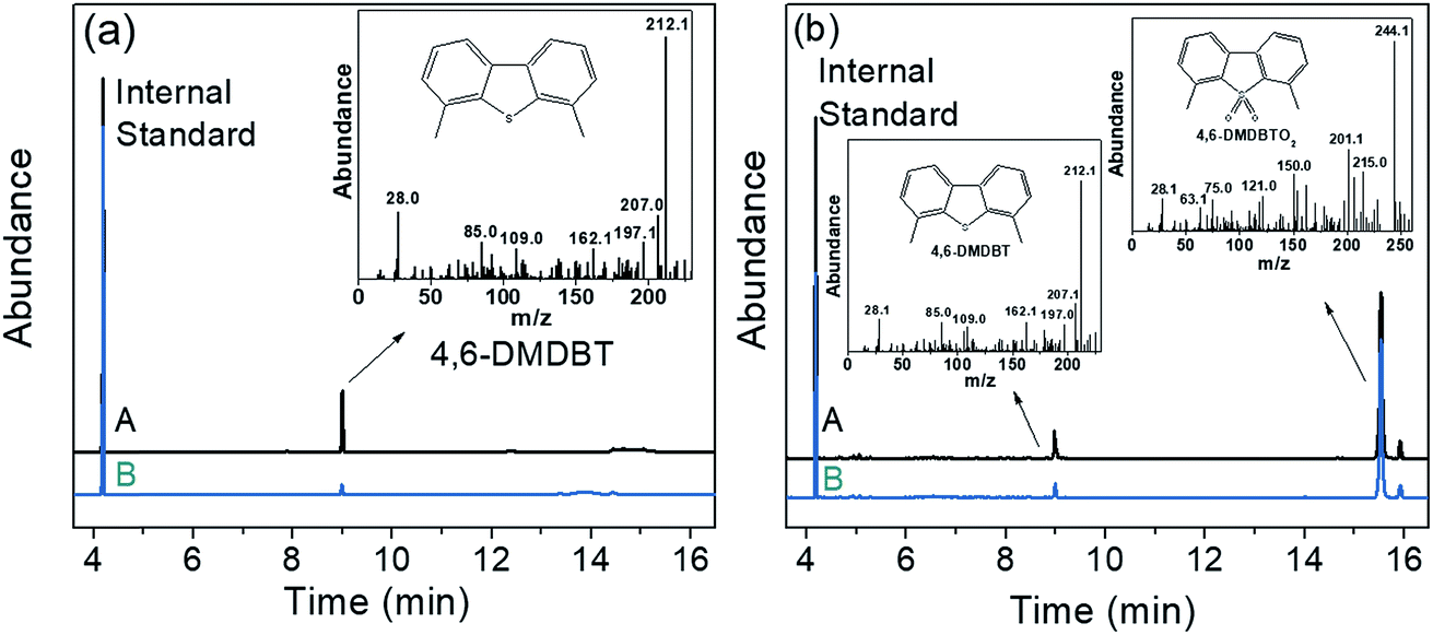
The residual sulfides and reaction products of HPMo/BN-IL system were detected by gas chromatography-mass spectrometry (GC-MS). The detection steps are as follows: after ODS reactions, the reaction liquid was centrifuged to separate upper oil phase and catalyst phase. The upper oil phase was directly detected by GC-MS to analyze residual sulfides and reaction products. While the catalyst phase was re-extracted by CCl4 for further analysis. The GC-MS analysis is shown in Fig. 14. Fig. 14A is the GC-MS spectrogram of the oil phase, the 4,6-DMDBT was detected in oil phase both at 60 min (Fig. 14a-A) and after reaction (Fig. 14a-B), but the peak of 4,6-DMDBT after the reaction is weaker than that at 60 min. Fig. 14B is the GC-MS spectrogram of catalyst phase, as depicted in Fig. 14B, the 4,6-DMDBT and its product of 4,6-DMDBTO2 were observed in catalyst phase at 60 min (Fig. 14b-A) and after reaction (Fig. 14b-B). The result showed that 4,6-DMDBT can be readily adsorbed onto catalysts phase and further oxidized to sulfone for separation.
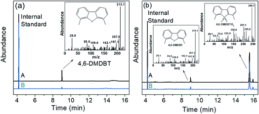 |
| | Fig. 14 GC-MS spectrograms of ODS process (a) oil phase (A) in 60 min and (B) after reaction; (b) catalyst phase (A) in 60 min and (B) after the reaction. | |
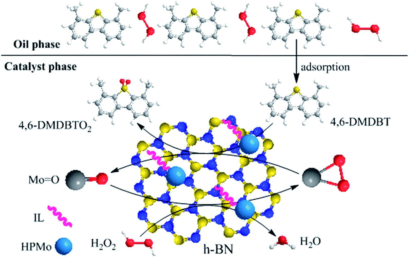
Fig. 15 describes the proposed ODS process of HPMo/BN-IL system, and the specific desulfurization process is as follows: first, 4,6-DMDBT and H2O2 are adsorbed on the surface of catalyst, then H2O2 provides reactive oxygen to MoO groups to form oxygen species Mo(O)2,63,64 and sulfide is oxidized into 4,6-DMDBTO2 by Mo(O)2 to realize desulfurization. Once the 4,6-DMDBT is oxidized into 4,6-DMDBTO2, the catalyst will adsorb sulfides in model oil to keep local high concentration.
 |
| | Fig. 15 The proposed mechanism of HPMo/BN-IL system to removal 4,6-DMDBT. | |
4. Conclusions
In summary, the HPMo is immobilized on the ionic liquid-modified h-BN (BN-IL) to prepare HPMo/BN-IL heterogeneous catalysts. The immobilization process can not only generate a great dispersion of HPMo but also make the active sites more stable. HPMo/BN-IL system showed excellent catalytic activity for DBT, 4,6-DMDBT, and 3-MBT, which can be attributed to the specific surface areas of h-BN, great dispersion of HPMo and unique porous structure. And the introduction of IL can improve the stability of catalyst, which makes HPMo/BN-IL catalyst show better recyclability than HPMo/BN. Reaction conditions, influences of interferents, reaction products, and proposed reaction process are researched in detail.
Conflicts of interest
There are no conflicts to declare.
Acknowledgements
This current work is financially supported by the National Natural Science Foundation of China (No. 21576122, 21507046, 21506083), Six Big Talent Peak in Jiangsu province (JNHB-004), Jiangsu Key Lab of Material Tribology Foundation (No. Kjsmcx201303), University Graduate Student Research and Creative Project of Jiangsu (No. SJLX15_0488).
References
- H. Zhao and G. A. Baker, Front. Chem. Sci. Eng., 2015, 9, 262–279 CrossRef CAS.
- W. S. Zhu, C. Wang, H. P. Li, P. W. Wu, S. H. Xun, W. Jiang, Z. G. Chen, Z. Zhao and H. M. Li, Green Chem., 2015, 17, 2464–2472 RSC.
- R. Menzel, D. Iruretagoyena, Y. Wang, S. M. Bawaked, M. Mokhtar, S. A. Al-Thabaiti, S. N. Basahel and M. S. P. Shaffer, Fuel, 2016, 181, 531–536 CrossRef CAS.
- X. Y. Zeng, X. Y. Xiao, Y. Li, J. Y. Chen and H. L. Wang, Appl. Catal., B, 2017, 209, 98–109 CrossRef CAS.
- X. X. Zhang, W. Zhang, D. Tian, Z. H. Zhou and C. H. Lu, RSC Adv., 2013, 3, 7722 RSC.
- D. H. Wang, N. Liu, J. Y. Zhang, X. Zhao, W. H. Zhang and M. H. Zhang, J. Mol. Catal. A: Chem., 2014, 393, 47–55 CrossRef CAS.
- J. L. García-Gutiérrez, G. C. Laredo, P. García-Gutiérrez and F. Jiménez-Cruz, Fuel, 2014, 138, 118–125 CrossRef.
- J. J. Yuan, J. Xiong, J. H. Wang, W. J. Ding, L. Yang, M. Zhang, W. S. Zhu and H. M. Li, J. Porous Mater., 2016, 23, 823–831 CrossRef CAS.
- H. Xu, Z. Han, D. J. Zhang and C. B. Liu, J. Mol. Catal. A: Chem., 2015, 398, 297–303 CrossRef CAS.
- M. Li, M. Zhang, A. M. Wei, W. S. Zhu, S. H. Xun, Y. N. Li, H. P. Li and H. M. Li, J. Mol. Catal. A: Chem., 2015, 406, 23–30 CrossRef CAS.
- P. W. Wu, S. Z. Yang, W. S. Zhu, H. P. Li, Y. H. Chao, H. Y. Zhu, H. M. Li and S. Dai, Small, 2017, 1701857 CrossRef PubMed.
- C. M. Granadeiro, S. O. Ribeiro, M. Karmaoui, R. Valenca, J. C. Ribeiro, B. de Castro, L. Cunha-Silva and S. S. Balula, Chem. Commun., 2015, 51, 13818–13821 RSC.
- H. Y. Lü, P. C. Li, C. L. Deng, W. Z. Ren, S. N. Wang, P. Liu and H. Zhang, Chem. Commun., 2015, 51, 10703–10706 RSC.
- P. W. Wu, W. S. Zhu, A. M. Wei, B. L. Dai, Y. H. Chao, C. F. Li, H. M. Li and S. Dai, Chem.–Eur. J., 2015, 21, 15421–15427 CrossRef CAS PubMed.
- W. J. Ding, W. S. Zhu, J. Xiong, L. Yang, A. M. Wei, M. Zhang and H. M. Li, Chem. Eng. J., 2015, 266, 213–221 CrossRef CAS.
- C. X. Shi, W. X. Wang, N. Liu, X. Y. Xu, D. H. Wang, M. H. Zhang, P. C. Sun and T. H. Chen, Chem. Commun., 2015, 51, 11500–11503 RSC.
- M. Chamack, A. R. Mahjoub and H. Aghayan, Chem. Eng. J., 2014, 255, 686–694 CrossRef CAS.
- F. L. Yu, C. Y. Liu, B. Yuan, C. X. Xie and S. T. Yu, Catal. Commun., 2015, 68, 49–52 CrossRef CAS.
- F. L. Yu, Q. Y. Wang, B. Yuan, C. X. Xie and S. T. Yu, Chem. Eng. J., 2017, 309, 298–304 CrossRef CAS.
- M. Kooti and E. Nasiri, J. Mol. Catal. A: Chem., 2015, 406, 168–177 CrossRef CAS.
- Y. Chen, Y. Cao, Y. Suo, G. P. Zheng, X. X. Guan and X. C. Zheng, J. Taiwan Inst. Chem. Eng., 2015, 51, 186–192 CrossRef CAS.
- K. V. Avramidou, F. Zaccheria, S. A. Karakoulia, K. S. Triantafyllidis and N. Ravasio, Mol. Catal., 2017, 439, 60–71 CrossRef CAS.
- D. P. Sawant, J. Justus, V. V. Balasubramanian, K. Ariga, P. Srinivasu, S. Velmathi, S. B. Halligudi and A. Vinu, Chem.–Eur. J., 2008, 14, 3200–3212 CrossRef CAS PubMed.
- N. Songsiri, G. L. Rempel and P. Prasassarakich, Mol. Catal., 2017, 439, 41–49 CrossRef CAS.
- Y. Cao, M. R. Lu, J. H. Fang, L. Y. Shi and D. S. Zhang, Chem. Commun., 2017, 53, 7549–7552 RSC.
- M. T. Li, W. S. Zhu, P. F. Zhang, Y. H. Chao, Q. He, B. L. Yang, H. M. Li, A. Borisevich and S. Dai, Small, 2016, 12, 3535–3542 CrossRef CAS PubMed.
- T. T. Li, L. J. Wang, K. Zhang, Y. C. Xu, X. Y. Long, S. J. Gao, R. Li and Y. G. Yao, Small, 2016, 12, 4960–4965 CrossRef CAS PubMed.
- J. J. Liu, R. G. Kutty, Q. S. Zheng, V. Eswariah, S. Sreejith and Z. Liu, Small, 2017, 13, 1602456 CrossRef PubMed.
- W. S. Zhu, Z. L. Wu, G. S. Foo, X. Gao, M. X. Zhou, B. Liu, G. M. Veith, P. W. Wu, K. L. Browning, H. N. Lee, H. M. Li, S. Dai and H. Y. Zhu, Nat. Commun., 2017, 8, 15291 CrossRef PubMed.
- P. W. Wu, W. S. Zhu, Y. H. Chao, J. S. Zhang, P. F. Zhang, H. Y. Zhu, C. F. Li, Z. G. Chen, H. M. Li and S. Dai, Chem. Commun., 2016, 52, 144–147 RSC.
- J. Yin, J. Yu, X. M. Li, J. D. Li, J. X. Zhou, Z. H. Zhang and W. L. Guo, Small, 2015, 11, 4497–4502 CrossRef CAS PubMed.
- C. J. Huang, C. Chen, X. X. Ye, W. Q. Ye, J. L. Hu, C. Xu and X. Q. Qiu, J. Mater. Chem. A, 2013, 1, 12192–12197 CAS.
- C. J. Huang, W. Q. Ye, Q. W. Liu and X. Q. Qiu, ACS Appl. Mater. Interfaces, 2014, 6, 14469–14476 CAS.
- H. Y. Zhu, Z. L. Wu, D. Su, G. M. Veith, H. F. Lu, P. F. Zhang, S. H. Chai and S. Dai, J. Am. Chem. Soc., 2015, 137, 10156–10159 CrossRef CAS PubMed.
- H. Y. Zhu, S. Zhang, Y. X. Huang, L. H. Wu and S. H. Sun, Nano Lett., 2013, 13, 2947–2951 CrossRef CAS PubMed.
- W. S. Zhu, B. L. Dai, P. W. Wu, Y. H. Chao, J. Xiong, S. H. Xun, H. P. Li and H. M. Li, ACS Sustainable Chem. Eng., 2015, 3, 186–194 CrossRef CAS.
- H. Y. Ji, J. Sun, P. W. Wu, B. L. Dai, Y. H. Chao, M. Zhang, W. Jiang, W. S. Zhu and H. M. Li, J. Mol. Catal. A: Chem., 2016, 423, 207–215 CrossRef CAS.
- B. L. Dai, P. W. Wu, W. S. Zhu, Y. H. Chao, J. Sun, J. Xiong, W. Jiang and H. M. Li, RSC Adv., 2016, 6, 140–147 RSC.
- C. C. Tang, Y. Bando, T. Sato and K. Kurashima, Adv. Mater., 2002, 14, 1046–1049 CrossRef CAS.
- J. Xiong, W. S. Zhu, W. J. Ding, L. Yang, Y. H. Chao, H. P. Li, F. X. Zhu and H. M. Li, Ind. Eng. Chem. Res., 2014, 53, 19895–19904 CrossRef CAS.
- W. S. Zhu, W. L. Huang, H. M. Li, M. Zhang, W. Jiang, G. Y. Chen and C. R. Han, Fuel Process. Technol., 2011, 92, 1842–1848 CrossRef CAS.
- F. J. Méndez, A. Llanos, M. Echeverría, R. Jáuregui, Y. Villasana, Y. Díaz, G. Liendo-Polanco, M. A. Ramos-García, T. Zoltan and J. L. Brito, Fuel, 2013, 110, 249–258 CrossRef.
- J. H. Qiu, G. H. Wang, D. L. Zeng, Y. Tang, M. Wang and Y. J. Li, Fuel Process. Technol., 2009, 90, 1538–1542 CrossRef CAS.
- W. W. Lei, D. Portehault, R. Dimova and M. Antoniettit, J. Am. Chem. Soc., 2011, 133, 7121–7127 CrossRef CAS PubMed.
- F. J. Liu, L. Wang, Q. Sun, L. F. Zhu, X. J. Meng and F. S. Xiao, J. Am. Chem. Soc., 2012, 134, 16948–16950 CrossRef CAS PubMed.
- X. J. Wang, W. Y. Yang, F. T. Li, J. Zhao, R. H. Liu, S. J. Liu and B. Li, J. Hazard. Mater., 2015, 292, 126–136 CrossRef CAS PubMed.
- Z. Ai, W. Ho, S. Lee and L. Zhang, Environ. Sci. Technol., 2009, 43, 4143–4150 CrossRef CAS PubMed.
- W. Jiang, D. Zheng, S. H. Xun, Y. J. Qin, Q. Q. Lu, W. S. Zhu and H. M. Li, Fuel, 2017, 190, 1–9 CrossRef CAS.
- T. Sainsbury, A. Satti, P. May, Z. M. Wang, I. McGovern, Y. K. Gun'ko and J. Coleman, J. Am. Chem. Soc., 2012, 134, 18758–18771 CrossRef CAS PubMed.
- W. W. Lei, D. Portehault, D. Liu, S. Qin and Y. Chen, Nat. Commun., 2013, 4, 1777 CrossRef PubMed.
- M. Nakayama, T. Ii and K. Ogura, J. Mater. Res., 2003, 18, 2509–2514 CrossRef CAS.
- X. J. Song, W. C. Zhu, K. G. Li, J. Wang, H. L. Niu, H. C. Gao, W. Gao, W. X. Zhang, J. H. Yu and M. J. Jia, Catal. Today, 2016, 259, 59–65 CrossRef CAS.
- I. Tamiolakis, I. N. Lykakis, A. P. Katsoulidis, M. Stratakis and G. S. Armatas, Chem. Mater., 2011, 23, 4204–4211 CrossRef CAS.
- W. Jiang, D. Zheng, S. Xun, Y. Qin, Q. Lu, W. Zhu and H. Li, Fuel, 2017, 190, 1–7 CrossRef CAS.
- Y. Kubota, K. Watanabe, O. Tsuda and T. Taniguchi, Science, 2007, 317, 932–934 CrossRef CAS PubMed.
- V. Balaga, J. Pedada, H. B. Friedrich and S. Singh, J. Mol. Catal. A: Chem., 2016, 425, 116–123 CrossRef CAS.
- B. Viswanadham, J. Pedada, H. B. Friedrich and S. Singh, Catal. Lett., 2016, 146, 1470–1477 CrossRef CAS.
- B. Viswanadham, A. Srikanth and K. V. R. Chary, J. Chem. Sci., 2014, 126, 445–454 CrossRef CAS.
- B. Viswanadham, P. Jhansi, K. V. R. Chary, H. B. Friedrich and S. Singh, Catal. Lett., 2015, 146, 364–372 CrossRef.
- H. Aliyan, R. Fazaeli and N. Habibollahi, J. Korean Chem. Soc., 2012, 56, 591–596 CrossRef CAS.
- Y. Ding, B. C. Ma, Q. Gao, G. X. Li, L. Yan and J. S. Suo, J. Mol. Catal. A: Chem., 2005, 230, 121–128 CrossRef CAS.
- H. P. Li, W. S. Zhu, S. W. Zhu, J. X. Xia, Y. H. Chang, W. Jiang, M. Zhang, Y. W. Zhou and H. M. Li, AIChE J., 2016, 62, 2087–2100 CrossRef CAS.
- J. Zhang, A. Wang, Y. J. Wang, H. Y. Wang and J. Z. Gui, Chem. Eng. J., 2014, 245, 65–70 CrossRef CAS.
- J. L. García-Gutiérrez, G. A. Fuentes, M. E. Hernández-Terán, P. García, F. Murrieta-Guevara and F. Jiménez-Cruz, Appl. Catal., A, 2008, 334, 366–373 CrossRef.
Footnote |
| † Electronic supplementary information (ESI) available. See DOI: 10.1039/c7ra10697a |
|
| This journal is © The Royal Society of Chemistry 2017 |
Click here to see how this site uses Cookies. View our privacy policy here. 
 Open Access Article
 This Open Access Article is licensed under a
  c,
Jia Suna,
Yanhong Chao
c,
Jia Suna,
Yanhong Chao