DOI:
10.1039/C7RA10215A
(Paper)
RSC Adv., 2017,
7, 51001-51007
Aqueous synthesis of highly fluorescent and stable Cu–In–S/ZnS core/shell nanocrystals for cell imaging†
Received
14th September 2017
, Accepted 27th October 2017
First published on 2nd November 2017
Abstract
Ternary I–III–VI nanocrystals (NCs) without toxic elements, such as Cu–In–S, are promising candidates for biolabeling and bioimaging due to their favorable biocompatibility. At present, it remains a tremendous challenge to directly synthesize high-quality Cu–In–S/ZnS core/shell NCs in aqueous solution at atmospheric pressure. Herein, a simple and reliable strategy that combines the hot-injection method and successive ion layer adsorption and reaction has been proposed to realize aqueous synthesis of fluorescent Cu–In–S/ZnS core/shell NCs. The growth of ZnS shell around Cu–In–S NCs not only improved the fluorescence quantum yield by several hundred times and to the value of 18%, but also effectively enhanced their fluorescence stability by protecting Cu+ in Cu–In–S core from being oxidized to Cu2+. The prepared Cu–In–S/ZnS core/shell NCs with bright and stable fluorescence were conjugated with wheat germ agglutinin and further applied to cancer cell imaging. This strategy here should open new avenues for aqueous synthesis of high-quality nanomaterials with the core/shell structure for broad biomedical applications.
1. Introduction
Semiconductor nanocrystals (NCs), also called quantum dots (QDs), have been extensively investigated in the last two decades because of their unique optical properties, such as size-tunable fluorescence (FL), narrow emission peak, broad excitation spectrum, simultaneous excitation of multicolored QDs at a single wavelength, and excellent photostability.1–3 They have served as good signal reporters for biolabeling and ideal contrast agents for cell imaging and in vivo cancer targeted imaging.4–7 However, most of the currently used QDs contain toxic elements, such as class A elements (Cd, Pb, and Hg) and class B elements (Se, Te, and As), which will cause unfavorable biotoxicity after released from the biodegraded QDs and hinder their potential clinical applications.8–11 Thus, it is highly desired to develop novel biocompatible QDs as safe probes for their widespread biological application.12–15
Copper indium sulfide (Cu–In–S) NCs are promising candidates as low-toxicity QDs. Pons et al. have demonstrated a much reduced in vivo local acute toxicity of CuInS2/ZnS NCs compared to CdTeSe/CdZnS QDs by studying QD-induced lymph node inflammation.16 In addition, the FL emission of Cu–In–S NCs could be tuned in the visible and near-infrared regions by tailoring the composition.17,18 Due to the small lattice mismatch between ZnS and Cu–In–S of 2.2%,19,20 ZnS is commonly used as the shell material to improve the quantum yields (QYs) and enhance the photostability of Cu–In–S NCs. Up to now, the main strategies for synthesizing Cu–In–S/ZnS core/shell NCs were thermal decomposition of mixed precursor solution,21–23 the hot-injection strategy,24 and the cation exchange reaction.25,26 However, these syntheses were usually carried out at a high reaction temperature in organic solvents, which were contrary to the requirement of green and low-cost synthesis. Moreover, the obtained Cu–In–S/ZnS core/shell NCs have hydrophobic surface and need to be transferred to the aqueous phase prior to biomedical applications, which will result in a significant size increase and a decrease of FL intensity.20,27,28 The subsequently developed hydrothermal approach could realize the synthesis of hydrophilic Cu–In–S NCs, and avoid additional water solubilization. But the reaction should be performed in an airtight autoclave for a long time up to 21 h.29,30 In addition to be risky and time-consuming, this method is not a good choice to prepare Cu–In–S/ZnS core/shell NCs.31 Compared with the above synthetic methods, directly synthesizing Cu–In–S/ZnS core/shell NCs in aqueous solution at atmospheric pressure is much simpler, greener, and cheaper. To the best of our knowledge, there are only a few reports about that, in which the FL QY and FL stability of Cu–In–S/ZnS core/shell NCs need to be comprehensively studied and further improved.32,33
In this work, we have presented a simple and reliable strategy to prepare hydrophilic Cu–In–S/ZnS core/shell NCs with bright and stable FL in aqueous solution at atmospheric pressure (Scheme 1). In the two-step procedure, first Cu–In–S NCs were prepared by injecting Na2S solution into the mixture of CuI, InCl3, and glutathione at 90 °C. The resulting Cu–In–S NCs were subsequently overcoated with a ZnS shell via successive ion layer adsorption and reaction, which is favorable for homogeneous growth of shell precursors onto all core NCs in solution.34–37 During the shell growth, the FL QY strongly increased by several hundred times and to the value of 18%, which is comparable to that of hydrophilic Cu–In–S/ZnS NCs obtained through a water solubilization process in some previous reports.28,38 For the first time it was found that the ZnS shell could protect Cu+ in the Cu–In–S core from being oxidized to Cu2+, and subsequently enhance their FL stability. Finally, the prepared Cu–In–S/ZnS core/shell NCs were conjugated with wheat germ agglutinin (WGA) and successfully applied to cancer cell imaging.
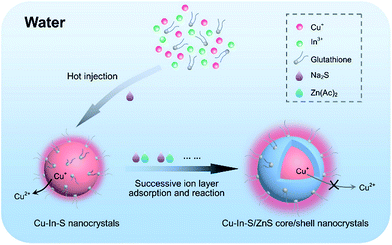 |
| | Scheme 1 Strategy for directly synthesizing high-quality Cu–In–S/ZnS core/shell NCs in aqueous solution at atmospheric pressure. | |
2. Experimental
2.1 Materials
Copper(I) iodide (CuI, 99.95% metals basis), indium(III) chloride tetrahydrate (InCl3·4H2O, 99.9% metals basis), glutathione (reduced), zinc acetate (Zn(Ac)2, 99.99%), and rhodamine 6G (R6G) were purchased from aladdin. N-(3-dimethylaminopropyl)-N′-ethylcarbodiimide hydrochloride (EDC·HCl, commercial grade) was purchased from Sigma-Aldrich. 3-(4,5-Dimethyl-2-thiazolyl)-2,5-diphenyl-2-H-tetrazolium bromide (MTT) was purchased from Amresco. WGA and FITC-labeled WGA (FITC–WGA) were purchased from Vector. Sodium sulfide nonahydrate (Na2S·9H2O), ethanol, dimethyl sulfoxide (DMSO), and sodium hydrate (NaOH) were purchased from China National Pharmaceutical Group Corporation.
2.2 Synthesis of Cu–In–S NCs
For a typical synthetic reaction, 0.1 mmol of CuI, 0.2 mmol of InCl3·4H2O, 1 mmol of glutathione, and 10 mL of deionized water were loaded into a three-neck flask filled with argon. The pH of the reaction mixture was adjusted to 9.0 by stepwise addition of NaOH solution. When heated to 90 °C, this mixture became clear and colorless. At this moment, the Na2S solution (0.2 M, 1 mL) was swiftly injected into the reaction mixture under vigorous stirring. The color of reaction solution immediately turned from colorless to orange. Subsequently, the reaction mixture was maintained at the temperature of 80 °C for 30 min. Then the solution was cooled down to room temperature. The products were precipitated by adding excess ethanol and centrifugation (8000 g) for 5 min. The precipitated NCs were purified via centrifugal filtration with centrifugal filter devices with the MWCO of 10 kDa and finally dispersed in deionized water for further characterizations.
2.3 In situ synthesis of Cu–In–S/ZnS core/shell NCs
The freshly prepared Cu–In–S NCs were directly employed to in situ synthesize Cu–In–S/ZnS core/shell NCs without any purification. The Na2S solution (0.2 M, 1 mL) and the Zn precursor solution prepared by dissolving 0.2 mmol of Zn(Ac)2 and 100 mg of glutathione in 1.5 mL of deionized water were added dropwise into Cu–In–S NCs. The above procedure was repeated 5 times, and each growth lasted 30 minutes. The obtained Cu–In–S/ZnS NCs were precipitated by adding excess ethanol and centrifugation (8000 g) for 5 min. The precipitate was purified via centrifugal filtration with centrifugal filter devices with the MWCO of 10 kDa and finally dried under vacuum into the powder for further experiments.
2.4 Characterization
Transmission electron microscopy (TEM) images were obtained on a JEOL JEM-2100 transmission electron microscope operated at 200 kV. Samples for TEM characterization were prepared by dropping the solution of NCs on an ultrathin-carbon-coated Ni grid and allowing the sample to dry. Powder X-ray diffraction (XRD) pattern was obtained on a Bruker D8 Advanced X-ray diffractometer (Bruker axs) using Cu Kα radiation (wavelength 1.5406 Å). X-ray photoelectron spectroscopy (XPS) spectra were collected on a VG Multilab 2000 X-ray photoelectron spectrometer. Fourier transform infrared (FT-IR) analysis was conducted using pressed KBr pellets with a Thermo Scientific Nicolet iS10 spectrometer. Absorption spectra in the wavelength range of 400–700 nm were recorded with a Shimadzu UV-2550 spectrophotometer. FL emission spectra were measured at the excitation wavelength of 450 nm on a PerkinElmer LS55 FL spectrophotometer. The FL QY of the sample was determined by comparison with R6G as the standard.
2.5 Conjugation of Cu–In–S/ZnS core/shell NCs with WGA
The purified Cu–In–S/ZnS core/shell NCs were incubated with EDC·HCl and WGA at the molar ratio of 1![[thin space (1/6-em)]](https://www.rsc.org/images/entities/char_2009.gif) :2000:10 at 25 °C for 2 h. The products were purified by gel filtration on polypropylene columns (PIERCE) with the medium of Superdex 200 prep grade (GE Healthcare). Agarose gel electrophoresis of the products was performed on a DYY-6D gel electrophoresis apparatus (Beijing Liu Yi instrument factory) by using 1% (w/v) agarose gel, and the gel was imaged on alphaimager HP system (Alpha Innotech).
:2000:10 at 25 °C for 2 h. The products were purified by gel filtration on polypropylene columns (PIERCE) with the medium of Superdex 200 prep grade (GE Healthcare). Agarose gel electrophoresis of the products was performed on a DYY-6D gel electrophoresis apparatus (Beijing Liu Yi instrument factory) by using 1% (w/v) agarose gel, and the gel was imaged on alphaimager HP system (Alpha Innotech).
2.6 MTT assay
Human tongue squamous cell carcinoma CAL-27 cells were purchased from China Center for Type Culture Collection (Wuhan, P. R. China). CAL-27 cells resuspended in DMEM culture medium were seeded into a 96-well plate at a density of 7000 cells per well and cultured overnight for cell attachment. Then the medium was replaced with 200 μL of fresh medium containing different concentration of Cu–In–S/ZnS NCs (0, 5, 12.5, 25, 50, 100 μg mL−1). After incubation for 24 h, the cells in each well were washed once with phosphate buffered saline (1 × PBS) and incubated with the mixture of 180 μL of 1 × PBS and 20 μL of MTT solution (5 mg mL−1) for another 4 h. Then the medium in the 96-well plate was removed, and DMSO (150 μL) was added into each well, followed by gentle shaking for 10 min. The optical density of each well at 570 nm was recorded using a microplate spectrophotometer (MULTISKAN MK3, Thermo Scientific).
2.7 Cell imaging
CAL-27 cells cultured in a 6-well plate were exposed to 1 × PBS containing 5% (w/v) bovine serum albumin (BSA) for 30 min, and then incubated with FITC, FITC–WGA, Cu–In–S/ZnS NCs, or WGA-modified Cu–In–S/ZnS NCs at 37 °C for 1.5 h. Subsequently, the cells were washed with 1% (w/v) BSA. FL images were recorded with a CCD camera (Nikon DS-Ri1) mounted on an inverted FL microscope (Ti–U, Nikon, Japan), and analyzed with the Image-Pro Plus 6.0 software.
3. Results and discussion
3.1 Synthesis and characterization of Cu–In–S NCs and Cu–In–S/ZnS core/shell NCs
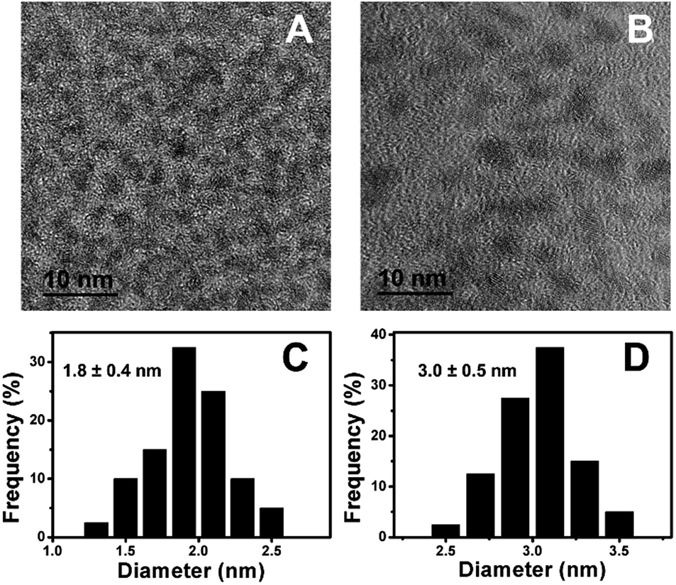
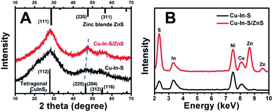
Fig. 1A showed the TEM image of Cu–In–S NCs, from which we can see that the Cu–In–S NCs were small well-dispersed spherical particles. Their size was measured to be 1.8 ± 0.4 nm by analyzing 100 particles (Fig. 1C). The crystal structure of Cu–In–S NCs was characterized by XRD analysis, as shown in Fig. 2A (black line). The very broad diffraction peaks of Cu–In–S NCs were observed because of the small size of the particles, which can be indexed to the tetragonal crystal structure of CuInS2 chalcopyrite.39 Energy-dispersive X-ray (EDX) result (Fig. 2B, black line) confirmed the presence of Cu, In, and S elements in the products. It should be pointed out that the Ni element in the EDX spectrum arose from Ni grid used in the preparation of TEM sample, on which the solution of NCs was dropped. FT-IR spectrum of Cu–In–S NCs (Fig. S1 in the ESI†) demonstrated that thiol groups in glutathione have covalently bound with metal atoms on the surface of Cu–In–S NCs. Thus, it could be concluded that Cu–In–S NCs capped with glutathione have been successfully prepared.
 |
| | Fig. 1 TEM image (A) and the corresponding size histogram (C) of Cu–In–S NCs. TEM image (B) and the corresponding size histogram (D) of Cu–In–S/ZnS core/shell NCs. | |
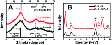 |
| | Fig. 2 XRD patterns (A) and EDX spectra (B) of Cu–In–S NCs and Cu–In–S/ZnS core/shell NCs. | |
To in situ coat Cu–In–S NCs with ZnS shell, successive ion layer adsorption and reaction has been employed, in which Zn precursor and S precursor were added dropwise into freshly prepared Cu–In–S NCs by turns. Firstly, the adding sequence of Zn and S precursors was studied. As shown in Fig. S2 in the ESI,† the products obtained by introducing S precursor and then Zn precursor exhibited stronger FL than that with the adding sequence of first Zn and then S precursors. It may be related to the metal-atoms-rich surface of Cu–In–S NCs with ligand of glutathione. The added S precursor could tightly bind to the metal atoms on the surface of Cu–In–S NCs as well as facilitate the subsequent Zn adsorption. Thus, the growth of ZnS shell was performed by adding S precursor and then Zn precursor into Cu–In–S NCs. When the adding of ZnS shell precursor solution was repeated five times, the FL intensity of products no longer increased (Fig. S3 in the ESI†). The as-prepared Cu–In–S/ZnS NCs underwent the characterizations of morphology, structure, and element composition. Compared with the Cu–In–S core size, the core/shell particle size of 3.0 ± 0.5 nm (Fig. 1B and D) has increased by 1.2 nm, which is about the thickness of two monolayers of ZnS shell (one monolayer ca. 0.31 nm).40 In Fig. 2A, XRD peaks of Cu–In–S/ZnS NCs shifted to higher angles toward those of the standard zinc blende ZnS. This shift of XRD peaks is usually employed to confirm the formation of core/shell structure.41,42 In the EDX spectrum (Fig. 2B, red line), Zn element was detected for Cu–In–S/ZnS NCs. Above all, the increase of particle size, the shift of XRD pattern to the standard ZnS peaks, and the detection of Zn element confirmed the formation of ZnS shell around the Cu–In–S NCs to obtain Cu–In–S/ZnS core/shell NCs.
3.2 Effect of ZnS shell on FL intensity and stability of Cu–In–S NCs
Fig. 3 showed the absorption and FL emission spectra of Cu–In–S NCs before and after the growth of ZnS shell. With the deposition of the ZnS shell upon the Cu–In–S core, the shoulder peak at around 450 nm disappeared, leaving no obvious absorption peak. In Fig. 3A, the FL of Cu–In–S core was too weak to be quantified, which may be caused by surface defects-related nonradiative recombination. The ZnS shell overcoating resulted in a slight shift of FL emission wavelength from 635 nm to 629 nm and a dramatic improvement of FL intensity by several hundred-fold (Fig. 3B), which is associated with a reduction in the nonradiative recombination dynamics due to the elimination of surface trap states by the ZnS shell. The FL QY of Cu–In–S/ZnS core/shell NCs was measured to be 18% with R6G as the reference (Fig. S4 in the ESI†), which could meet the demand of bioimaging. It was also found that the FL emission wavelength of Cu–In–S/ZnS NCs could be tuned by varying the Cu/In raw ratios. As shown in Fig. S5 in the ESI,† when the Cu/In raw ratio was changed to 1:4 and to 1:1, the FL wavelength of Cu–In–S/ZnS NCs shifted to 608 nm and to 660 nm, respectively. With the increase of Cu/In raw ratios, the FL wavelength of Cu–In–S/ZnS NCs exhibited a red shift.
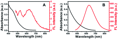 |
| | Fig. 3 Absorption and FL emission spectra of Cu–In–S NCs (A) and Cu–In–S/ZnS core/shell NCs (B). | |
In addition to improving the FL brightness of Cu–In–S NCs, the growth of ZnS shell also has an effect on their photostability and chemical stability. So far, there are very few reports on studying the stability of hydrophilic Cu–In–S NCs directly prepared in aqueous solution. Firstly, the photostability of Cu–In–S core and Cu–In–S/ZnS core/shell NCs was examined by monitoring their FL intensity change under light irradiation. As shown in Fig. 4A, the originally weak FL of Cu–In–S NCs decrease dramatically after continuous illumination with 50 W mercury lamp, and less than 10% of FL could be retained after 90 min. However, Cu–In–S/ZnS core/shell NCs were more stable and preserved 90% of FL after irradiation for 150 min. Thus, the growth of ZnS shell has endowed Cu–In–S NCs with the property of photobleaching resistance. Besides, an interesting result in XPS analyses of freshly prepared Cu–In–S NCs and Cu–In–S/ZnS core/shell NCs has attracted our attention and promoted us to study their chemical stability. As shown in Fig. 5B and F, the Cu element in freshly prepared Cu–In–S NCs existed in two forms of Cu+ and Cu2+, while only Cu+ existed in freshly prepared Cu–In–S/ZnS core/shell NCs. According to the previous reports, the Cu element of Cu–In–S NCs is usually in the +1 valence.18,43,44 Since the used Cu precursor in the synthesis was Cu(I) halides CuI, it can be deduced that Cu+ ions in the plain Cu–In–S NCs were very easily oxidized to Cu2+ even in the short period from synthesis, to XPS sample preparation, and finally to XPS measurement. To verify the above deduction, we continued to observe the state of the solutions containing Cu–In–S NCs or Cu–In–S/ZnS core/shell NCs. After stored at 4 °C for 15 days, the Cu–In–S solution has been layered (Fig. 4B). Lots of dark green precipitates appeared, and the supernatant turned out to be blue, which was caused by Cu2+ ions. Whereas Cu–In–S/ZnS core/shell NCs have maintained good dispersibility and exhibited no FL intensity change during the storage for one month (Fig. 4C). These results confirmed that the ZnS shell could protect Cu+ ions in the Cu–In–S core from being oxidized by oxidizing species such as dissolved oxygen, and subsequently enhance their chemical stability. Above all, the stability of Cu–In–S/ZnS core/shell NCs, including photostability and chemical stability, is superior to that of Cu–In–S NCs.
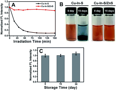 |
| | Fig. 4 (A) FL intensity change of Cu–In–S NCs and Cu–In–S/ZnS core/shell NCs after continuous illumination with 50 W mercury lamp. (B) Pictures of Cu–In–S NCs and Cu–In–S/ZnS core/shell NCs when freshly prepared and after stored at 4 °C for 15 days. (C) FL intensity change of Cu–In–S/ZnS core/shell NCs stored at 4 °C for one month. | |
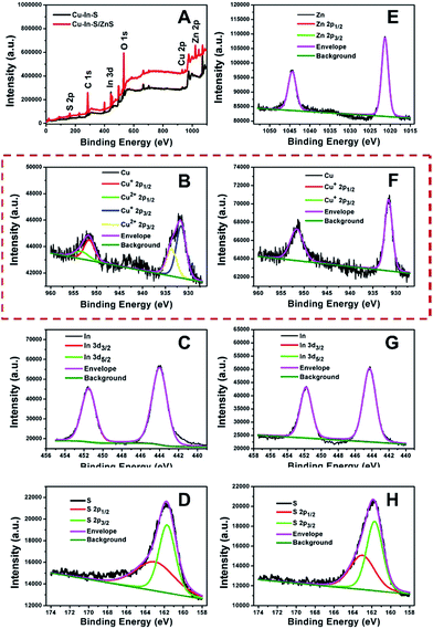 |
| | Fig. 5 (A) XPS survey spectra of Cu–In–S NCs and Cu–In–S/ZnS core/shell NCs. High-resolution XPS spectra of Cu 2p (B), In 3d (C), and S 2p (D) in Cu–In–S NCs. High-resolution XPS spectra of Zn 2p (E), Cu 2p (F), In 3d (G), and S 2p (H) in Cu–In–S/ZnS core/shell NCs. | |
3.3 Cell imaging with Cu–In–S/ZnS core/shell NCs
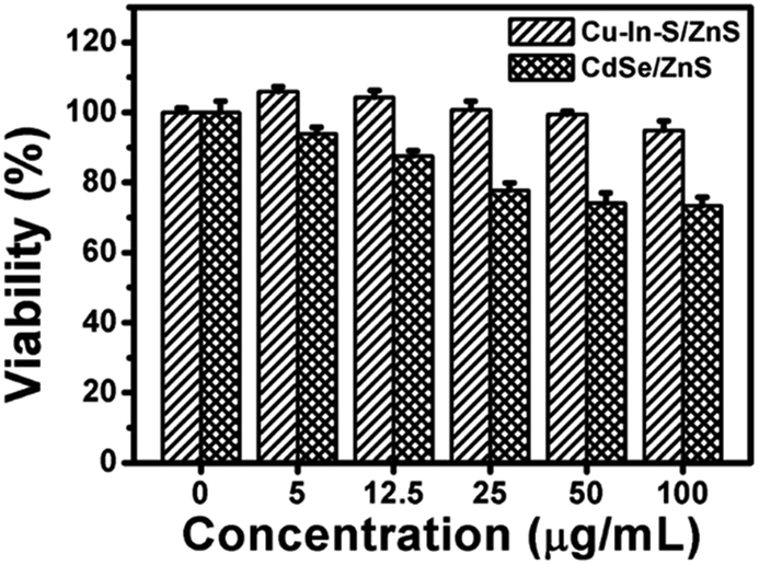
In order to verify the good biocompatibility of Cu–In–S/ZnS core/shell NCs, the cytotoxicity of Cu–In–S/ZnS NCs was compared with that of CdSe/ZnS QDs by using MTT assay with CAL-27 cells as the model cell line. The cells were treated with Cu–In–S/ZnS NCs and CdSe/ZnS QDs of different concentrations from 0 to 100 μg mL−1 for 24 h. As shown in Fig. 6, approximately 95% of CAL-27 cells retained viability after exposed to Cu–In–S/ZnS NCs with the concentration up to 100 μg mL−1, while the viability of CAL-27 cells significantly decreased with the increasing concentration of CdSe/ZnS QDs and only 70% of CAL-27 cells could survive at the concentration of 100 μg mL−1. The above results indicated that the cytotoxicity of Cu–In–S/ZnS NCs was much lower than that of CdSe/ZnS QDs. Thus, Cu–In–S/ZnS core/shell NCs could serve as biocompatible biomaterials.
 |
| | Fig. 6 MTT assays of CAL-27 cells after treated with Cu–In–S/ZnS NCs and CdSe/ZnS QDs of different concentrations from 0 to 100 μg mL−1 for 24 h. | |
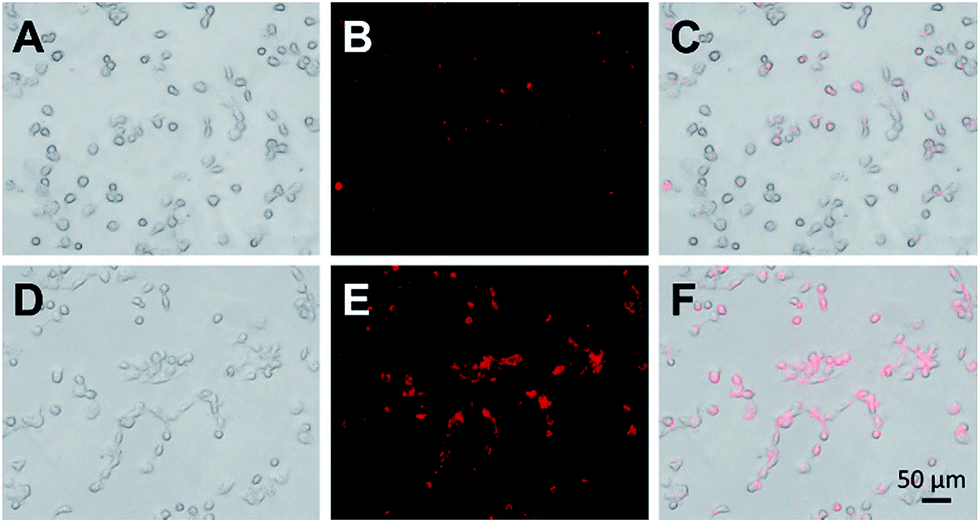
To determine the potential of these bright and stable Cu–In–S/ZnS NCs as optical probes for bioimaging, Cu–In–S/ZnS NCs were conjugated with WGA and then applied for FL imaging of CAL-27 cells. WGA, a kind of immunogenic lectin, could recognize some types of cancer cells by specifically binding to WGA receptors, such as N-acetylglucosamine (GlcNAc) and sialic acid, which are over expressed on the surface plasma membranes of cancer cells. High expression level of WGA receptors on the membrane of CAL-27 cells has been characterized by immunofluorescence assays (Fig. S6 in the ESI†). Then WGA was covalently attached to the surface of Cu–In–S/ZnS NCs via the interaction between amino groups and carboxyl groups to produce WGA-modified Cu–In–S/ZnS NCs. Compared to Cu–In–S/ZnS NCs, WGA-modified Cu–In–S/ZnS NCs moved more slowly in the electric field, confirming the successful conjugation of Cu–In–S/ZnS NCs with WGA (Fig. S7 in the ESI†). Fig. 7 showed the results of CAL-27 cells imaging with Cu–In–S/ZnS NCs and WGA-modified Cu–In–S/ZnS NCs. With regard to the images of Cu–In–S/ZnS NCs, only a weak red FL could be observed, indicating that only little Cu–In–S/ZnS NCs entered CAL-27 cells. However, WGA-modified Cu–In–S/ZnS NCs in CAL-27 cells exhibited strong red FL. Indeed, the presence of WGA on the surface of Cu–In–S/ZnS NCs can facilitate their cellular uptake by CAL-27 cells with high expression of WGA receptors. The results showed the great potential of Cu–In–S/ZnS NCs as biolabels for cancer cell FL imaging.
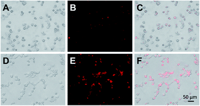 |
| | Fig. 7 Bright-field images, FL images, and the merged images of CAL-27 cells after the incubation with Cu–In–S/ZnS NCs (A–C) and WGA-modified Cu–In–S/ZnS NCs (D–F). | |
4. Conclusions
In summary, we have developed a simple and reliable strategy that combines the hot-injection method and successive ion layer adsorption and reaction to directly prepare highly fluorescent Cu–In–S/ZnS core/shell NCs in aqueous solution. This strategy has effectively avoided high temperatures, high pressures, and the use of organic solvents and expensive raw materials, which meets the requirement of green and low-cost synthesis. The Cu–In–S/ZnS core/shell NCs prepared by this approach showed strong FL, and their QY with value of 18% was comparable to that of hydrophilic Cu–In–S/ZnS NCs obtained through a water solubilization process. We also found for the first time that the ZnS shell could protect Cu+ in Cu–In–S NCs from being oxidized to Cu2+, and significantly enhance the FL stability of Cu–In–S NCs. The prepared Cu–In–S/ZnS core/shell NCs with bright and stable FL were conjugated with WGA and successfully applied to CAL-27 cells imaging. Moreover, this aqueous synthesis method can be extended to aqueous synthesis of other high-quality nanomaterials with the core/shell structure for broad biomedical applications.
Conflicts of interest
There are no conflicts to declare.
Acknowledgements
This work was supported by Wuhan Morning Light Plan of Youth Science and Technology (No. 2017050304010322), the National Nature Science Foundation of China (No. 61501526 and 61178087), and the Fundamental Research Funds for the Central Universities, South-Central University for Nationalities (No. CZQ16011, CZZ17007, and CZY14017).
References
- W. C. W. Chan and S. M. Nie, Science, 1998, 281, 2016–2018 CrossRef CAS PubMed.
- I. L. Medintz, H. T. Uyeda, E. R. Goldman and H. Mattoussi, Nat. Mater., 2005, 4, 435–446 CrossRef CAS PubMed.
- K. D. Wegner and N. Hildebrandt, Chem. Soc. Rev., 2015, 44, 4792–4834 RSC.
- S. L. Liu, Z. G. Wang, Z. L. Zhang and D. W. Pang, Chem. Soc. Rev., 2016, 45, 1211–1224 RSC.
- E. Z. Sun, A. A. Liu, Z. L. Zhang, S. L. Liu, Z. Q. Tian and D. W. Pang, ACS Nano, 2017, 11, 4395–4406 CrossRef CAS PubMed.
- Z. Y. Hong, C. Lv, A. A. Liu, S. L. Liu, E. Z. Sun, Z. L. Zhang, A. W. Lei and D. W. Pang, ACS Nano, 2015, 9, 11750–11760 CrossRef CAS PubMed.
- C. N. Zhu, G. Chen, Z. Q. Tian, W. Wang, W. Q. Zhong, Z. Li, Z. L. Zhang and D. W. Pang, Small, 2017, 13, 1602309 CrossRef PubMed.
- S. J. Cho, D. Maysinger, M. Jain, B. Röder, S. Hackbarth and F. M. Winnik, Langmuir, 2007, 23, 1974–1980 CrossRef CAS PubMed.
- J. L. Pelley, A. S. Daar and M. A. Saner, Toxicol. Sci., 2009, 112, 276–296 CrossRef CAS PubMed.
- F. M. Winnik and D. Maysinger, Acc. Chem. Res., 2013, 46, 672–680 CrossRef CAS PubMed.
- M. Vinceti, E. T. Wei, C. Malagoli, M. Bergomi and G. Vivoli, Rev. Environ. Health, 2001, 16, 233–251 CAS.
- Y. P. Gu, R. Cui, Z. L. Zhang, Z. X. Xie and D. W. Pang, J. Am. Chem. Soc., 2012, 134, 79–82 CrossRef CAS PubMed.
- C. N. Zhu, P. Jiang, Z. L. Zhang, D. L. Zhu, Z. Q. Tian and D. W. Pang, ACS Appl. Mater. Interfaces, 2013, 5, 1186–1189 CAS.
- Y. F. Wang, Y. W. Zhu, S. M. Yu and C. L. Jiang, RSC Adv., 2017, 7, 40973–40989 RSC.
- Z. T. Fan, S. H. Li, F. L. Yuan and L. Z. Fan, RSC Adv., 2015, 5, 19773–19789 RSC.
- T. Pons, E. Pic, N. Lequeux, E. Cassette, L. Bezdetnaya, F. Guillemin, F. Marchal and B. Dubertret, ACS Nano, 2010, 4, 2531–2538 CrossRef CAS PubMed.
- B. K. Chen, H. Z. Zhong, W. Q. Zhang, Z. A. Tan, Y. F. Li, C. R. Yu, T. Y. Zhai, Y. S. Bando, S. Y. Yang and B. S. Zou, Adv. Funct. Mater., 2012, 22, 2081–2088 CrossRef CAS.
- Y. Y. Chen, S. J. Li, L. J. Huang and D. C. Pan, Nanoscale, 2014, 6, 1295–1298 RSC.
- D. C. Pan, D. Weng, X. L. Wang, Q. F. Xiao, W. Chen, C. L. Xu, Z. Z. Yang and Y. F. Lu, Chem. Commun., 2009, 4221–4223 RSC.
- D. W. Deng, Y. Q. Chen, J. Cao, J. M. Tian, Z. Y. Qian, S. Achilefu and Y. Q. Gu, Chem. Mater., 2012, 24, 3029–3037 CrossRef CAS.
- L. Li, A. Pandey, D. J. Werder, B. P. Khanal, J. M. Pietryga and V. I. Klimov, J. Am. Chem. Soc., 2011, 133, 1176–1179 CrossRef CAS PubMed.
- Y. H. Jia, H. C. Wang, Z. R. Yan, L. Deng, H. Dong, N. Ma and D. B. Sun, RSC Adv., 2016, 6, 93303–93308 RSC.
- Y. S. Kim, Y. Lee, Y. Kim, D. Kim, H. S. Choi, J. C. Park, Y. S. Nam and D. Y. Jeon, RSC Adv., 2017, 7, 10675–10682 RSC.
- R. G. Xie, M. Rutherford and X. G. Peng, J. Am. Chem. Soc., 2009, 131, 5691–5697 CrossRef CAS PubMed.
- J. Park and S.-W. Kim, J. Mater. Chem., 2011, 21, 3745–3750 RSC.
- C. H. Xia, J. D. Meeldijk, H. C. Gerritsen and C. de Mello Donegá, Chem. Mater., 2017, 29, 4940–4951 CrossRef CAS PubMed.
- L. Li, T. J. Daou, I. Texier, T. T. K. Chi, N. Q. Liem and P. Reiss, Chem. Mater., 2009, 21, 2422–2429 CrossRef CAS.
- K. Yu, P. Ng, J. Y. Ouyang, M. B. Zaman, A. Abulrob, T. N. Baral, D. Fatehi, Z. J. Jakubek, D. Kingston, X. H. Wu, X. Y. Liu, C. Hebert, D. M. Leek and D. M. Whitfield, ACS Appl. Mater. Interfaces, 2013, 5, 2870–2880 CAS.
- S. Y. Liu, H. Zhang, Y. Qiao and X. G. Su, RSC Adv., 2012, 2, 819–825 RSC.
- S. Y. Liu, F. P. Shi, X. J. Zhao, L. Chen and X. G. Su, Biosens. Bioelectron., 2013, 47, 379–384 CrossRef CAS PubMed.
- R. S. Zeng, Z. G. Sun, R. A. Shen, Y. Y. Shen and X. N. Lin, Sci. Adv. Mater., 2015, 7, 1624–1628 CrossRef CAS.
- Y. Y. Chen, S. J. Li, L. J. Huang and D. C. Pan, Inorg. Chem., 2013, 52, 7819–7821 CrossRef CAS PubMed.
- B. T. Zhang, Y. C. Wang, C. B. Yang, S. Y. Hu, Y. Gao, Y. P. Zhang, Y. Wang, H. V. Demir, L. W. Liu and K.-T. Yong, Phys. Chem. Chem. Phys., 2015, 17, 25133–25141 RSC.
- J. J. Li, Y. A. Wang, W. Z. Guo, J. C. Keay, T. D. Mishima, M. B. Johnson and X. G. Peng, J. Am. Chem. Soc., 2003, 125, 12567–12575 CrossRef CAS PubMed.
- R. S. Zeng, R. A. Shen, Y. Q. Zhao, X. S. Li, Z. G. Sun and Y. Y. Shen, Nanotechnology, 2014, 25, 135602 CrossRef PubMed.
- R. S. Zeng, R. A. Shen, Y. Q. Zhao, Z. G. Sun, X. S. Li, J. J. Zheng, S. Cao and B. S. Zou, CrystEngComm, 2014, 16, 3414–3423 RSC.
- R. S. Zeng, Z. G. Sun, S. Cao, R. A. Shen, Z. J. Liu, J. T. Long, J. J. Zheng, Y. Y. Shen and X. N. Lin, J. Alloys Compd., 2015, 632, 1–9 CrossRef CAS.
- G. X. Lv, W. S. Guo, W. Zhang, T. B. Zhang, S. Y. Li, S. Z. Chen, A. S. Eltahan, D. L. Wang, Y. Q. Wang, J. C. Zhang, P. C. Wang, J. Chang and X. J. Liang, ACS Nano, 2016, 10, 9637–9645 CrossRef CAS PubMed.
- M. Booth, A. P. Brown, S. D. Evans and K. Critchley, Chem. Mater., 2012, 24, 2064–2070 CrossRef CAS.
- B. H. Dong, L. X. Cao, G. Su and W. Liu, Chem. Commun., 2010, 46, 7331–7333 RSC.
- W. N. Nan, Y. Niu, H. Y. Qin, F. Cui, Y. Yang, R. C. Lai, W. Z. Li and X. G. Peng, J. Am. Chem. Soc., 2012, 134, 19685–19693 CrossRef CAS PubMed.
- H. Y. Qin, Y. Niu, R. Y. Meng, X. Lin, R. C. Lai, W. Fang and X. G. Peng, J. Am. Chem. Soc., 2014, 136, 179–187 CrossRef CAS PubMed.
- W. W. Xiong, G. H. Yang, X. C. Wu and J. J. Zhu, ACS Appl. Mater. Interfaces, 2013, 5, 8210–8216 CAS.
- W. J. Yue, S. K. Han, R. X. Peng, W. Shen, H. W. Geng, F. Wu, S. W. Tao and M. T. Wang, J. Mater. Chem., 2010, 20, 7570–7578 RSC.
Footnote |
| † Electronic supplementary information (ESI) available. See DOI: 10.1039/c7ra10215a |
|
| This journal is © The Royal Society of Chemistry 2017 |
Click here to see how this site uses Cookies. View our privacy policy here. 
 Open Access Article
 This Open Access Article is licensed under a Creative Commons Attribution-Non Commercial 3.0 Unported Licence
 ,
Dong-Yun Zheng
,
Dong-Yun Zheng