
 Open Access Article
 This Open Access Article is licensed under a
 Creative Commons Attribution 3.0 Unported Licence
Synthesis, characterization and photocatalytic activity of mesoporous Na-doped TiO2 nano-powder prepared via a solvent-controlled non-aqueous sol–gel route
Inderjeet Singh and
Balaji Birajdar*
and
Balaji Birajdar*
Special Centre for Nano Sciences, Jawaharlal Nehru University, New Delhi-110067, India. E-mail: birajdar@mail.jnu.ac.in; Tel: +91 1126704743
First published on 24th November 2017
Abstract
A series of mesoporous Na doped TiO2 nano-powders have been successfully prepared via a solvent-controlled non-aqueous sol–gel route. XRD, TEM and XPS results confirm the substitutional doping of Na at Ti sites and reduction in crystallite size. The increase in surface area and pore volume with Na doping is confirmed by N2 adsorption–desorption measurements. The synthesized Na doped TiO2 nano-powder revealed a superior photo-catalytic activity as compared to the synthesized TiO2 nano-powder and commercially available P25 TiO2. This could be attributed to the combined effect of reduced electron–hole recombination rate, increased surface area and enhanced crystallinity.
Introduction
Synthesis of doped TiO2 photocatalysts with improved photocatalytic activity is an active research field because of their continuous use in environmental clean-up and renewable energy sources.1–4 Particularly, synthesis of the anatase phase of TiO2 nanomaterials has received greater attention than rutile and brookite phases due to its better photocatalytic activity, which is usually attributed to a large surface area and low surface energy in the nano-regime.5,6 Increasing interest in TiO2 nanomaterials is also due to the ease of tuning the surface area and band gap using various dopants via different synthesis methods.7,8 In addition, higher recombination rates of photo-generated electron–hole pairs in TiO2 can be suppressed by suitable dopants.7,8In order to enhance photocatalytic activity of TiO2, only a few studies9–14 have been carried out by doping of alkali metals in TiO2 matrix. One of the recent study13 claims that alkali additives in TiO2 create new sites that promotes adsorption of reactants and modify photo-catalytic activity. In addition, doping of Na+ at Ti4+ site may result in creation of oxygen vacancies and lattice strain, which affect electron–hole recombination rate and particle size and hence the photocatalytic activity. However, depending on the method used to synthesize Na doped TiO2, contradictory effects of Na doping on photocatalytic activity have been reported. As compared to commercial P25 catalyst, Y. Bessekhouad et al.10 reported lower photocatalytic activity for samples prepared using sol–gel technique and higher photocatalytic activity for samples prepared using impregnation technique. Y. Bessekhouad et al.10 also speculated that large size Na+ (1.02 Å) might not substitute Ti4+ (0.68 Å) but instead migrates to TiO2 surface forming Na2O. H. Xie et al.14 investigated the role of Na+ in TiO2 film and nano-powder prepared via aqueous sol–gel route and using DFT calculation showed that Na+ does not serve as recombination centre. Yang et al.12 on the other hand have reported enhanced photocatalytic degradation of methyl orange dye due to 3 wt% doping of Na in TiO2 photo-catalyst prepared by solvo-thermal method. T. López et al.9 prepared Li/TiO2 and Rb/TiO2 catalysts through aqueous sol–gel route and concluded that alkali metals must be inserted in TiO2 matrix to affect photocatalytic performance. Doping mechanism of alkalis specifically of Na in TiO2 is thus still unclear. In addition, influence of synthesis method on doping mechanism, crystallinity and photocatalytic activity also need to be researched.
Earlier reports9–11,14 use aqueous sol–gel route that involves hydrolysis of precursors and then condensation reactions for pure and doped TiO2 synthesis. But these conventional sol–gel techniques require higher calcination temperature for crystallization resulting in large crystallite size and small surface area. In addition aqueous sol–gel processes are fast and therefore offer little control over structure, morphology and reproducibility.15–17 An alternative method to overcome these difficulties is the solvent controlled (surfactant free) non-aqueous sol–gel route for synthesis of metal oxide nano-particles. The solvent plays a dual role of reactant and control agent resulting in highly pure and small sized nano-particle.15–18 Also, metal oxide nano-particles prepared by solvent controlled (surfactant free) non-aqueous sol–gel route (in comparison to surfactant assisted) are found to be more accessible for photocatalytic applications.19,20
In the present work, sodium (Na) doped TiO2 nano-powder was synthesized for the first time, by solvent controlled non-aqueous sol–gel route. To understand its photo-catalytic properties, we investigated the particle size, surface area, pore volume, crystalline phase, surface composition, energy gap, electron–hole recombination rate and pHpzc value of the photo-catalyst prepared at various stoichiometric Na-to-Ti ratios. In addition, effect of calcination temperature on crystallographic properties and photocatalytic activity of prepared nano-powder is investigated. X-ray diffraction (XRD) results supporting doping of Na in TiO2 lattice, transmission electron microscopy (TEM) images supporting small particle size, and Photo-luminescence (PL) spectroscopy results confirming reduced electron–hole recombination in Na doped TiO2 have been reported for the first time. In view of its commercial relevance, the performance of these novel photo-catalysts during recycling is also evaluated.
Experimental section
Synthesis method
Solvent controlled non-aqueous sol–gel route21,22 was adapted to synthesize pure and Na doped TiO2 nano-powder. 20 mL titanium tetra iso-propoxide (Spectrochem, Mumbai) is mixed for 2 hours with 40 mL 2-methoxy ethanol (SRL Chem, Mumbai) with the help of magnetic stirrer. To the above mixture 0, 0.218, 0.505 and 0.645 g of sodium nitrate (CDH, Mumbai) is added to achieve nominal stoichiometric composition of NaxTi1−xO2 (where x is 0, 0.04, 0.08 and 0.1) and hereafter designated as PT, NT4, NT8 and NT10 respectively. The actual concentration of dopant was measured by wavelength dispersive X-ray fluorescence (WDXRF) spectroscopy and included in Table 2. The above mixture is continuously stirred for 3 hours at room temperature and pH value is maintained at 3 using 1 M HNO3 (Merck). Finally the formed gel is dried under IR lamp (Philips 250 W, Netherlands) followed by pulverization. The obtained powder is amorphous, and therefore calcined at different temperature for 1 hour to get crystalline phase.Structural characterization
The actual amount of Na doping was determined using WDXRF (Bruker S4 PIONEER). Structural characterization was performed by XRD (Rigaku diffractometer) using Cu Kα radiation (0.154 nm) and by Raman spectroscopy (Enspectr Enhanced spectroscopy, USA) using a green light excitation source of 532 nm line. The Brunauer–Emmett–Teller (BET) surface area and Barrett–Joyner–Halenda (BJH) pore volume of the pure and Na doped TiO2 nano-particle were determined via N2 adsorption–desorption isotherm measurement at 77 K (Quantachrome Instrument, USA) after degassing at 400 °C for 2 hour. TEM samples were prepared by dispersing the nano-powder in ethanol (YCI, China) and a drop of this suspension is transferred on a carbon coated Cu grid micro pores. Selective area electron diffraction (SAED), bright field images, high resolution TEM (HRTEM), Scanning TEM (STEM) images & energy dispersive X-ray (EDX) spectra were obtained using a JEOL 2100-F (Japan) TEM. This TEM is equipped with EDX detector and was operated at 200 kV. The surface composition and chemical states of each element in the samples were examined by X-ray photoelectron spectroscopy (XPS) (XPS oxford instrument) with a monochromatic Al Kα (1486.6 eV) X-ray source. The band gap of pure and Na doped TiO2 nano-powder were measured using UV-Visible absorbance spectroscopy (T90+ UV-Visible spectrometer). Photoluminescence is studied using fluorescence spectrometer (Cary Eclipse, Agilent Tech.). The pHpzc of the prepared photo catalyst was determined by measuring zeta potential of each sample at different pH values by zeta potential analyser (ZEECOM Microtec, Japan). The suspensions were prepared by adding 0.1 g L−1 photo catalyst in deionised water and the pH is adjusted using 0.01 M NaCl (Merck).Evaluation of photocatalytic activity
The photocatalytic activity of prepared pure TiO2 nano-powder, Na doped TiO2 nano-powder and commercially available P25 Degussa TiO2 nano-powder (Sigma Aldrich) was determined by degrading most common organic dye methylene blue (MB) (Hi-media, Pune) under ultraviolet (UV) irradiation. The dye concentration was kept constant at 5 mg L−1. A 300 watt high pressure ultra vitalux lamp (Osram, Germany) served as UV light source with peak wavelength at 365 nm. The lamp is kept at a distance of 20 cm above a 100 mL glass beaker containing 100 mL dye solution and 60 mg photo-catalyst for each experiment. The light intensity over solution mixture surface is 10 mW cm−2 and beaker is kept on magnetic stirrer (700 rpm) for uniform distribution of photo-catalyst throughout the solution during degradation experiment. A 20 minute magnetic stirring is carried out in dark to complete adsorption and desorption equilibrium between photo-catalyst and dye. After 60 minutes of UV irradiation, 3 mL of aqueous suspension is withdrawn, centrifuged at 10![[thin space (1/6-em)]](https://www.rsc.org/images/entities/char_2009.gif) 000 rpm for 15 minutes and concentration of dye was determined using absorbance spectrum of supernatant using UV-Visible spectrometer. The degradation of dye without catalyst (WC) is also carried out as control experiment. The dye degradation percentage for each photo-catalyst is plotted to compare photo-degradation efficiency of each photo-catalyst. All the photocatalytic degradation experiments were performed in slightly acidic medium (pH ∼ 5).
000 rpm for 15 minutes and concentration of dye was determined using absorbance spectrum of supernatant using UV-Visible spectrometer. The degradation of dye without catalyst (WC) is also carried out as control experiment. The dye degradation percentage for each photo-catalyst is plotted to compare photo-degradation efficiency of each photo-catalyst. All the photocatalytic degradation experiments were performed in slightly acidic medium (pH ∼ 5).
The photo-degradation rate constant (k) is determined from the pseudo first order law using eqn (1) and percentage dye degradation is calculated using eqn (2).
| ln(Ct/C0) = −kt, | (1) |
| degradation% = ((C0 − Ct)/C0) × 100 | (2) |
| TOC% = ((TOC0 − TOCt)/TOC0) × 100 | (3) |
One major dilemma associated with photo-catalysts is the reduction in photo-catalytic activity, during recycling. These parameters are strongly dependent on synthesis strategy.7 Therefore evaluation of photocatalytic activity of recycled photo-catalyst is an important parameter. For this purpose, after one time MB dye degradation, the suspension containing dye solution and photo-catalyst is centrifuged at 8000 rpm to separate out photo-catalyst. The separated photo-catalyst is washed with deionized (DI) water (Merck chemical Company) and dried. 60 mg of dried photo-catalyst is again added to fresh 100 mL dye solution and again its photo-catalytic activity is measured. In this way the experiment is repeated for six cycles and corresponding photo-catalytic activity is calculated. Also in order to determine the major active species like *OH, h+, 1O2 and O2− responsible for degradation of organic dyes, corresponding quenchers, namely, dimethyl sulfoxide (DS) (SDFCL, Mumbai), potassium iodide (KI) (Himedia, Pune), sodium azide (NA) (Himedia, Pune) and p-benzoquinone (BQ) (TCI, Japan) respectively23–26 were added in reaction mixture.
Results and discussion
Structural analysis
XRD pattern and Raman spectra of pure and Na doped TiO2 nano-powders are shown in Fig. 1(a, b, and c) respectively. XRD peaks of samples calcined at 450 °C correspond to pure anatase phase in PT. Similar peaks are also observed in Na doped TiO2 powder calcined at 450 °C. At calcination temperature 550 °C, a little amount of rutile phase appears in addition to anatase phase in PT sample, while NT4, NT8 and NT10 samples consisted of anatase phase only. These results are in accordance with H. Xie et al.,14 which reports that presence of Na in TiO2 matrix increases the anatase to rutile phase transformation temperature of TiO2 powder. However, the peak positions are shifted to the smaller 2θ values (Table 1 and amplified image of Fig. 1(b)). The shift in the peak position increases with increase in Na doping. XRD peaks corresponding to secondary phases of Na were not observed for Na doped TiO2 nano-powder. This indicates substitutional doping of larger Na+ (ionic radii 1.02 Å) at the site of Ti4+ (ionic radii 0.68 Å).27 Such a peak shift has not been observed in earlier reports10,12,14 and therefore it was claimed that Na migrates to TiO2 surface forming Na–O–Ti linkage.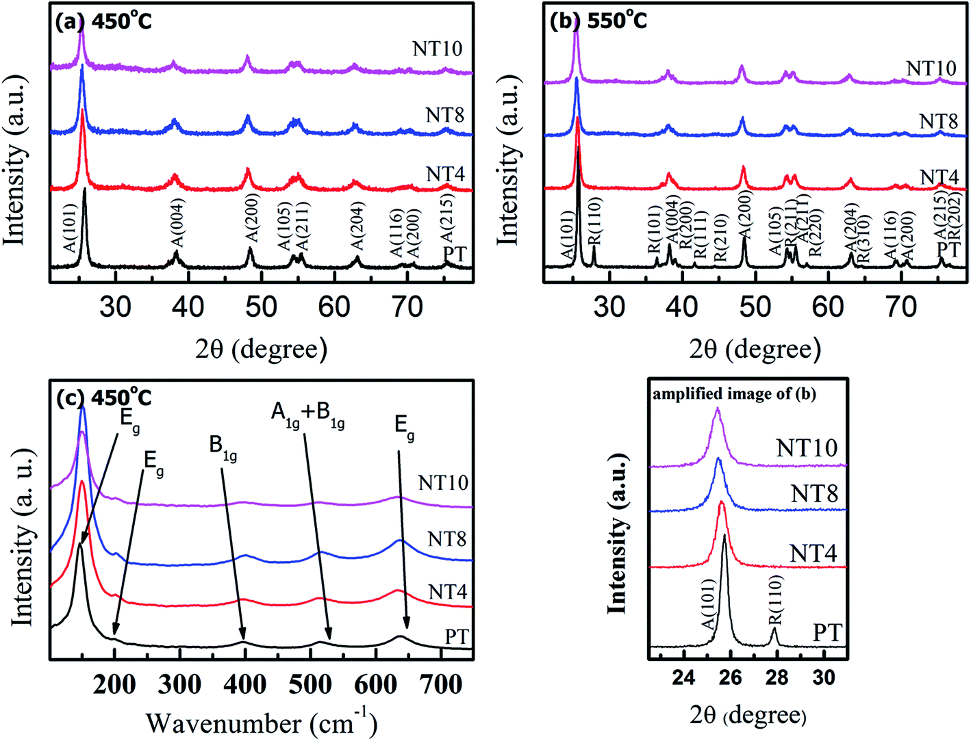 | ||
| Fig. 1 XRD patterns (a & b) and Raman spectra (c) of PT, NT4, NT8 and NT10. | ||
| Samples | 450 °C | 550 °C | ||
|---|---|---|---|---|
| 2θ (degree) A(101) | Crystallite sizea (nm) | 2θ (degree) A(101) | Crystallite sizea (nm) | |
| a The average crystallite size of nano-powder was determined by Debye Scherrer formula. | ||||
| PT | 25.722 | A(14.0 nm) | 25.729 | A(32.0 nm), R(35.5 nm) |
| NT4 | 25.466 | A(11.0 nm) | 25.626 | A(15.5 nm) |
| NT8 | 25.392 | A(10.5 nm) | 25.497 | A(13.0 nm) |
| NT10 | 25.328 | A(11.0 nm) | 25.436 | A(14.0 nm) |
The diffraction peak of crystal planes A(101) and R(110) were selected to calculate crystallite size of anatase and rutile phase respectively of all powders using Debye Scherrer formula. The estimated crystallite size of anatase and rutile TiO2 and 2θ values for A(101) planes are shown in Table 1. The results show that crystallite size decreases gradually upto 8 at% nominal Na doping and increases for NT10. Also, the crystallinity, as estimated from (101) peak intensity is enhanced with increase in Na doping upto 8 at% and thereafter decreases. In addition, samples calcined at 550 °C have large crystallite size due to enhanced agglomeration.
Besides, the crystallite size of powders in our work is found to be larger than that reported by H. Xie et al.14 This is attributed to the diethanolamine (DEA) stabilizer used by H. Xie et al.14 control the growth and agglomeration of nano-particles. In present work, no additional stabilizer is used, and solvent in itself plays role of stabilizing agent which makes it prone to agglomeration.18 However, doping of Na in TiO2 hinders the growth of crystallite size due to following reason. Substitution of large sized Na+ at Ti4+ and the consequent introduction of oxygen vacancies28 results in an increase in lattice parameter and strain, which results in decrease in crystallite size.22,29 The reason for increase in crystallinity with Na doping in TiO2 matrix is still unknown. However, XRD patterns reveal that stability of anatase phase is enhanced due to sodium doping, which might be responsible for the increased crystallinity.
Raman spectra (Fig. 1(c)) were recorded to further confirm crystallinity and phase components of pure and Na doped TiO2 nano-powder calcined at 450 °C. PT shows six characteristic Raman bands at 146 cm−1, 198 cm−1, 396 cm−1, 516 cm−1 and 638 cm−1, which corresponds to anatase phase.30 These Raman active bands are assigned to Eg, Eg, B1g, A1g + B1g and Eg respectively.30 Comparing the Raman spectra of pure TiO2 with Na doped TiO2; it is clear that all the Raman bands show blue shift in wavenumber. This is due to decrease in particle size with Na doping, resulting in an increase in surface to volume ratio, which is responsible for blue shift in wavenumber.31 Furthermore, intensity of Raman bands increases with Na doping, in agreement with the XRD result that crystallinity increases upto 8 at% Na doping.
BET surface area and pore distribution
Fig. 2 shows the N2 adsorption–desorption isotherms and pore size distribution of pure and Na doped TiO2 nano-powder calcined at 450 °C. It is clear from Fig. 2(a) that pure and Na doped TiO2 photo-catalyst exhibited isotherms of type IV, which is a typical characteristic of mesoporous materials.32 The shape of hysteresis loop is H2 type observed for ink-bottle shaped pores.33 With increase in Na doping, the change in position and shape of hysteresis loops are indication of variation in pore size and pore volume. The corresponding pore size distribution, calculated from desorption curve by the BJH method for pure and Na doped TiO2 is shown in Fig. 2(b). The obtained physical parameter such as BET surface area, pore volume and pore diameter are summarized in Table 2. The pore diameter and pore volume increases monotonically with Na doping, and reached maximum for NT8. Further doping reduces the pore size and pore volume, as could be seen for NT10. The growth in pore diameter with increasing Na doping is due to the increase in crystallinity of TiO2 nano-powder.33 It can be found that BET surface area, pore volume and pore diameter increased 50%, 97% and 15% respectively, as concentration of Na increased from 0 at% to 8 at% in TiO2 (Table 2).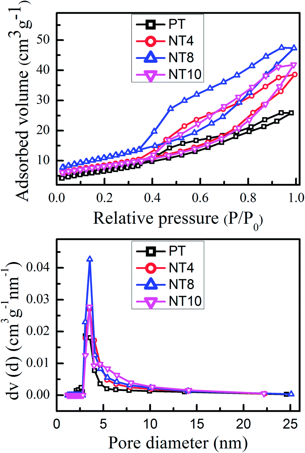 | ||
| Fig. 2 N2 adsorption–desorption isotherms (a) and pore diameter distribution curve (b) of PT, NT4, NT8 and NT10 calcined at 450 °C. | ||
| Nano-powder | Naa (at%) | Band gapb (eV) | pHpzcc | BET surface aread (m2 g−1) | Pore volumee (cc per g) | Pore diametere (nm) |
|---|---|---|---|---|---|---|
| a The actual Na concentration was determined by WDXRF spectroscopy.b Band gap was calculated using Tauc's relation.c The pHpzc was determined by measuring zeta potential of sample at different pH by zeta potential analyser.d The BET surface area was determined by multipoint BET method using adsorption data.e Pore volume and pore diameter were determined using desorption data by BJH method. | ||||||
| PT/450 | 0 | 3.37 | 5.7 | 26.274 | 0.044 | 3.086 |
| NT4/450 | 3.89 | 3.32 | 5.2 | 29.802 | 0.066 | 3.498 |
| NT8/450 | 7.81 | 3.30 | 4.9 | 39.584 | 0.087 | 3.548 |
| NT10/450 | 9.75 | 3.35 | 4.7 | 28.844 | 0.073 | 3.510 |
Morphological study
TEM and HRTEM were used for detailed analysis of morphology and structure of prepared pure and Na doped TiO2 nano-powder calcined at 450 °C. Bright field TEM images of PT (Fig. 3(a)) and NT8 (Fig. 3(b)) nano-powder clearly confirm that the representative particle size of NT8 nano-powder (7–10 nm) is smaller than PT nano-powder (15–20 nm). The SAED pattern (inset of Fig. 3(a and b)) confirm the crystalline phase of PT and NT8 nano-powders. The indexing of rings in SAED pattern corresponds to anatase phase of TiO2. HRTEM image reveal interplaner spacing corresponding to (101) planes to be 0.35 nm for PT nano-powder (Fig. 3(c)) and 0.36 nm for NT8 nano-powder (Fig. 3(d)). This increase in interplaner spacing could be attributed to the substitutional doping of large sized Na in TiO2 matrix, in agreement with XRD results.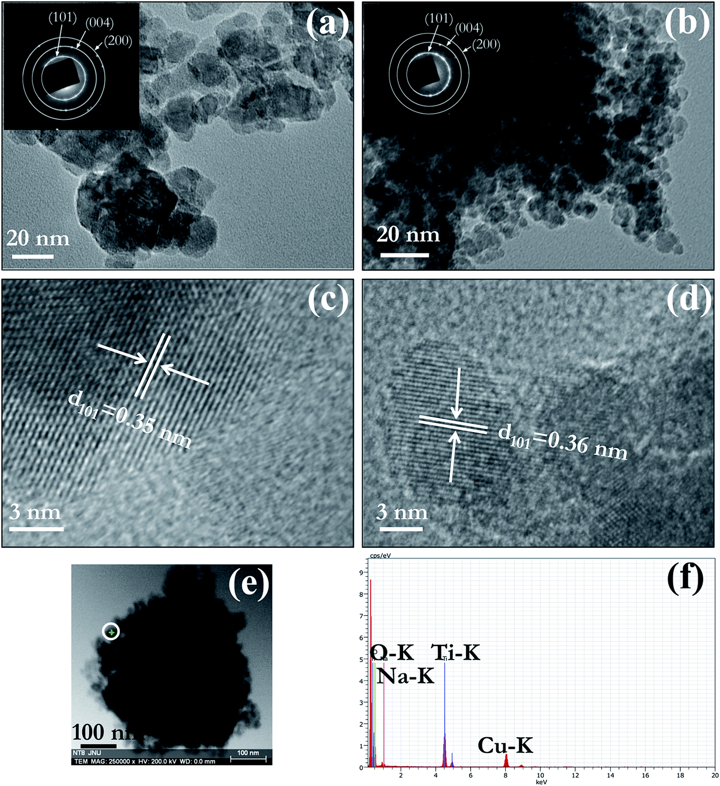 | ||
| Fig. 3 TEM bright field image of (a) PT/450 and (b) NT8/450 nano-powder. The SAED patterns of PT/450 and NT8/450 are as insets in (a & b) respectively. HRTEM images of (c) PT/450 and (d) NT8/450. (e) STEM bright field image of an agglomerate of NT8/450 nano-powder. (f) STEM-EDX point spectrum from a region marked by white circle in (e). | ||
STEM image of an agglomerate of NT8 nano-powder is shown in Fig. 3(e). A point EDX spectrum acquired from the region indicated by a white circle is shown in Fig. 3(f). Simultaneous presence of Na–K and Ti–K EDX peaks supports XRD and TEM results concerning Na doping of TiO2.
XPS analysis
XPS was employed for the surface composition and chemical states of prepared nano-powder samples calcined at 450 °C. The obtained high resolution XPS spectra of O 1s, Ti 2p and Na 1s are shown in Fig. 4 and fitted using Voigt function. The high resolution XPS scan of O 1s of PT sample (Fig. 4(a)) can be fitted into two peaks including Ti–O link (529.9 eV) and O–H link (532.0 eV, due to adsorbed surface hydroxy group).34,35 The peak corresponding to O–H link for O 1s of NT8 sample (Fig. 4(b)) shows an increase in intensity. This is obvious due to large surface area of NT8 nano-powder (confirmed by BET surface area measurements) favorable for more adsorption of hydroxyl groups.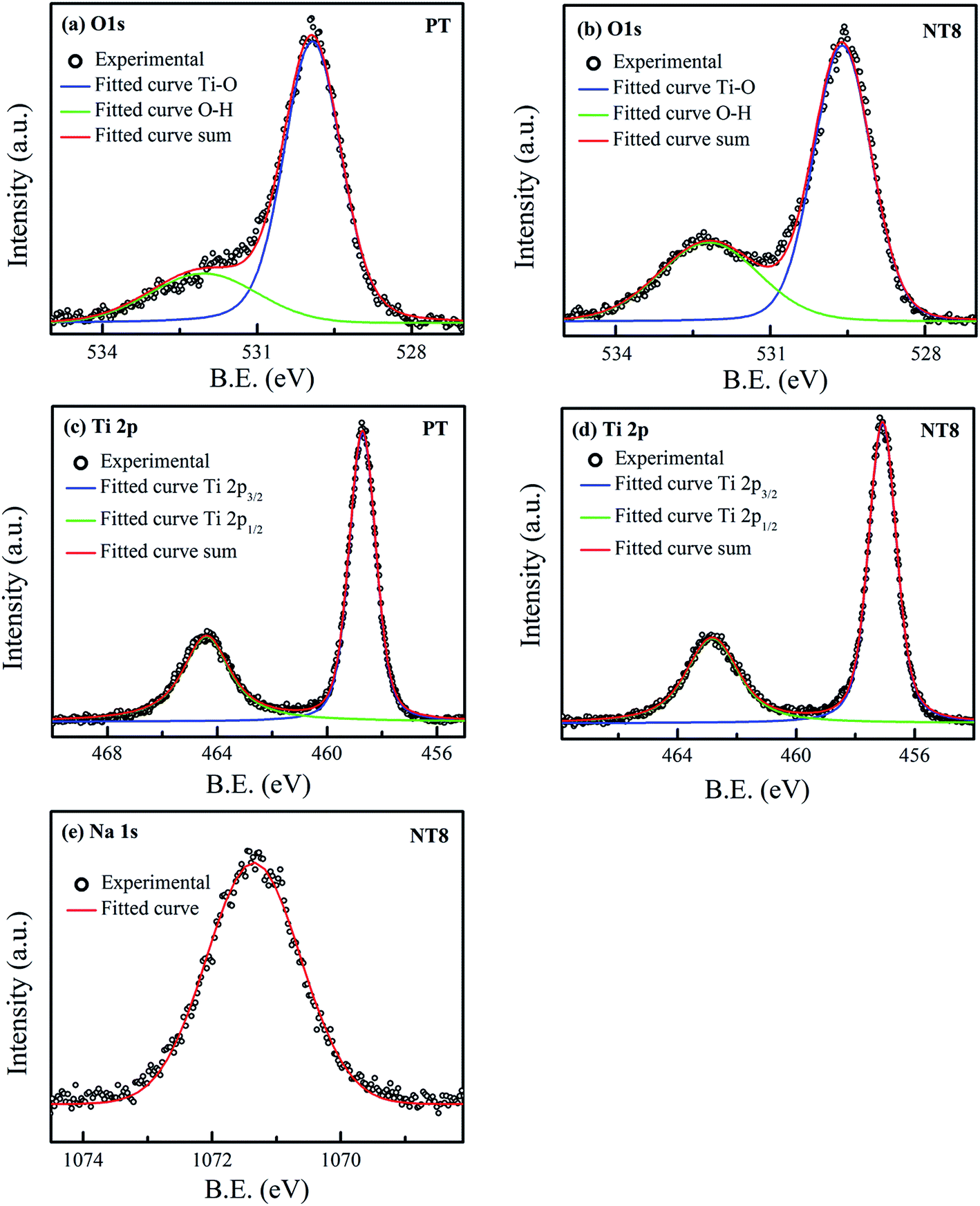 | ||
| Fig. 4 High resolution XPS spectra of (a) O 1s and (c) Ti 2p, of PT/450; (b) O 1s, (d) Ti 2p and (e) Na 1s, of NT8/450. | ||
Fig. 4(c and d) provides the high resolution XPS scan of Ti 2p of PT and NT8 samples respectively. The double peaks of Ti 2p after deconvolution corresponds to Ti 2p1/2 and Ti 2p3/2. The peaks Ti 2p1/2 (464.4 eV) and Ti 2p3/2 (458.7 eV) of PT sample represent the core level binding energy of Ti4+ oxidation state.35 In NT8 sample both peaks of Ti 2p shift to lower binding energy. Similar results are observed for the binding energy of O 1s (Ti–O link) of NT8 sample. This is attributed to the lower electronegativity of Na (0.93) than that of Ti (1.52), which confirms the substitutional doping of Na1+ at Ti4+ site.36 The Na1+ oxidation state is confirmed by high resolution XPS scan of Na 1s (Fig. 4(e)) with core level binding energy at 1071.3 eV.37
Optical properties
The band gap of pure and Na doped TiO2 nano-powder calcined at 450 °C was determined using Tauc's relation for direct band gap semiconductor38 as:| αhυ = B(hυ − Eg)1/2 | (4) |
Fig. 5(a) and its inset showed UV-Visible absorbance spectra and Tauc's plot for pure and Na doped TiO2 nano-powder respectively. It is clear from Tauc's plot that there is no possibility of absorption in visible range and therefore photocatalytic activity is inhibited under visible light irradiation, as also reported by G. Yang et al.12 The band gap decreases upto optimal Na doping and the experimentally measured band gaps for all samples are shown in Table 2.
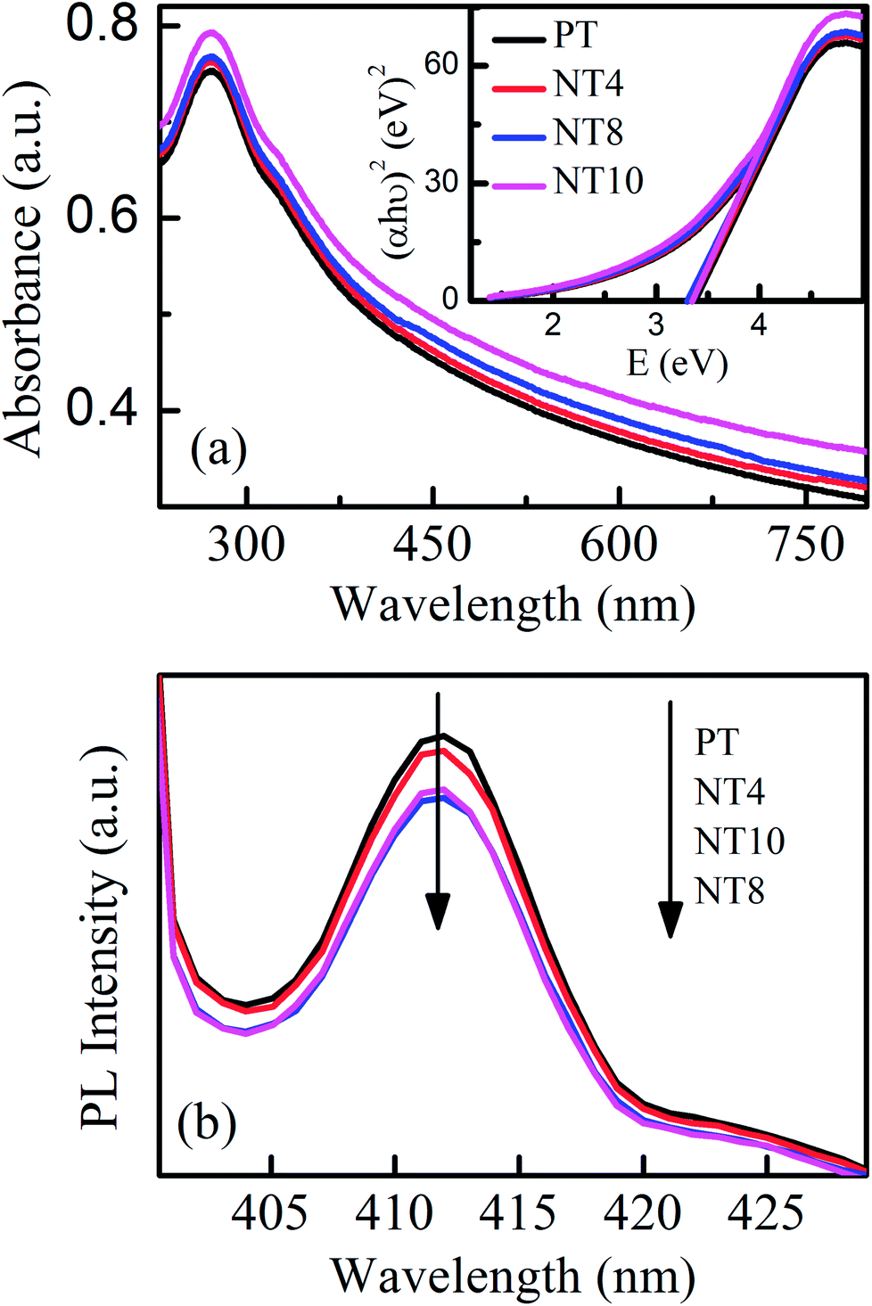 | ||
| Fig. 5 UV-Visible absorption spectra (a) and PL spectra (b) of PT, NT4, NT8 and NT10 calcined at 450 °C. The inset of (a) shows corresponding Tauc's plot. | ||
Fig. 5(b) shows the PL spectra of pure and Na doped TiO2 nano-powder calcined at 450 °C with excitation wavelength 390 nm (matching with band edge of TiO2). The PL emission band at 412 nm (3.0 eV) is attributed to shallow-traps39 and related to electron hole recombination rate. The shape of PL signal remains same for pure and Na doped TiO2 nano-powder but intensity reduces upto NT8 sample and thereafter increases. This is attributed to creation of oxygen vacancies with Na doping, which trap the electrons from conduction band and therefore reduce electron hole recombination rate. However, excessive formation of oxygen vacancies act as recombination centres40 and enhance the PL signal intensity. Thus rate of electron–hole recombination reduces with optimal Na doping and will certainly enhance photocatalytic activity.
Determination of pHpzc
The pHpzc of nano-powder represents the value of pH at which zeta potential or equivalently the net charge on the surface of nano-powder is zero. When pH of solution is greater than pHpzc, nano-powder surface is negatively charged resulting in adsorption of cations at the surface.41 The pHpzc values of pure and Na doped TiO2 nano-powder calcined at 450 °C are listed in Table 2. It reveals that pHpzc value reduces with Na doping. This could be attributed to the increased adsorption of hydroxyl groups (confirmed by XPS).Photocatalytic activity
The photocatalytic activity of pure and Na doped TiO2 photo-catalyst is evaluated by degrading MB dye under UV irradiation. The plots of degradation percentage with and without photo-catalyst under 60 minute of UV irradiation are shown in Fig. 6(a and b). For comparison, the photocatalytic performance of well-known commercially available P25 TiO2 photo-catalyst is also evaluated under similar environment. The degradation percentage value for MB is nearly 5% only, when experiment was performed without catalyst (WC), which is negligible. PT/450 photo-catalyst also shows much lower photocatalytic activity as compared to P25. However, doping of Na in TiO2 changes the scenario and NT8/450 photo-catalyst results in activity better than commercial P25 photo-catalyst. At calcination temperature 550 °C, PT shows higher photocatalytic activity then PT/450 but, NT4, NT8 and NT10 photo-catalyst shows activity lower than commercially available P25. The k values for all photo-catalyst are tabulated in Table 3. The k value of NT8/450 photo-catalyst is highest and reaches to 4.32 × 10⁻² min−1 for MB dye degradation. The results obtained from degree of mineralization of organic dye (Fig. 6(c and d)) are in accordance with photocatalytic degradation results.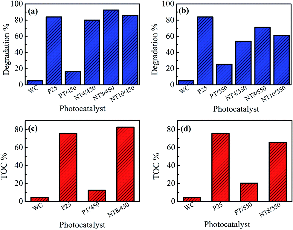 | ||
| Fig. 6 Photo-catalytic degradation (a & b) and mineralization (c & d) of MB dye under 60 minute of UV irradiation. | ||
| Catalyst | WC | P25 | PT/450 | NT4/450 | NT8/450 | NT10/450 | PT/550 | NT4/550 | NT8/550 | NT10/550 |
|---|---|---|---|---|---|---|---|---|---|---|
| k (×10−3 min−1) | 0.86 | 30.52 | 3.02 | 26.81 | 43.24 | 32.79 | 4.89 | 12.92 | 20.67 | 15.85 |
The enhancement in degradation rate of dye by NT8/450 sample can be ascribed to high surface area, crystallinity and reduced rate of electron–hole recombination as compared to other samples. In addition, the degradation experiments are performed at pH 5, which is greater than pHpzc of NT8/450. This leads to strong adsorption of cationic MB dye at surface of NT8/450 nano-powder. It is well known that photocatalytic activity of photo-catalyst is influenced by surface area, which affect the adsorption and diffusion of reactants.33,42,43 In addition, optimal Na doping results in oxygen vacancies that entrap electrons and reduces electron–hole recombination rate (as confirmed by PL spectra) and results in increased photocatalytic activity. This is also confirmed by the fact that NT10/450 photo-catalyst shows better photo-catalytic activity as compared to NT4/450. The surface area of NT10/450 sample is comparable to NT4/450 sample but the reduced rate of electron–hole recombination appears to be mainly responsible for higher photocatalytic activity of NT10/450 photo-catalyst. Therefore, high surface area alone is not responsible factor for higher photocatalytic activity. It is the combination of reduced electron–hole recombination rate, high surface area and crystallinity that decides the photocatalytic activity. At higher calcination temperature, the crystallite size increases, which results in decrease in surface area and hence declined photocatalytic activity. The mechanism of photocatalytic degradation of MB dye at surface of PT and NT8 is illustrated in Fig. 7.
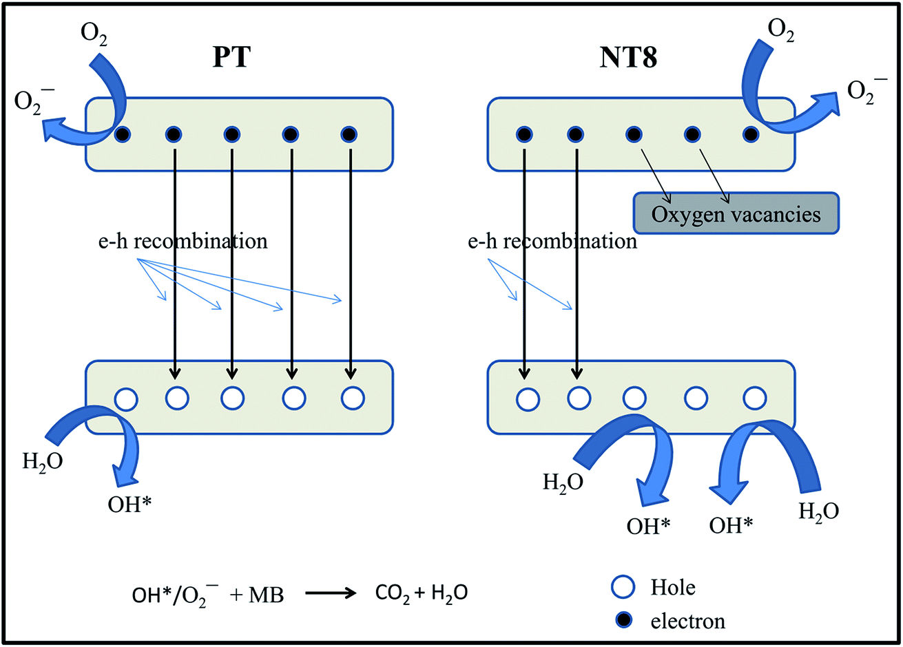 | ||
| Fig. 7 Mechanism of photocatalytic degradation of dye by pure and Na doped TiO2 nano-powder. | ||
It is important to calculate degradation percentage during recycling of photo-catalyst. Therefore, degradation percentage of MB dye by NT8/450 photo-catalyst for six cycles is shown in Fig. 8(a). After four cycles, degradation percentage drops only marginally from 92.5% to 76.1% which implies prepared photo-catalyst is quite stable for repeated use and thereafter it reduces drastically for 5th and 6th cycle.
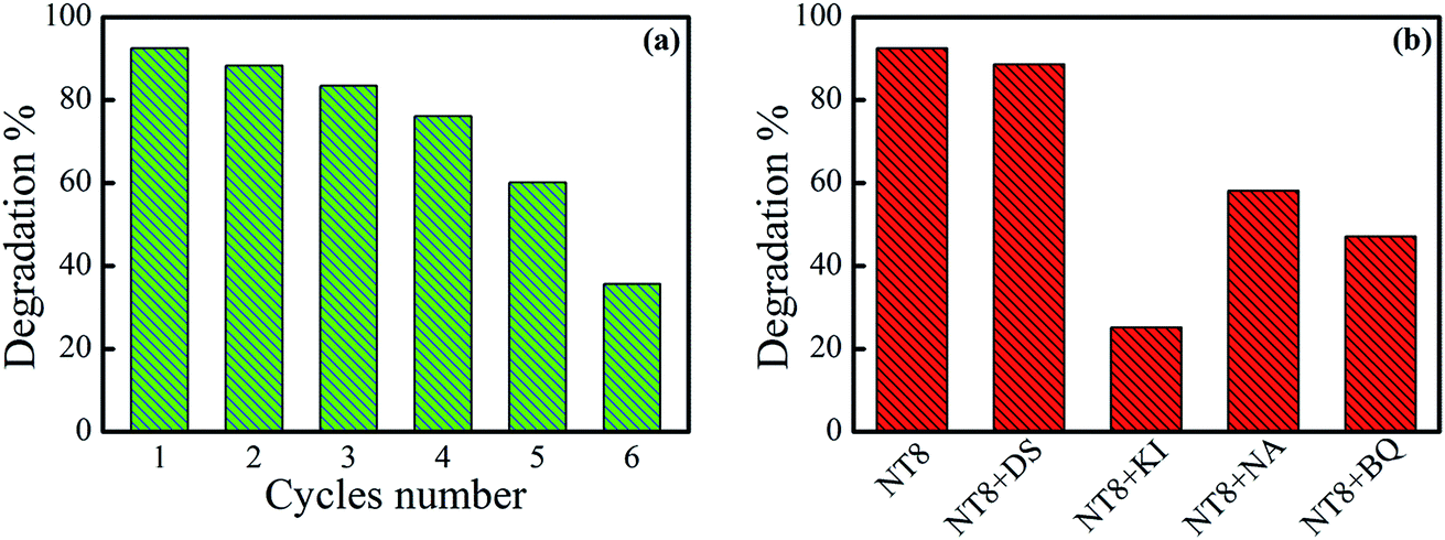 | ||
| Fig. 8 (a) Recycling experiment for NT8/450 photo-catalyst for degradation of 5 ppm MB dye under UV irradiation and irradiation time of 60 min. (b) Effect of various quenchers on percentage degradation of MB by NT8/450. | ||
In addition, the degradation percentage plot measured for degradation of MB in the presence of 1 mM concentration of different quenchers along with NT8/450 photo-catalyst is shown in Fig. 8(b). In presence of DS quencher there is very small reduction in degradation percentage and indicates negligible contribution of *OH radical in photo-catalytic degradation of dye. The degradation percentage reduces from 92.5 to 25.1 in presence of KI quencher. This indicates the dominant contribution of h+ species for degradation of MB dye in the presence of NT8/450 photo-catalyst. Degradation measurement in the presence of NA and BQ quenchers revealed moderate contribution of 1O2 and O2− respectively.
Conclusion
Mesoporous Na doped TiO2 nano-powder is successfully prepared by solvent controlled non aqueous sol–gel route. Effect of Na doping on the crystallinity, size, morphology, surface area, porosity and photocatalytic activity of TiO2 have been studied in detail. XRD, TEM and XPS results confirm the substitutional doping Na at Ti site. Nominal 8 at% Na doping in TiO2 at calcination temperature 450 °C shows reduced electron–hole recombination rate, highest surface area and maximum crystallinity. Therefore, NT8/450 shows best photo-catalytic activity among all prepared samples. The combined effect of electron–hole recombination rate, surface area and crystallinity is responsible for its higher photo-catalytic activity.Conflicts of interest
There are no conflicts of interest to declare.Acknowledgements
We kindly acknowledge advanced instrumentation research facility (AIRF), JNU, New Delhi for access to WDXRF, FESEM and TEM instruments (DBT grant number BT/PR3130/INF/22/139/2011). We also acknowledge SPS, JNU New Delhi, BIT, Bangalore, GJUS&T, Hisar and MNIT Jaipur for access to XRD, BET, TOC and XPS facility respectively. I. Singh is thankful to university grant commission (UGC), India for providing SRF fellowship. B. B acknowledges financial support via UPE-II (project ID 102), DST Purse-II grant and Jawaharlal Nehru University, New Delhi.References
- M. Guerrero, A. Altube, L. E. Garcia, E. Rossinyol, M. D. Baro, E. Pellicer and J. Sort, ACS Appl. Mater. Interfaces, 2014, 6, 13994–14000 CAS.
- R. Daghrir, P. Drogui and D. Robert, Ind. Eng. Chem. Res., 2013, 52, 3581–3599 CrossRef CAS.
- M. Kapilashrami, Y. Zhang, Y.-S. Liu, A. Hagfeldt and J. Guo, Chem. Rev., 2014, 114, 9662–9707 CrossRef CAS PubMed.
- M. Ni, M. K. H. H. Leung, D. Y. C. C. Leung and K. Sumathy, Renewable Sustainable Energy Rev., 2007, 11, 401–425 CrossRef CAS.
- Y.-H. Tseng, C.-S. Kuo, C.-H. Huang, Y.-Y. Li, P.-W. Chou, C.-L. Cheng and M.-S. Wong, Nanotechnology, 2006, 17, 2490–2497 CrossRef CAS PubMed.
- D. Reyes-Coronado, G. Rodríguez-Gattorno, M. E. Espinosa-Pesqueira, C. Cab, R. de Coss and G. Oskam, Nanotechnology, 2008, 19, 145605 CrossRef CAS PubMed.
- A. Zaleska, Recent Pat. Eng., 2008, 2, 157–164 CrossRef CAS.
- S. M. Gupta and M. Tripathi, Chin. Sci. Bull., 2011, 56, 1639–1657 CrossRef CAS.
- T. López, J. Hernandez-Ventura, R. Gómez, F. Tzompantzi, E. Sánchez, X. Bokhimi and A. García, J. Mol. Catal. A: Chem., 2001, 167, 101–107 CrossRef.
- Y. Bessekhouad, D. Robert, J. V. Weber and N. Chaoui, J. Photochem. Photobiol., A, 2004, 167, 49–57 CrossRef CAS.
- L. C. Chen, C. M. Huang and F. R. Tsai, J. Mol. Catal. A: Chem., 2007, 265, 133–140 CrossRef CAS.
- G. Yang, Z. Yan, T. Xiao and B. Yang, J. Alloys Compd., 2013, 580, 15–22 CrossRef CAS.
- P. Panagiotopoulou and D. I. Kondarides, J. Catal., 2009, 267, 57–66 CrossRef CAS.
- H. Xie, N. Li, B. Liu, J. Yang and X. Zhao, J. Phys. Chem. C, 2016, 120, 10390–10399 CAS.
- G. Garnweitner and M. Niederberger, J. Am. Ceram. Soc., 2006, 89, 1801–1808 CrossRef CAS.
- M. Niederberger, G. Garnweitner, N. Pinna and G. Neri, Prog. Solid State Chem., 2005, 33, 59–70 CrossRef CAS.
- M. Niederberger, Acc. Chem. Res., 2007, 40, 793–800 CrossRef CAS PubMed.
- N. Pinna and M. Niederberger, Angew. Chem., Int. Ed., 2008, 47, 5292–5304 CrossRef CAS PubMed.
- Q. Yuan, R. Ravikrishna and K. T. Valsaraj, Sep. Purif. Technol., 2001, 24, 309–318 CrossRef CAS.
- E. Ukaji, T. Furusawa, M. Sato and N. Suzuki, Appl. Surf. Sci., 2007, 254, 563–569 CrossRef CAS.
- M. Niederberger, G. Garnweitner, J. Ba, J. Polleux and N. Pinna, Int. J. Nanotechnol., 2007, 4, 263–281 CrossRef CAS.
- I. Singh, R. Kumar and B. I. Birajdar, J. Environ. Chem. Eng., 2017, 5, 2955–2963 CrossRef CAS.
- L. Kuang, Y. Zhao, W. Zhang and S. Ge, J. Environ. Eng., 2016, 4015065 CrossRef.
- A. Pochon, P. P. Vaughan, D. Gan, P. Vath, N. V. Blough and D. E. Falvey, J. Phys. Chem. A, 2002, 106, 2889–2894 CrossRef CAS.
- S. T. Martin, A. T. Lee and M. R. Hoffmann, Environ. Sci. Technol., 1995, 29, 2567–2573 CrossRef CAS PubMed.
- J. Rabani, K. Yamashita, K. Ushida, J. Stark and A. Kira, J. Phys. Chem. B, 1998, 102, 1689–1695 CrossRef CAS.
- Y. Cao, W. Yang, W. Zhang, G. Liu, P. Yue, C. W. Bay and H. Kong, New J. Chem., 2004, 28, 218–222 RSC.
- X. Pan, M.-Q. Yang, X. Fu, N. Zhang and Y.-J. Xu, Nanoscale, 2013, 5, 3601 RSC.
- S. Deshpande, S. Patil, S. V. Kuchibhatla and S. Seal, Appl. Phys. Lett., 2005, 87, 1–3 CrossRef.
- W. F. Zhang, Y. L. He, M. S. Zhang, Z. Yin and Q. Chen, J. Phys. D: Appl. Phys., 2000, 33, 912–916 CrossRef CAS.
- H. C. Choi, Y. M. Jung and S. Bin Kim, Vib. Spectrosc., 2005, 37, 33–38 CrossRef CAS.
- F. Guo, H. Li, Z. Zhang, S. Meng and D. Li, Mater. Sci. Eng., B, 2009, 163, 134–137 CrossRef CAS.
- J. Yu, G. Wang, B. Cheng and M. Zhou, Appl. Catal., B, 2007, 69, 171–180 CrossRef CAS.
- G. W. Simmons and B. C. Beard, J. Phys. Chem., 1987, 91, 1143–1148 CrossRef CAS.
- C. Su, L. Liu, M. Zhang, Y. Zhang and C. Shao, CrystEngComm, 2012, 14, 3989 RSC.
- J. Wang, Y. Yu, S. Li, L. Guo, E. Wang and Y. Cao, J. Phys. Chem. C, 2013, 117, 27120–27126 CAS.
- Z. Guo, J. Zhou, L. An, J. Jiang, G. Zhu and C. Deng, J. Mater. Chem. A, 2014, 2, 20358–20366 CAS.
- N. Serpone, D. Lawless and R. Khairutdinov, J. Phys. Chem., 1995, 99, 16646–16654 CrossRef CAS.
- N. Daude, C. Gout and C. Jouanin, Phys. Rev. B, 1977, 15, 3229–3235 CrossRef CAS.
- M. Bellardita, M. Addamo, A. Di Paola and L. Palmisano, Chem. Phys., 2007, 339, 94–103 CrossRef CAS.
- A. Eslami, M. M. Amini, A. R. Yazdanbakhsh, A. Safari and A. Asadi, J. Chem. Technol. Biotechnol., 2016, 91, 2693–2704 CrossRef CAS.
- M. Xue, L. Huang, J.-Q. Wang, Y. Wang, L. Gao, J.-H. Zhu and Z.-G. Zou, Nanotechnology, 2008, 19, 185604 CrossRef PubMed.
- D. Liu, Y. Lv, M. Zhang, Y. Liu, Y. Zhu, R. Zong and Y. Zhu, J. Mater. Chem. A, 2014, 2, 15377–15388 CAS.
| This journal is © The Royal Society of Chemistry 2017 |