 Open Access Article
Flexible grid-mesh electrodes fabricated by electroless copper plating on corona-treated PET substrates and coating with graphene for transparent film heaters†
Bu-Jong Kim,
Jong-Seol Park,
Ria Yoo and
Jin-Seok Park *
*
Department of Electronic Systems Engineering, Hanyang University at ERICA Campus, 1271, Sa 3-dong, Sangnok-gu, Ansan, Gyeonggi-do 426-791, Republic of Korea. E-mail: jinsp@hanyang.ac.kr
First published on 16th November 2017
Abstract
In this study, we present solution-based processes for producing copper (Cu) meshes which can be utilized as transparent conductive electrodes (TCEs) for flexible film heaters. The surface modification of polyethylene terephthalate (PET) substrates was done via corona treatment at atmospheric pressure and room temperature. The Cu layer was deposited on the corona-treated PET substrate via electroless plating and then patterned via lithography to have mesh dimensions of a 200 μm line-to-line spacing and a 6 μm line width. Also, graphene was coated on the Cu mesh via electrophoretic deposition (EPD). The chemical and physical changes in the PET surfaces were characterized according to the corona treatment conditions. The measurements of contact angles and surface energies of the corona-treated PET substrates indicated that the PET surfaces changed from hydrophobic to hydrophilic after corona treatment, leading to the improvement in the adhesion between the PET substrates and the Cu meshes. The flexibility of the Cu meshes was inspected by performing bending and twisting tests and by directly measuring the adhesion strength between the Cu layers and the PET substrates through scratch tests. The effects of graphene coating on the characteristics of the Cu meshes were examined in terms of their surface morphologies, electrical sheet resistances, transmittances and reflectances in the visible-light wavelength range, and color differences. Finally, the film heaters produced by employing the graphene-coated Cu meshes yielded a temperature rise over 85 °C with a response time shorter than 20 s.
Introduction
Transparent conductive electrodes (TCEs) have been utilized for a variety of applications, including touch screen panels,1,2 solar cells,3,4 film heaters,5,6 and displays.7,8 Up to now, thin films of indium-tin-oxide (ITO) as TCEs have been the most widely used. However, ITO is not compatible with the flexible versions of these devices due to its brittle nature as well as a high processing temperature.9 This has recently motivated research for finding alternative materials for ITO films, such as carbon nanotubes (CNTs),10,11 graphene,12,13 conductive polymers,14,15 metal nanowires,16,17 and metal meshes.18,19Among the aforementioned materials, metal meshes have potential for commercialization due to their low electric sheet resistance and high visible transmittance. However, metal meshes inherently have a relatively high reflectance generated by the metals. Furthermore, several metals, such as gold (Au) and copper (Cu), are generally tinged specific colors, leading to a visibility problem. In order to solve the poor visibility problems, metals need to be coated with a black material capable of absorbing light effectively. Graphene is known as an excellent absorber of visible light and has advantages in terms of chemical stability, thermal and electric conductivity, mechanical strength, and flexibility.20
Meanwhile, most of the currently-developed metal meshes have been fabricated by sputtering, which incurs high manufacturing costs due to vacuum and complicated processes. Recently, a variety of solution processes are adopted to produce metal meshes as they are simple and relatively inexpensive.21 However, the solution processes have common problems regarding the weak adhesion between the flexible substrates and the coating materials.22 Generally, plasma treatment has been widely used as the surface modification method to improve the adhesion between the flexible substrates and the coating layers formed on them.23 This method includes the chemical modification by which polar groups can be formed on the surface of substrate before film deposition, and also offers the physical change which can increase the area of surface via the formation of nano-scratches. The plasma treatment, however, forcibly demands several processing requirements such as low working pressures, long treatment times, and high process temperatures.
In this study, we present solution-based processes for fabricating Cu meshes on the polyethylene terephthalate (PET) substrates, which can be employed as the TCEs for flexible film heaters. Prior to the deposition of the Cu layer, the surface modification of the PET substrates was done via corona treatment at atmospheric pressure and room temperature. The Cu layers were deposited on the corona-treated PET substrates via electroless plating and then coated with graphene via electrophoretic deposition (EPD). The chemical and physical changes in the PET surfaces were characterized according to the corona treatment conditions such as the number of treatments, the treatment times, and the applied corona energy density. The flexibility of the Cu meshes was inspected by performing bending and twisting tests, and by directly measuring the adhesion strength between the Cu layers and the PET substrates through scratch tests. The effects of graphene coating on the characteristics of the Cu meshes were examined in terms of their surface morphologies, electrical sheet resistances, transmittances and reflectances in the visible-light wavelength range, and color differences. Finally, the thermal characteristics of film heaters produced in this study by employing the graphene-coated Cu meshes were measured using an infrared ray camera.
Results and discussion
Surface modification of PET substrates via corona treatment
The surface images of liquid drops that varied with the contact angles (θc) of the PET substrates are compared in Fig. 1(a)–(f), according to the numbers of corona-treatment. Two kinds of liquids such as water and diiodomethane were used in the θc measurement.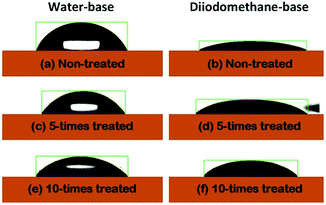 | ||
| Fig. 1 The surface images of the liquid drops, such as water and diiodomethane, on the surfaces of the PET substrates as a function of the repetition numbers of the corona treatment. | ||
The estimated θc values are displayed Fig. 2(a). The θc values based on water were seen to have monotonically decreased by increasing the number of corona-treatment. The opposite situation was discovered in the case of the θc values measured with the diiodomethane-base liquid. From the θc values, the surface energies of the PET substrates were also calculated using the formula in the Owens–Wendt's model.24 Fig. 2(b) shows the polar components (EP) calculated from the water-based θc values, the dispersive components (ED) calculated from the diiodomethane-based θc values, and the total surface energy (ES) obtained from the sum of EP and ED. The ES values were observed to have increased as the numbers of the corona treatment increased. This indicated that the chemical characteristic of the PET's surface was increasingly changing to a hydrophilic nature by increasing the numbers of corona-treatment. This was because molecular bonds on the surface of the PET substrate are broken during the corona treatment and the broken bonds are then recombined with free radicals in the corona environment to form polar groups on the PET's surface.25 The related chemical analysis on this issue was reported in our previous study.26
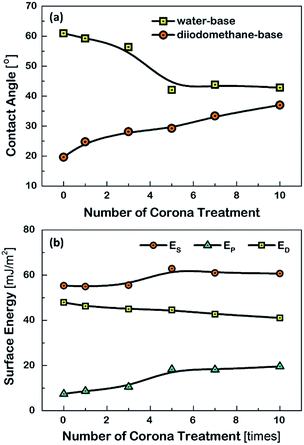 | ||
| Fig. 2 (a) The estimated contact angles and (b) the surface energy of the PET substrates, as a function of the repetition numbers of the corona treatment. | ||
It was also observed that the Cu films, when they were deposited on the non-treated PET or the once corona-treated PET substrate via electroless plating, were partially peeled off from the PET substrates as shown in Fig. S1(a) and (b).† On the other hand, the Cu films, when they were deposited on the corona-treated PET substrates more than 5 times, were well plated on the PET substrates without being peeled off, as shown in Fig. S1(c) and (d).† This was because the adhesive force between the PET substrates and the Cu films was increased by increasing the numbers of corona treatment, as had already been discussed with the surface energy.
In addition, the uniformities of the Cu films, which were deposited via electroless plating using the water-based solution, were examined by measuring the electric sheet resistances at the different measurement positions, as shown in the inset of Fig. S2(a).† The uniformity is described as the deviation of the sheet resistance measured at each position with respect to the average sheet resistance value (i.e., ΔR/Rave, %).
The results indicated that the uniformity was better for the Cu film deposited on the 10-times corona-treated PET substrate than that deposited on the 3-times corona-treated PET substrate. This may be related to the wettability of the PET substrate.27 The result of Fig. S2(a)† indicated that the wettability of the PET substrate was improved by increasing the numbers of the corona treatment. The wetting energy of the PET substrate was also calculated from the water-based θc value, as displayed in Fig. S2(b).† Increasing the numbers of corona treatment led to the increase in the wetting energy, indicating that the adhesion strength increased.28
Characteristics of Cu meshes fabricated on corona-treated PETs
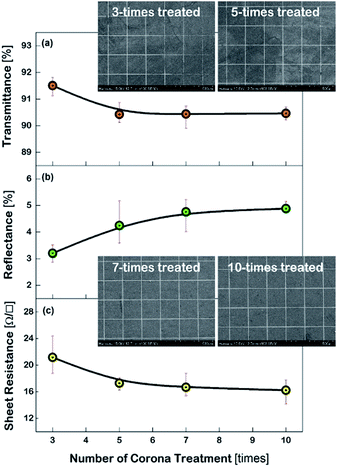
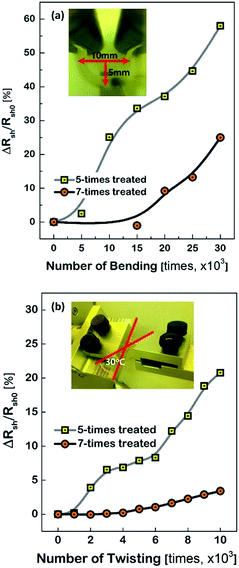
Fig. 3 shows the characteristics of the Cu meshes fabricated on the corona-treated PET substrates, such as the transmittance (T550) and reflectance (R550) measured in the wavelength of 550 nm, and the sheet resistance (Rsh), as a function of the repetition numbers of the corona treatment. By increasing the treatment numbers from 3 times to 10 times, the T550 slightly decreased from 91.5% to 90.4% and the R550 increased from 3.2% to 4.8%, and the Rsh decreased from 21.2 Ω □−1 to 16.2 Ω □−1. This may result from the difference in the areas where the Cu meshes were formed. As can be seen from the FESEM images of the Cu meshes shown in Fig. 3, for the Cu mesh deposited on the 3-times corona-treated PET substrate, the mesh patterns were partially broken or missing due to the relatively weak adhesion. For the Cu meshes deposited on the 7-times or 10-times corona-treated PET substrates, on the other hand, unimpaired mesh patterns without broken or missing patterns were observed.The effect of corona-treatment on the flexibility of the Cu meshes deposited on PET substrates was also examined. The flexibility was quantitatively measured by recording the changes in the Rsh of the Cu meshes due to the application of repetitive bending and twisting. As can be seen from the photos shown in the insets of Fig. 4(a) and (b), the bending test was performed with the bending radius of 5 mm and the twisting test was carried out with the twisting angle of 30°.
As the numbers of bending and twisting increased, the Rsh values of the Cu meshes gradually increased. It should be noted, however, that the rise of the Rsh due to the bending or twist test was observed to have been substantially mitigated by increasing the numbers of corona treatment. For instance, the changes in the sheet resistance after 30![[thin space (1/6-em)]](https://www.rsc.org/images/entities/char_2009.gif) 000 times of bending with respect to the initial sheet resistance (i.e., ΔRsh/Rsh0) were measured to be approximately 58.0% for the Cu mesh fabricated on the 5-times corona-treated PET substrate and 25.0% for the Cu mesh fabricated on the 7-times corona-treated PET substrate. Also, the ΔRsh/Rsh0 values after 10
000 times of bending with respect to the initial sheet resistance (i.e., ΔRsh/Rsh0) were measured to be approximately 58.0% for the Cu mesh fabricated on the 5-times corona-treated PET substrate and 25.0% for the Cu mesh fabricated on the 7-times corona-treated PET substrate. Also, the ΔRsh/Rsh0 values after 10![[thin space (1/6-em)]](https://www.rsc.org/images/entities/char_2009.gif) 000 times of twisting were measured to be approximately 20.8% for the case of the 5-times corona-treated PET substrate and only 3.4% for the case of the 7-times corona-treated PET substrate.
000 times of twisting were measured to be approximately 20.8% for the case of the 5-times corona-treated PET substrate and only 3.4% for the case of the 7-times corona-treated PET substrate.
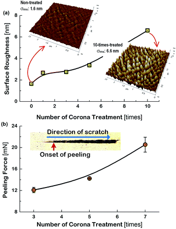
Generally, the electrode layers can be delaminated from the substrate due to the compressive force during the bending and twist test. Accordingly, the result that the Cu meshes fabricated on the more corona-treated PET substrates yielded the smaller increment of the Rsh after the flexibility tests was attributed to the strengthened adhesion between the Cu mesh and the PET substrate. To examine how the physical change of the PET substrate due to corona treatment affected the flexibility of the Cu mesh, the change in the surface roughness of the PET substrate was measured. The root-mean-square surface roughness (σrms) values of the PET substrates were measured by increasing the numbers of corona treatment and the result is shown in Fig. 5(a), along with the AFM images of the non-treated and 10-times treated PET substrates. The non-treated PET substrate showed a relatively smooth surface with approximately 1.6 nm of σrms. In contrast, for the 10-times corona-treated PET substrate, the σrms was significantly increased to about 6.6 nm. This resulted from the generation of nano-scratches during corona treatment. Also, this indicated that the rough surface of the PET substrate resulted in the increase of surface energy and also served as the anchor leading to higher adhesive strength between the Cu mesh and the PET substrate.
In addition, a scratch test was performed for the Cu sheets deposited on the corona-treated PET substrates by increasing the applied force to the specimens from 0.3 mN to 50 mN. The results for the specimens that used the 3-times, 5-times, and 7-times corona-treated PET substrates are displayed in Fig. 5(b).
The picture in the inset of Fig. 5(b) indicates the onset of peeling (i.e., peeling force) of the Cu sheet and the scratching direction. The peeling force increased from 12.1 mN for the 3-times treated specimen to 20.5 mN for the 7-times treated specimen, indicating the increase of the adhesive force between the PET substrate and the Cu sheet. This may be the mechanical evidence responsible for the observations of Fig. 4 that the flexibility of the Cu mesh could be improved by corona treatment of the PET substrate.
Effects of graphene coating on Cu mesh
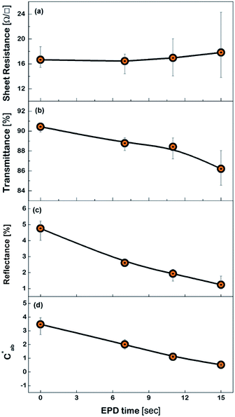
Fig. 6 shows the FESEM photo of the Cu mesh coated with grapheme via electrophoretic deposition (EPD), along with the enlarged photo of the surface morphology of the graphene coating layer. It is clearly seen that graphene was selectively coated only on the surfaces where the Cu mesh patterns had been formed. The results of Fig. 7 show the changes in the Rsh, T550, R550, and color difference of the Cu meshes as a function of the EPD time used for the coating of graphene. Here, all of the graphene-coated Cu meshes were fabricated using the 7-times corona-treated PET substrates.
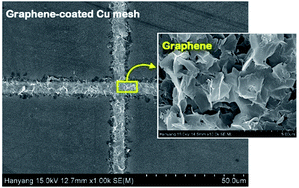 | ||
| Fig. 6 The FESEM image of the graphene-coated Cu meshes, along with the surface morphology of the graphene layer. | ||
The Rsh was hardly affected regardless of graphene coating as shown in Fig. 7(a). The T550 was slightly decreased by increasing the EPD time, but it still maintained higher than 85%, as shown in Fig. 7(b). Meanwhile, the R550 was significantly reduced by graphene coating as shown in Fig. 7(c). For instance, the R550 was about 4.7% for the Cu mesh without graphene coating and decreased to about 1.9% for the Cu mesh coated with graphene via 11 s of EPD. This indicated that the graphene coating layer played the role of suppressing the visible light reflected from the Cu mesh.
Generally, the color property of a metal mesh is closely related to its reflectance spectrum, from which the chromatic parameters, such as redness (a*) and yellowness (b*), can be determined. The value of parameter a* is the positive definiteness (+) that comes close to the color red as it increases, and close to the color green as it increases with negative definiteness (−). The value of parameter b* comes close to the color yellow as it increases with positive definiteness and appears to be blue as it increases with negative definiteness.29 Both the a* and b* components being closer to zero indicates that the metal mesh appears nearly colorless. Fig. 7(d) shows the color difference  which expresses the chromatic property of the metal mesh as the distance from the origin (i.e., a* = 0 and b* = 0) in the a*–b* color coordinates.30 As the EPD time increased, the
  continuously decreased.
For instance, the  was about 3.47 for the Cu mesh without graphene coating and decreased to about 1.10 for the Cu mesh coated with graphene via 11 s of EPD. This implied that the visibility of the Cu mesh was improved by graphene coating due to the reduction of reflectance generated from the Cu mesh.
Film heater using graphene-coated Cu mesh
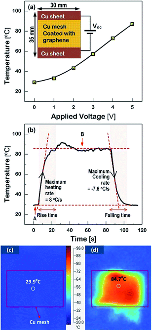
The graphene-coated Cu mesh electrodes fabricated on the corona-treated PET substrates were used to manufacture the flexible film heaters. Fig. 8(a) shows the temperature versus applied voltage relationship, along with the measurement schematic. The steady state temperature of graphene-coated Cu mesh with the Rsh value of about 15 Ω □−1 increased almost linearly with the applied voltage. This was based on Joule-heating: P = V2/R, where V is the applied voltage and R the total resistance. The applied power density was calculated to be about 0.53 W cm−2 at the applied voltage of 5 V.Fig. 8(b) displays the temperature profile of the film heater when the input voltage of 5 V was applied, as a function of the operation time. The heating and cooling rates were calculated from the temperature derivatives, which were about 8.0 °C s−1 and −7.6 °C s−1 respectively.
The room temperature before turn-on was measured at the region A, which was about 29.9 °C. Also, the steady state temperature was measured at the region B, which was about 84.7 °C. Both the rise time after turn-on and the falling time after turn-off were shorter than 20 s. This was due to the high heating and cooling rate of the Cu mesh electrode. The thermal images with the heating area of about 3.16 cm2 before and after operation are shown in Fig. 8(c) and (d) respectively. Accordingly, it is suggested that the graphene-coated Cu mesh electrodes fabricated in this study possess the improved visibility and high flexibility as well as the thermal characteristics, such as the heating capability of 85 °C at 5 V and the response time of shorter than 20 s, which would be desirable for flexible film heater application.
Experimental
Method of corona-treatment
Fig. S3† shows the schematic of the corona discharge system used in this study. The corona discharge was generated by applying 8 kV voltage to a corona electrode with a width of 190 mm. The PET substrate passed between two electrodes (i.e., the corona electrode and the grounded electrode) at a specified speed for surface treatment. The corona energy was controlled by varying the number of corona-treatment with the substrate feeding speed fixed at 0.027 m s−1, as also displayed in Fig. S3.†Electroless plating of Cu
The electroless plating was progressed through several steps in order, such as cleaning, pre-dip, activation, reduction, and plating, by preparing the solutions (ROHAR-202, ROHAR-470PD, ROHAR-470, ROHAR-570, and ROHAR-880, HANGARAM CHEMISTRY Co.) for each step. The organic contaminants were removed using a cleaner at 45 °C for 180 s before corona treatment. The corona-treated PET substrates were dipped into the pr-dip and activation solutions for the absorption of palladium (Pd) ions on the PET surfaces. Then, the Pd ions (Pd+2) were reduced to Pd metal (Pd0) used as the catalyst in the reduction process. Finally, the Pd served to reduce Cu ion (Cu2+) on the PET surface in the plating process for 420 s.Grid mesh pattering process
Cu grid meshes were prepared via photolithography and chemical etching according to the following processes. A photoresist (PR) was deposited on the Cu film via spin coating for 1 min at 5000 rpm to produce a 2.1–2.3 μm thickness. Baking was performed for 180 s in a hot plate at 100 °C. The grid pattern was formed on the PR layer through exposing UV and developing. Then, the Cu film was dipped into the etching solution, which was prepared by mixing the acetic acid (CH3COOH), hydrogen peroxide (H2O2), and DI water at a 1![[thin space (1/6-em)]](https://www.rsc.org/images/entities/char_2009.gif) :
:![[thin space (1/6-em)]](https://www.rsc.org/images/entities/char_2009.gif) 1
1![[thin space (1/6-em)]](https://www.rsc.org/images/entities/char_2009.gif) :
:![[thin space (1/6-em)]](https://www.rsc.org/images/entities/char_2009.gif) 10 volume ratio. Finally, the Cu layer was patterned to have a mesh dimension with a 200 μm line-to-line spacing and a 6 μm line width after stripping the residual PR.
10 volume ratio. Finally, the Cu layer was patterned to have a mesh dimension with a 200 μm line-to-line spacing and a 6 μm line width after stripping the residual PR.
Graphene coating
The graphene suspension (N-BaroTech, ER-4400) was prepared through the following purification and dispersion processes. The graphene was placed in a mixture of H2SO4 (20 ml) and HNO3 (10 ml) at a 2![[thin space (1/6-em)]](https://www.rsc.org/images/entities/char_2009.gif) :
:![[thin space (1/6-em)]](https://www.rsc.org/images/entities/char_2009.gif) 1 volume ratio and ultrasonicated for 30 min to eliminate impurities, such as metal catalysts and amorphous carbons. The graphene solution was filtered out using a vacuum filtering system and dispersed for 15 min using an ultrasonic generator after adding a dispersant of magnesium nitrate (Mg(NO3)2·6H2O, 15 mg) and isopropyl alcohol (IPA, 200 ml). The well-dispersed supernatant was extracted by operating a centrifugal separator at a 3000 rpm speed for 10 min. The graphene was coated on the Cu meshes deposited on the 7-times corona-treated PET substrates via EPD process, where a cathode (Cu mesh) and an anode (ITO-coated glass) were immersed in the graphene suspension and an electric current of 2 mA was applied to the two electrodes with the electrode-spacing fixed at 5 mm. The thickness of the graphene was controlled by varying the EPD time from 7 s to 15 s.
1 volume ratio and ultrasonicated for 30 min to eliminate impurities, such as metal catalysts and amorphous carbons. The graphene solution was filtered out using a vacuum filtering system and dispersed for 15 min using an ultrasonic generator after adding a dispersant of magnesium nitrate (Mg(NO3)2·6H2O, 15 mg) and isopropyl alcohol (IPA, 200 ml). The well-dispersed supernatant was extracted by operating a centrifugal separator at a 3000 rpm speed for 10 min. The graphene was coated on the Cu meshes deposited on the 7-times corona-treated PET substrates via EPD process, where a cathode (Cu mesh) and an anode (ITO-coated glass) were immersed in the graphene suspension and an electric current of 2 mA was applied to the two electrodes with the electrode-spacing fixed at 5 mm. The thickness of the graphene was controlled by varying the EPD time from 7 s to 15 s.
Characterization of PET substrates and Cu meshes
The contact angles of the PET substrates were measured with both water as a polar liquid and diiodomethane as a nonpolar or dispersive liquid using dynamic contact angle (DCA, SEO, Phoenix 300) equipment. The atomic force microscopy (AFM, Park System, XE-100) was used to measure the change in the surface roughness of the PET substrates after corona treatment. The thickness of each layer in the electrode was measured using a stylus profilometer (BRUKER, Dektak XT). The field emission scanning electron microscopy (FESEM, Sigma, Carl Zeiss) was used to observe the surface morphology of PET substrates, Cu meshes, and graphene coating layers. The sheet resistance was measured using non-contact sheet resistance measurement equipment (NAPSON, EC-80P). The transmittance, reflectance, and chromatic parameters (e.g., redness, yellowness) were measured in the 300–700 nm wavelength range using a spectrum colorimeter (Konica Minolta, CM-5). Also, the flexibility of the mesh electrodes was inspected by performing a bending test (JUNIL Tech, JIBT-200) and custom-made twisting test (MIREA B & S) equipment and also by measuring the adhesion strength between the Cu layers and the PET substrates using a scratch tester (Anton Paar, NST3). Finally, the thermal characteristics of film heaters employing the Cu meshes prepared in this study were measured using an infrared ray camera (Fluke, Tis10) by varying the input voltage from 1 V to 5 V.Conclusions
The graphene-coated Cu mesh electrodes were fabricated on the corona-treated PET substrates. The results of the contact angle and surface energy indicated that the surface condition of the PET substrates changed from hydrophobic to hydrophilic after corona treatment. It was also discovered that the surface roughness of the PET substrate was increased by increasing the number of corona treatments, which served as the anchor for strengthening the adhesive force between the PET substrate and the overlying Cu layer. Furthermore, the results regarding the changes in the sheet resistance due to the repetitive application of bending (up to 30![[thin space (1/6-em)]](https://www.rsc.org/images/entities/char_2009.gif) 000 times) and twisting (up to 10
000 times) and twisting (up to 10![[thin space (1/6-em)]](https://www.rsc.org/images/entities/char_2009.gif) 000 times) confirmed that the flexibility of the Cu mesh electrodes was substantially improved by increasing the numbers of corona treatments for the PET substrates. Coating the Cu mesh with graphene significantly reduced the reflectance and yielded a color difference approaching zero (i.e., colorless), while it slightly decreased the transmittance. Finally, the flexible film heaters were manufactured by employing the Cu-meshes, which were deposited on the corona-treated PET substrates and coated with graphene, and the film heaters revealed a heating capability of 85 °C or higher at the applied input voltage of 5 V and a response time of shorter than 20 s.
000 times) confirmed that the flexibility of the Cu mesh electrodes was substantially improved by increasing the numbers of corona treatments for the PET substrates. Coating the Cu mesh with graphene significantly reduced the reflectance and yielded a color difference approaching zero (i.e., colorless), while it slightly decreased the transmittance. Finally, the flexible film heaters were manufactured by employing the Cu-meshes, which were deposited on the corona-treated PET substrates and coated with graphene, and the film heaters revealed a heating capability of 85 °C or higher at the applied input voltage of 5 V and a response time of shorter than 20 s.
Conflicts of interest
There are no conflicts to declare.Acknowledgements
This research was supported by the BK21PLUS Program (No. 22A20130012328) and Basic Science Research Program through a National Research Foundation of Korea (NRF) (No. 2017R1D1A1B03028306).References
- C. H. Kim, W. J. Choi, S. K. Cho, D. Goshima, D. S. Ham, K. J. Kim, J. Jeong, J. H. Lee and S. J. Lee, Plasma Processes Polym., 2015, 12, 1322–1327 CrossRef CAS.
- Y. Kim, G. J. Jeon, M. K. Lee, S. H. Lee and S. H. K. Park, ECS Trans., 2016, 10, 247–251 CrossRef.
- K. A. Bush, C. D. Bailie, Y. Chen, A. R. Bowring, W. Wang, W. Ma, T. Leijtens, F. Moghadam and M. D. McGehee, Adv. Mater., 2016, 28, 3937–3943 CrossRef CAS PubMed.
- C. Chen, L. Ling and F. Li, Nanoscale Res. Lett., 2017, 12, 1–7 CrossRef PubMed.
- E. H. Ko, H. J. Kim, S. J. Lee, J. H. Lee and H. K. Kim, RSC Adv., 2016, 6, 46634–46642 RSC.
- X. He, A. Liu, X. Hu, M. Song, F. Duan, Q. Lan, J. Xiao, J. Liu, M. Zhang, Y. Chen and Q. Zeng, Nanotechnology, 2016, 27, 475709 CrossRef PubMed.
- C. H. Song, K. H. Ok, C. J. Lee, Y. Kim, M. G. Kwak, C. J. Han, N. Kim, B. K. Ju and J. W. Kim, Org. Electron., 2015, 17, 208–215 CrossRef CAS.
- C. H. Moon, IEEE Trans. Plasma Sci., 2010, 38, 2445–2450 CrossRef CAS.
- M. Cann, M. J. Large, S. J. Henley, D. Milne, T. Sato, H. Chan, I. Jurewicz and A. B. Dalton, Mater. Today Commun., 2016, 7, 42–50 CrossRef CAS.
- K. J. Singh, T. J. Singh, D. Chettri and S. K. Sarkar, Optik, 2017, 135, 256–270 CrossRef CAS.
- B. J. Kim, S. H. Han and J. S. Park, Surf. Coat. Technol., 2015, 271, 22–26 CrossRef CAS.
- J. Huo, J. Wu, M. Zheng, Y. Tu and Z. Lan, Electrochim. Acta, 2016, 187, 210–217 CrossRef CAS.
- S. Ji, S. J. Kim, W. Song, S. Myung, J. Heo, J. Lim, K. S. An and S. S. Lee, RSC Adv., 2016, 6, 19372–19376 RSC.
- X. Zhang, J. Wu, J. Wang, J. Zhang, Q. Yang, Y. Fu and Z. Xie, Sol. Energy Mater. Sol. Cells, 2016, 144, 143–149 CrossRef CAS.
- S. Xiao, C. Liu, L. Chen, L. Tan and Y. Chen, J. Mater. Chem. A, 2015, 3, 22316–22324 CAS.
- A. T. Bellew, H. G. Manning, C. Gomes da Rocha, M. S. Ferreira and J. J. Boland, ACS Nano, 2015, 9, 11422–11429 CrossRef CAS PubMed.
- K. Mallikarjuna, H. J. Hwang, W. H. Chung and H. S. Kim, RSC Adv., 2016, 6, 4770–4779 RSC.
- D. Lordan, M. Burke, M. Manning, A. Martin, A. Amann, D. O'Connell, R. Murphy, C. Lyons and A. J. Quinn, ACS Appl. Mater. Interfaces, 2017, 9, 4932–4940 CAS.
- W. Kim, S. Kim, I. Kang, M. S. Jung, S. J. Kim, J. K. Kim, S. M. Cho, J. H. Kim and J. H. Park, ChemSusChem, 2016, 9, 1042–1049 CrossRef CAS PubMed.
- T. Matsumoto, T. Koizumi, Y. Kawakami, K. Okamoto and M. Tomita, Opt. Express, 2013, 21, 30964–30974 CrossRef PubMed.
- J. Song and H. Zeng, Angew. Chem., Int. Ed., 2015, 54, 9760–9774 CrossRef CAS PubMed.
- C. M. Gabardo, R. C. Adams-McGavin, B. C. Fung, E. J. Mahoney, Q. Fang and L. Soleymani, Sci. Rep., 2017, 7, 1–9 CrossRef PubMed.
- A. Bouhamed, A. M. Kia, S. Naifar, V. Dzhagan, C. Müller, D. R. T. Zahn, S. Choura and O. Kanoun, Appl. Surf. Sci., 2017, 422, 420–429 CrossRef CAS.
- D. K. Owens and R. C. Wendt, J. Appl. Polym. Sci., 1969, 13, 1741–1747 CrossRef CAS.
- R. Shishoo, Plasma Technologies for Textiles, Elsevier Science, 2007 Search PubMed.
- S. H. Han, B. J. Kim and J. S. Park, Surf. Coat. Technol., 2015, 271, 100–105 CrossRef CAS.
- Z. Liu, J. Zhao, W. Xu, L. Qian, S. Nie and Z. Cui, ACS Appl. Mater. Interfaces, 2014, 6, 9997–10004 CAS.
- M. Connor, J. E. Bidaux and J. A. E. Månson, J. Mater. Sci., 1997, 32, 5059–5067 CrossRef CAS.
- E. Becker, Color Res. Appl., 2002, 27, 456 CrossRef.
- B. J. Kim, Y. J. Hwang and J. S. Park, Nanotechnology, 2017, 28, 165201 CrossRef PubMed.
Footnote |
| † Electronic supplementary information (ESI) available: The photos of Cu films on PET substrates, the variations in the sheet resistances of Cu films, the wetting energy, the schematic of corona treatment system and corona energy density. See DOI: 10.1039/c7ra09921e |
| This journal is © The Royal Society of Chemistry 2017 |

