
 Open Access Article
 This Open Access Article is licensed under a Creative Commons Attribution-Non Commercial 3.0 Unported Licence
In-liquid plasma: a novel tool in the fabrication of nanomaterials and in the treatment of wastewaters
S. Horikoshi
 *ab and
N. Serpone
c
*ab and
N. Serpone
c
aDepartment of Materials and Life Sciences, Faculty of Science and Technology, Sophia University, 7-1 Kioicho, Chiyodaku, Tokyo 102-8554, Japan. E-mail: horikosi@sophia.ac.jp
bMicrowave Science Research Center (MSRC), Sophia University, 7-1 Kioicho, Chiyodaku, Tokyo 102-8554, Japan
cPhotoGreen Laboratory, Dipartimento di Chimica, Università di Pavia, Via Taramelli 12, Pavia 27100, Italy. E-mail: nick.serpone@unipv.it
First published on 6th October 2017
Abstract
Attempts to generate plasma in liquids have been successful and various devices have been proposed. Many reports have described the optimal conditions needed to generate plasma, and mechanisms have been inferred, together with the composition of the plasma. Elucidation of a stable method (and mechanism) to generate plasma in liquids has led to various active investigations into applications of this new energy source. This review article describes the generator and the generation mechanism of in-liquid plasma, and pays attention to the evolving technology. The characteristics of submerged plasma are summarized and examples of nanomaterials syntheses and wastewater treatment are given, both of which have attracted significant attention. Extreme reaction fields can be produced conveniently using electrical power even without the use of chemical substances and high-temperature high-pressure vessels. Chemical reactions can be carried out and environmental remediation processes achieved with high efficiency and operability with the use of in-liquid plasma. Suggestions for introducing in-liquid plasma to chemical processes are discussed.
 S. Horikoshi | Satoshi Horikoshi (PhD 1999 Meisei University, Tokyo): Associate Professor at Sophia University since 2011 and currently Director of the Japan Society of Electromagnetic Wave Energy Applications (JEMEA); he is on Editorial Advisory Boards of the Journal of Microwave Power and Electromagnetic Energy and three international journals. Research interests involve new functional materials, nanomaterials synthesis, molecular biology, formation of sustainable energy, and environmental protection using microwave- and/or photo-energy, and co-author of over 180 scientific publications and contributor to and editor/co-editor of 23 books. He is a microwave specialist who often introduces effective methods of using microwave ovens at home on television. |
 N. Serpone | Nick Serpone (PhD, Cornell University, 1968) is a Visiting Professor at the University of Pavia, Italy, a Fellow of the European Academy of Sciences in the Division of Material Sciences, and is currently Head of the Materials Sciences Division of the Academy and Member of the Academy's General Board. His current research interests focus on the photophysics and photochemistry of metal-oxide semiconductors, heterogeneous photocatalysis, photochemistry of sunscreens. He has co-authored over 450 articles and co-edited several monographs. His work has been cited over 34 000 times (h-index factor = 93). |
1. Introduction
1.1 In-liquid plasma: a novel energy source for chemical reactions
Many chemists think it is strange that as much as or more than 99% of the substances present in the Universe exist as plasma, whereas the typical gas, solid and liquid states of matter tend to be rather rare in that environment. Compared to the vast scale of the Universe, chemists manufacture products in these states (gas, solid, liquid) with very limited materials. Human beings have used plasmas (e.g., the sun and fire) as energy sources for millennia. These classical energy sources have been used in early chemical syntheses and chemical analyses, even though they are difficult to control in the manufacturing process. Accordingly, electrically powered heaters and steam have been used in carrying out chemical reactions. More recently, microwave chemistry has developed significantly in the use of microwaves as the energy source.1 After World War II, the science behind changing substances artificially into plasma and then using this energy source in chemical reactions has been explored actively. However, combinations of plasma and chemical reactions have been limited to solid-phase reactions. Since ordinary plasma mimics a gas, its utilization in the liquid phase has only been possible in irradiating the liquid surface of a sample. Even with strong stirring, the effect of plasma on a liquid sample is not so pronounced. Nonetheless, chemists have considered using plasma as the energy source to activate chemical reactions, even though its use is difficult from the productivity viewpoint.Recent years have also witnessed the successful generation of stable plasma in solution (referred to as in-liquid plasma); its application in various fields is currently being investigated. Use of in-liquid plasma has attracted significant attention as being a hot research topic. The state of new substances generated in liquids is expected to be a new tool in solution chemistry fostered by a combination of innovative ideas and the promise of novel materials synthesis. For instance, in-liquid plasma could be applied to fuel (hydrogen) recovery from a methane hydrate layer existing in Japanese waters; the method used is detailed in Fig. 1.2 It involves irradiating a methane hydrate layer with in-liquid plasma to achieve dehydrogenation reaction and recover hydrogen energy from bubbles deep in oceanic waters. In the existing method, the methane hydrate is recovered using a pump; however, it is possible to recover the required amount of hydrogen from the seabed without the use of pumps. Depending on conditions, in-liquid plasma can drive various chemical processes.
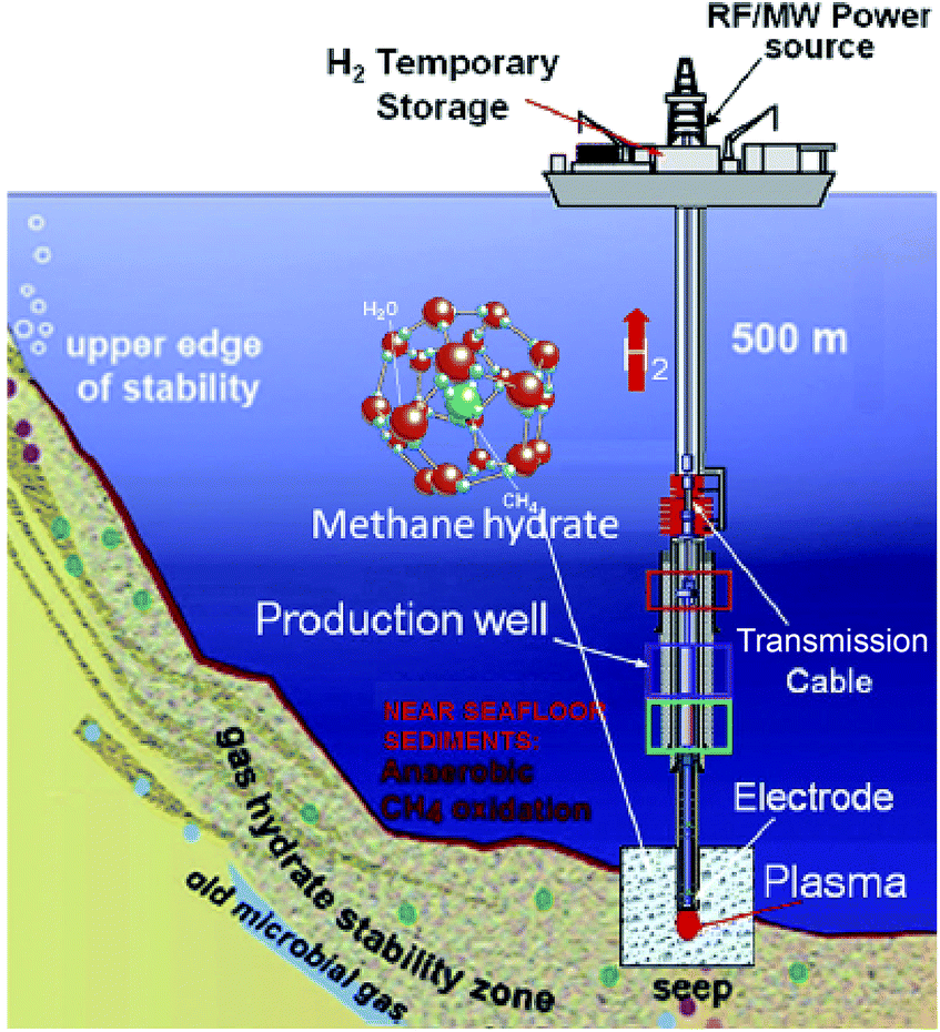 | ||
| Fig. 1 Process for hydrogen production from hydrate fields in subsea sites using the plasma from the in-liquid method. Reproduced from Rahim and coworkers.2 Copyright 2015 by Elsevier. | ||
1.2 Plasma
Although plasma is an emerging technology in many fields of application, the history of plasma technology goes as far back as the 18th century. Georg Christoph Lichtenberg (1742–1799), a professor of mathematics in Göttingen (Germany), produced brush discharges by spreading fern spores between two electrodes.3Michael Faraday (1791–1867), discoverer of electromagnetism in 1821, was the first to provide an explanation for Lichtenberg's observations. His countryman, Sir William Crookes (1832–1919), later discovered the fourth state of matter as radiating matter in discharge tubes,4 which he correctly assumed to consist of electrically charged gas molecules in the tubes: de facto, plasma was born. He later defined it in his lecture titled “On Radiant Matter” delivered before the British Association for the Advancement of Science, on 22 August 1879 at Sheffield (D. Appleton, The Popular Science Monthly, 1880, Volume 16, pp 157–167). Crookes discovery was followed nearly two decades later (1897) by Sir Joseph John Thomson's (1856–1940) postulation that atoms consist of positively charged electrons that possess a mass.5 This was also confirmed by the German chemist Eugen Goldstein, who discovered that the so-called canal rays consisted of positively charged particles with missing electrons (H+ ions from hydrogen gas). Thus, plasma had been identified as a mixture of electrons and ions. The term plasma was finally defined by the American chemist Irving Langmuir (1881–1957) who in 1923 observed specific oscillations in an ionized gas that he referred to as plasma oscillations generated from an inhomogeneous charge distribution and to the natural tendency of the charge to redistribute uniformly inside the plasma.6 The first comprehensive published report on gas discharges was by the German physicist Johannes Stark (Die Elektrizität in Gasen), then Director of the Institute of Physics of the University of Greifswald. Stark was awarded the 1919 Nobel Prize for the discovery of the Doppler Effect in canal rays and for the splitting of the spectral lines in electric fields (the Stark Effect). At the end of 1918, Stark invited Rudolf Seeliger to the University of Greifswald who remained until 1955. Seeliger is one of the pioneers of modern plasma and gas-discharge physics. The fundamental physical properties of plasma were clarified in the first half of the 20th century by Seeliger and others, which led to rapid advances in the engineering applications of plasmas,7 as exemplified by the inventions of the mercury discharge lamp (Cooper Hewitt light: 1902), the mercury arc lamp (1905), and the high-pressure mercury lamp (1906) among others.
Coupling theory and technological innovations in plasma applications also advanced noticeably. In the second half of the 20th century, plasmas were used increasingly for a variety of purposes, such as in neon tubes (vacuum) and in etching processes (hot). Technological progress in the mid-1990s also led plasmas to be generated non-thermally under atmospheric pressure, which opened loads of new possibilities since expensive and complex vacuum systems were no longer needed; processes could now be run continuously without putting stress on materials being treated. As a result, plasma-induced processes could then be applied in, for instance, the medical sector for the gentle sterilization of medical equipment and catheters. In 1996, Laroussi8 was one of the first to describe a novel sterilization method that used uniform glow discharge plasma generated at atmospheric pressure. He examined the inactivation of Pseudomonas fluorescens bacteria in yeast extract in a polypeptone glucose solution.
Starting with a handful of publications in the mid-1990s, the number of publications that dealt with applications of plasmas increased rapidly at the turn of the 21st century. Indeed, the total number of publications dealing with cold plasma has increased significantly in the past 20 years, attesting to the importance of this emerging technology. As we speak, various engineering application advances are being made. This indispensable technology has developed and currently used extensively in metal welding, in surface treatments, in the processing of materials and electronic components, in the fabrication of nanomaterials, and in wastewater treatment (among others).6
Plasma is classified as (i) high-temperature plasma (thermal equilibrium plasma), and (ii) as low-temperature plasma (non-thermal equilibrium plasma). Thermal equilibrium plasma is plasma generated by applying electrical power for a long time under conditions that the gas pressure is 5 kPa or more, and that the electron and gas temperatures are nearly equal. Since the ionization energy of atoms and molecules necessitates several eV or more (tens of thousands of degrees Celsius), some of the electrons and ions become high-energy particles. In general, the materials temperature in thermal equilibrium plasma reaches as much as several thousand degrees Celsius or more; this plasma is casually used as a heat source and light source for welding and lamps. By comparison, the electron temperature is higher than the gas temperature in non-thermal equilibrium plasma. For example, to convert a gas molecule into non-thermal equilibrium plasma, heat transfer to ions and molecules can be restricted by setting gas molecules to a reduced pressure state and by lowering the frequency of collision of electrons with ions or molecules. A characteristic of non-thermal equilibrium plasma is that its gas temperature is low and electrons are in a high-energy state, and as such it is used in the manufacturing of semiconductors and films through chemical reactions. Since non-thermal equilibrium plasma must maintain reduced pressure conditions, facilities such as a vacuum chamber and a vacuum evacuation device are required, even if plasma were generated by a short pulse discharge under atmospheric pressure conditions. This is often referred to as atmospheric pressure non-thermal equilibrium plasma because it has different properties from the plasma in vacuum.
2. In-liquid plasma
2.1 Why plasma can be generated in a liquid (and in a solid)
Since plasma is a state of matter generated by a destabilizing gas, one must ask whether plasma can also form in solids and liquids. Some people are still sceptical about this. | ||
| Fig. 2 Relationship between plasma and the three states of matter. | ||
There are two key methods of generating in-liquid plasma. The first key method is an underwater streamer discharge that produces linear plasma in the liquid; the dielectric breakdown of the liquid turns into a type of corona discharge considering the classification of general plasma. During the dielectric breakdown of water, micro-bubbles are formed near the electrode by cavitation produced either by a high electric field or by heating from a conductive current; the plasma is generated in the micro-bubble.12 To generate an underwater streamer discharge, even in an aqueous solution, an electrical power of 50 to 400 kV and a current of 100 A or more are required. Industrially, it is difficult to achieve and maintain a steady-state electrical power of this magnitude from the viewpoint of stability and energy saving. Accordingly, many discharges are generated using a pulsed voltage of 1 μs duration or less. An underwater streamer discharge occurs in liquid at a rate of 30 to 100 mm μs−1 while the liquid is being vaporized at the liquid/air interface.14,15 The occurrence of an underwater streamer discharge in the liquid phase generates ultraviolet rays, shock waves, and localized heat, together with chemically active species formed by the resulting plasma.16 The second key method is to generate bubbles by heating, by shock waves, and by gas introduction (or the like) in the liquid to create in-liquid plasma. Since applying electrical power is not always accompanied by a dielectric breakdown of the liquid, in many cases plasma can still be generated with a power of 10 kW or less as a glow discharge, a corona discharge (streamer discharge), and as an arc discharge.
Except for underwater streamer discharge, this review article will restrict its considerations to all in-liquid plasmas as plasma generated in bubbles contained within the liquid.
 | ||
| Fig. 3 (a) Photograph illustrating the generation of plasma in liquid using a microwave power supply; (b) spectrum of ultraviolet and visible light emitted by in-liquid plasma generated in ion-exchanged water. Taken from ref. 17. Copyright 2017 by S. Horikoshi. | ||
2.2 Methods to generate in-liquid plasma
Fig. 4a shows near surface interactions with plasmas generated outside the liquid.19 From the cocktail of plasma, such species as radicals, ions, electrons and photons are thought to interact, to differing degrees, with the liquid interface, thereby initiating reactions that cascade well into the liquid phase, possibly via biochemical pathways (Fig. 4a). Radicals, ions and photons are often considered, but in attempts to isolate important sources of reactions within liquids, it is also necessary to consider electron interactions directly with the liquid phase (Fig. 4b and c); to date, these have received little attention. Accordingly, the focus of this paper will be restricted to phenomena occurring under plasma conditions as illustrated in Fig. 4b and c. | ||
| Fig. 4 Schematic diagram of three different types of plasma in-liquid conditions (PiLC): (a) gas-phase species and plasma-radiation-induced liquid reactions at the plasma–liquid interface; (b and c) electrons from the plasma can initiate non-equilibrium reactions in the liquid phase where both electron energy distribution (b) and electron density play an important and distinct role (c). Reproduced from Mariotti et al.19 Copyright 2012 by WILEY-VCH. | ||
Currently, methods to generate in-liquid plasma can be broadly divided into four categories, and since each possesses its own characteristics, it is necessary to select the appropriate plasma according to purpose and end-use. Considering electrode configurations and energy sources, generated in-liquid plasma can be subdivided as:
(1) Plasma A: direct discharge between two electrodes using an AC (plus) power supply.
(2) Plasma B: contact discharge between an electrode and the surface of the surrounding electrolyte using a DC power supply.
(3) Plasma C: plasma generated with either radio frequency (RF) or microwave (MW) irradiation.
(4) Plasma D: plasma generated using the laser ablation technique.
The schematic of generating Plasma A involves a direct discharge between two electrodes that comes in such forms as solution plasma, discharge plasma in liquid, electric spark discharge, arc discharge, capillary discharge, and streamer discharge (Fig. 5a). Two electrodes of similar size and shape are immersed in the liquid at a short distance. Because of the direct discharge, most liquids containing conductive electrolytes in such media as deionized water, ethanol, and liquid nitrogen can be used. Thus, in-liquid plasma is generated between the two electrodes immersed in the electrolyte solution after passing an electric current through the solution. It is important that the liquid used in this method be conductive.
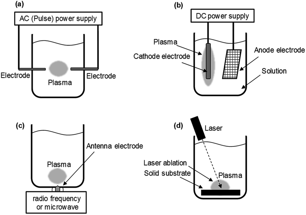 | ||
| Fig. 5 Images of plasma generation method in a liquid: (a) direct discharge between two electrodes using an AC (plus) power supply; (b) contact discharge between an electrode and the surface of the surrounding electrolyte using a DC power supply; (c) plasma generation with radio frequency (RF) or microwave (MW) irradiation; (d) plasma generation using the laser ablation method. | ||
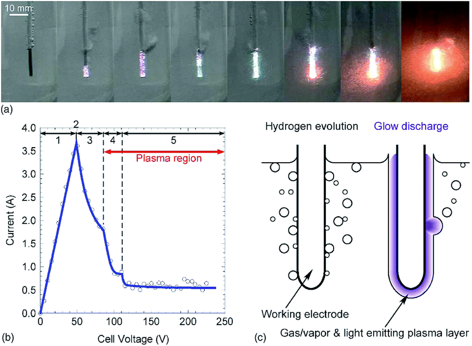
The schematic of Plasma B is displayed in Fig. 5b. In 1963, Hickling and Ingram reported contact glow discharge electrolysis (CGDE),20 whereby a high-temperature plasma sheath formed between an electrode and the surface of the surrounding electrolyte as a result of a high electric field; this was subsequently accompanied by a glow discharge photoemission. Consider now two electrodes immersed in a conductive electrolyte in which the distance between them is varied from 5 mm to over 100 mm, and the electrode surface area between the anode and cathode is different; one of the electrodes has a smaller surface area than the other. The electrode with the smaller surface area is covered with a thin film of water vapor within which a discharge occurs. In a submerged plasma two-electrode generator that uses a direct current power supply, passing the electric current through the electrolyte liquid produces foam owing to Joule heating; the in-liquid plasma is generated at the cathode side. In such a system, as the conductivity of the liquid changes, the conditions under which the in-liquid plasma is generated also change, so that it is necessary to keep the conductivity at an appropriate level. In most cases, the cathode consists of a metal plate with a large surface area (e.g., a Pt mesh), while the anode is a metal wire. A stable DC power supply is often used, although pulsed DC has also been used.
Techniques for generating in-liquid plasma by irradiating an antenna electrode with radio frequency or microwaves for Plasma C have been utilized in a variety of fields (Fig. 5c). These techniques are effective in generating in-liquid plasma at a lower electrical power. In the plasma generating apparatus, the dielectric constant and the dielectric loss of the liquid are important factors in the generation process. Unlike other techniques, however, it is not necessary to use an electrolyte solution. Radio frequency or microwave generated in-liquid plasma can be maintained in water over a wide range of water conductivity (from 0.2 to 7000 mS m−1). When plasma is generated in a solution using radio frequency or microwaves, a lower pressure is often applied because energy is absorbed by water as it possesses a dielectric constant and dielectric loss. An advantage here is that plasma can be generated even in pure water, and so various application developments can be expected.
Another method for generating plasma in a liquid uses the laser ablation technique (Plasma D; Fig. 5d). The laser irradiates a solid substrate immersed in the liquid causing a plasma ball to be generated on the surface of the solid. This technology is applied in such research as nanoparticle production21 and deep-sea mass spectrometry.22
The various techniques for generating Plasma A–C proposed according to usage conditions, reaction conditions, and operating equipment (among others) have been classified in some detail by Saito and Akiyama23 who explained the classification based on the corresponding engineering diagram for the Plasma A–C summarized in Fig. 6,23–84 7,85–128 and 8.129–154
 | ||
| Fig. 6 Typical electrode configuration for Plasma A: (A-1) influence of glow discharge plasma and dielectric barrier discharge;24–30 (A-2) dielectric barrier discharge in quartz tube;31 (A-3) gliding arc discharge;32 (A-4) gas–liquid interfacial plasma, plasma electrochemistry in ionic liquids, and so forth;33–45 (A-5) glow discharge formation over water surface;46 (A-6) discharge electrolysis;47–64 (A-7) microplasma;19,65–75 (A-8) dual plasma electrolysis;76 (A-9) plasma in contact with liquids;77,78 (A-10) microplasma discharge;79 (A-11) glow discharge generated in contact with a flowing liquid cathode;80–84 (A-12) AC capillary discharge. Modified with permission from ref. 23. Copyright 2015 by Hindawi. | ||
 | ||
| Fig. 7 Typical electrode configuration for Plasma B: (B-1) contact glow discharge;85–108 (B-2) electrical discharges,109–111 streamer discharge plasma in water;112 (B-3) solution plasma,91,93,99,113 electric discharge plasma;114 (B-4) contact glow discharge;113,115,116 (B-5) contact glow discharge;117 (B-6) contact glow discharge electrolysis;118–120 (B-7) high-voltage cathodic polarization;121 (B-8) contact glow discharge electrolysis;118,122–125 and (B-9) electrical discharge.126–128 Modified with permission from ref. 23. Copyright 2015 by Hindawi. | ||
 | ||
| Fig. 8 Typical electrode configuration for Plasma C: (C-1) RF applied in-liquid plasma system under vacuum condition;129–140 (C-2) MW applied in-liquid plasma system under vacuum condition;134,141–149 (C-3) MW-induced in-liquid plasma system under atmosphere condition;150,151 (C-4) slot-excited MW discharge in-liquid plasma system under atmosphere condition;152 and (C-5) in-liquid plasma generation system with a MW oven.153,154 Modified with permission from ref. 23. Copyright 2015 by Hindawi. | ||
2.3 Problems and countermeasures in plasma generation
To generate plasma continuously in a liquid necessitates application of a large electrical power as compared to the case of generating plasma in vacuum or under atmospheric pressure, so that the thermal load on the electrode is large. Consequently, studies on electrodes used in plasma generation have been carried out for many years. In-liquid plasmas have been generated using electrodes made with such materials as tungsten, aluminum, copper, molybdenum, stainless steel (SUS 304), and carbon. Plasma generation with electrodes made of carbon, molybdenum, and SUS 304 lasted no more than 5 min.155 Moreover, continuous (for 10 min) in-liquid plasma generation with aluminum and copper electrodes caused deterioration of the electrode surface. On the other hand, for electrode material with high melting points (e.g., tungsten, mp = 3422 °C), the electrode could, in principle, withstand long-term use (Fig. 9). Nonetheless, deterioration of the electrode surface can still occur depending on the generation conditions of the in-liquid plasma. Therefore, studies on the mechanism of in-liquid plasma heating of the electrodes and improvement measures are ongoing. | ||
| Fig. 9 (a) Photograph of a tungsten pencil-type electrode of an in-liquid plasma generator of the microwave type in an unused state; (b) photograph of a tungsten pencil-type electrode after several minutes of generating in-liquid plasma with continuous microwaves. Taken from ref. 17. Copyright 2017 by S. Horikoshi. | ||
Many of the currently reported in-liquid plasmas produce bubbles within which plasma is generated in the liquid. However, if the bubble generating device were to be connected separately, the physical structure of the plasma generating portion would get rather complicated. To resolve this problem, an ultrasonic wave irradiation device is installed in the vicinity of the plasma generating electrode. Even with this method, however, it is not possible to improve the apparatus complexity in the vicinity where plasma is generated. Accordingly, an apparatus has been developed in which the electrode and the ultrasonic homogenizer horn are integrated.
For instance, by sharing the microwave antenna electrode with the ultrasonic homogenizer as an in-liquid plasma apparatus driven by a single microwave power supply, both microwaves and ultrasonic waves can be used to irradiate simultaneously, thereby simplifying the apparatus (Fig. 10).156 Since the ultrasonic homogenizer can generate fine bubbles in the liquid, they can be produced in the very vicinity where plasma is generated, causing plasma to be generated efficiently in the bubbles. Using the latter method, even if the incident power of the microwaves were reduced by 45% or more, compared to the existing apparatus without ultrasonic waves, in-liquid plasma could still be generated continuously and deterioration of the electrode could be minimized if not suppressed for long periods of use.
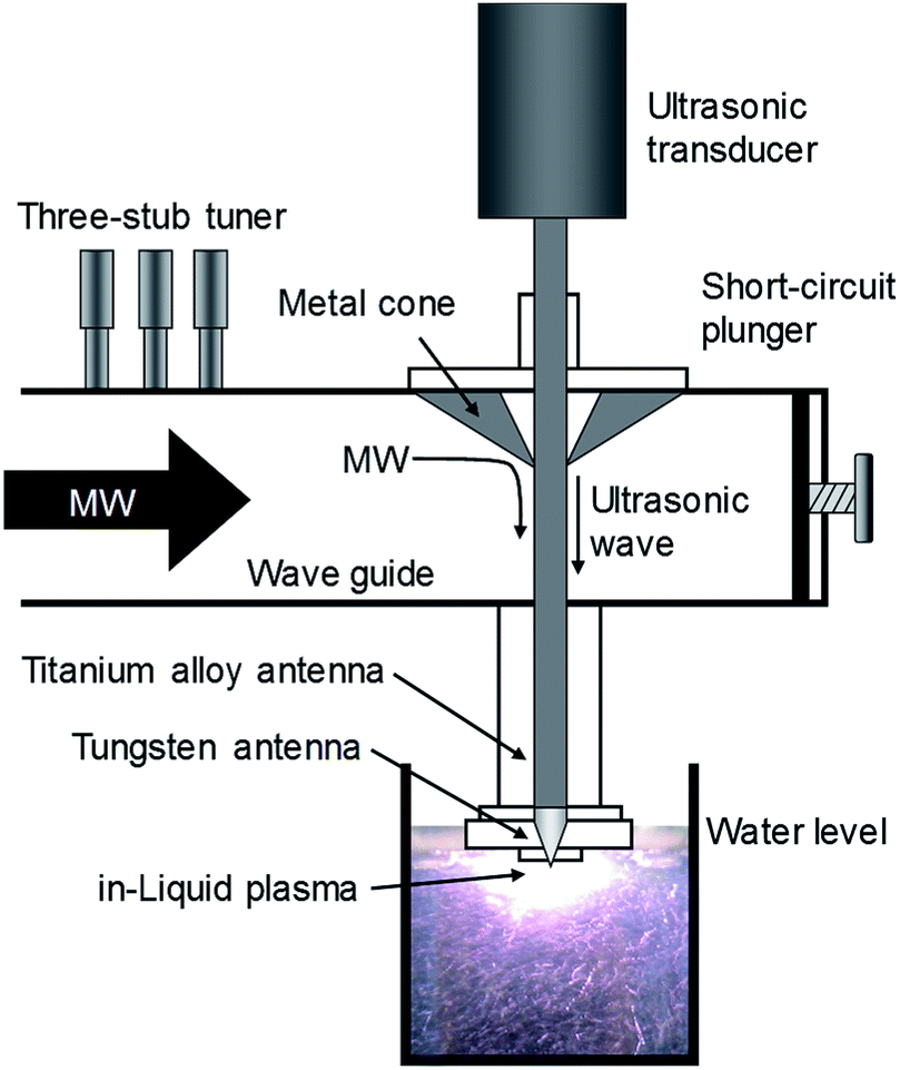 | ||
| Fig. 10 Schematic diagram of an ultrasonic/microwave simultaneous irradiation type in-liquid plasma generator system. Reproduced from Horikoshi et al.156 Copyright 2017 by Elsevier. | ||
3. In-liquid plasma applications
3.1 Nanomaterials synthesis
Dissolution of the electrode method. Studies have been conducted on the evaporation method to form various metallic nanoparticles by placing cathode electrodes of various metals in a potassium carbonate solution, followed by applying a direct current to this solution to evaporate and dissolve the electrodes. Metallic nanoparticles have been formed in solution during the evaporation of Ni, Ti, Ag, and Au nanowire electrodes with in-liquid plasma (Fig. 11).88 The advantage of this method is that various kinds of nanoparticles can easily be formed in a liquid by simply changing the kind of metal used for the wire electrode. Along similar lines, Saito and coworkers94 reported the syntheses of a single crystal tin oxide plate (SnO) and a Sn6O4(OH)4 skeleton using tin wire immersed in an electrolyte solution.
 | ||
| Fig. 11 (a) Photograph of plasma emission during the formation of nanoparticles; (b) relationship between current and voltage; (c) cartoon illustrating the process of nanoparticle generation. Reproduced from Toriyabe et al.88 Copyright 2007 by the American Institute of Physics. | ||
The size and shape of these nanoparticles can be controlled by changing the synthesis conditions (reaction temperature, cooling temperature, dispersant) of generating in-liquid plasma (Fig. 12).94 And even if plasma conditions were changed, the morphology and the nature of nanoparticles could still be controlled (Fig. 13).99 Metal electrodes can be volatilized using wide-area plasma, partial plasma, and partial plasma under high-temperature conditions. Accordingly, it is possible to produce Ti, Fe, Ni, Cu, Zn, Zr, Nb, Mo, Ag, W, Pt, Au, and SUS 316 nanoparticles using in-liquid plasma as the energy source. In addition, alloy nanoparticles of gold and platinum can be made by the simultaneous evaporation of the two electrode materials with in-liquid plasma (Fig. 14).157 Another study reported the evaporation of a platinum electrode with in-liquid plasma to produce platinum nanoparticles (particle size, 2 nm) supported on a highly conductive carbon black support dispersed in water.158 This Pt/C catalyst was produced with very high efficiency and used as a catalyst in fuel cells.
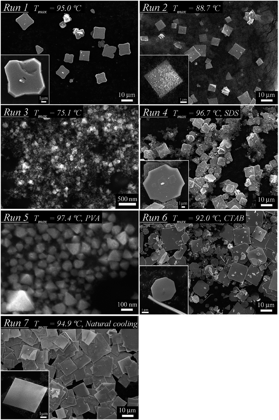 | ||
| Fig. 12 SEM images of single crystals of a tin oxide SnO plate synthesized by in-liquid plasma under different reaction temperatures, dispersant and cooling conditions. Reproduced from Saito et al.94 Copyright 2012 by the American Chemical Society. | ||
 | ||
| Fig. 13 Images of (a) a wide-area plasma; (b) a partial plasma; and (c) the volatilization of a metal electrode by partial plasma under high temperature conditions. Reproduced from Saito et al.99 Copyright 2014 by the American Institute of Physics. | ||
 | ||
| Fig. 14 Image of a synthesis apparatus of a gold/platinum alloy by in-liquid plasma using gold and platinum electrodes. Reproduced from Hua and coworkers.157 Copyright 2013 by Elsevier. | ||
Reduced reaction with plasma method. Zinc oxide nano-particles (ZnO NPs) have been produced using in-liquid plasma.90 In this case, a Zn wire (the cathode) and a mesh made of Pt wire (the anode) were submersed in an aqueous solution of K2CO3. Application of a certain voltage to the solution system generated plasma in the immersed part of the Zn wire. Using medium-power input levels resulted in the formation of flower-like ZnO NPs (Fig. 15a and b),90 while applying high-power input levels yielded aggregated ZnO NPs (Fig. 15c); the mechanism of the synthesis is summarized in Fig. 15d. The Zn wire is first oxidized to ZnO on its surface after plasma generation. At low power, the surface temperature of the electrode is below the melting point of zinc and some Zn(OH)42− species form around the Zn wire (reaction (1)).
| ZnO(s) + H2O + 2OH− → Zn(OH)42− | (1) |
 | ||
| Fig. 15 SEM images of products obtained from in-liquid plasma usage; experimental conditions of K2CO3 concentration, and discharge voltage/power are: (a) 1.0 M, 66 V/44 W, (b) 0.5 M, 80 V/48 W, (c) 0.01 M, 200 V/168 W. (d) Schematic processes in the synthesis of ZnO nanoflowers and ZnO aggregates using in-liquid plasma. Modified with permission from ref. 90. Copyright 2011 by Elsevier. | ||
Subsequently, Zn(OH)42− migrates to the low-temperature zone and decomposes into ZnO (reaction (2)).
| Zn(OH)42− → ZnO(s) + H2O + 2OH− | (2) |
The ZnO nanoparticles grow preferentially along the [0001] direction 159,160 to form the flower-like ZnO nanoparticles. However, at high power (i.e., at >300 W cm−2 (ref. 90)), the temperature of the Zn wire reaches its melting point causing rapid evaporation of the Zn wire and the ZnO film resulting in ZnO particle aggregates (Fig. 15c).
Research studies are also being conducted actively on a reduction method to synthesize various nanoparticles. For instance, gold-based bimetallic particles, (e.g., Au–Fe, Au–Ga, Au–In or the like) can be produced using a metal-ion reduction method and a metal nitrate as the precursor from bivalent sp metals, trivalent sp metals, or 3d and 4d metals. A one-step synthesis of nanoparticles in water has also been described.161 Stable gold bimetallic nanoparticles of 5 to 20 nm can be synthesized using this method. On the other hand, in the case of microwave-generated in-liquid plasma (2.45 GHz), Toyota and coworkers162 succeeded in depositing diamond particles (7 to 8 μm) onto silicon wafers to produce a diamond electrode in methanolic media. Syntheses of Cu, Au, and Pt nanoparticles by the in-liquid plasma reduction method have also been described.151
In fact, syntheses of nanomaterials have been reported extensively as there are many advantages in using the energy from in-liquid plasma to drive a chemical reaction. Thus, various nanoparticles of noble metals, alloys and metal-oxide nano-materials have been synthesized using various types of plasma-related techniques. Some of the nanoparticles, starting materials and type of in-liquid plasma used are summarized in Table 1.
| Nanoparticles produced | Starting materials | In-liquid plasma methods | Ref. |
|---|---|---|---|
| Au | Gold rod or wire | Plasma A | 165–169 |
| Plasma B | 88, 99 and 114 | ||
| Plasma C | 140 | ||
| HAuCl4 | Plasma A | 170–179 | |
| NaAuCl4 | Plasma B | 86 | |
| Ag | Silver rod or wire | Plasma A | 180–183 |
| Plasma B | 88 and 99 | ||
| Plasma C | 140, 147 and 151 | ||
| AgNO3 | Plasma A | 184 and 185 | |
| Ag-zeolite | Plasma A | 186 | |
| Pt | Platinum wire | Plasma A | 187 |
| Plasma B | 96 | ||
| Plasma C | 151 | ||
| H2PtCl6 | Plasma B | 86 | |
| Ni | Nickel wire | Plasma A | 96 |
| Plasma B | 88, 89, 96 and 106 | ||
| Cu | Copper wire | Plasma A | 188 |
| CuCl2 | Plasma A | 189 and 190 | |
| CuSO4 | Plasma B | 86 | |
| Ni | Nickel wire | Plasma A | 96 |
| Plasma B | 88, 89, 96 and 106 | ||
| Cu | Copper wire | Plasma A | 188 |
| CuCl2 | Plasma A | 189 and 190 | |
| CuSO4 | Plasma B | 86 | |
| Zn | Zinc plate | Plasma C | 144 |
| Sn | Tin rod | Plasma B | 98 and 101 |
| Pt–Au | Pt and Au wires | Plasma A | 157 |
| Pt–Au | H2PtCl6, NaAuCl4 | Plasma B | 86 |
| Ag–Pt | Ag and Pt rod | Plasma A | 191 |
| Ni–Cr | Alloy wire | Plasma B | 102 |
| Ni–Cu | Ni(NO3)2·6H2O, Cu(NO3)2·4H2O | Plasma A | 192 |
| Sn–Ag | Alloy wire | Plasma B | 114 |
| Sn–Pb | Alloy wire | Plasma B | 102 |
| Stainless steel | Alloy wire | Plasma B | 102 and 114 |
| Co–B | Cobalt acetate, KBH4 | Plasma A | 193 |
| MoS2 | MoS2 powder | Plasma A | 194 |
| γ-Al2O3 | Aluminum rod | Plasma A | 195 |
| Aluminum plate | Plasma B | 196 | |
| TiO2 | Titanium rod | Plasma A | 88, 95 and 197 |
| Plasma B | 109 | ||
| Defective black TiO2 | Ti wire | Plasma B | 198 |
| Pt nanoparticles supported on TiO2 nanotube | TiO2 nanotube and Pt wires | Plasma B | 199 |
| Cellulose–ZnO composite | Zn(O2CCH3)2·2H2O (or anhydrous Zn acetate) and D-glucose | Plasma A | 200 |
| CuO | Copper foil | Plasma B | 201 |
| Cu2O | Copper plate | Plasma B | 202 |
| In(OH)3 nanocubes | Indium and tin plate | Plasma B | 203 |
| Fullerene (C60) | Graphite in toluene | Plasma A | 204 |
| Carbon nanotubes (CNT) | Carbon rods | Plasma A | 205–209 |
| CNT-supported Pt nanoparticles | Pt, H2PtCl6, CNT | Plasma A | 210 |
| Carbon–metal nanocomposites | Platinum, aluminium, nickel, copper, tungsten, carbon electrodes | Plasma B | 211 |
| Ag on mesoporous silica | Ag NPs, tetraethylorthosilicate (TEOS) | Plasma A | 212 and 213 |
Panomsuwan and co-workers163 reported that metal-free N-doped carbon nanoparticles (NCNPs) could be synthesized via a solution plasma process with the potential to achieve uniformly distributed nitrogen atoms. Accordingly, they used a set of cyanoaromatic molecules that included benzonitrile, 2-cyanopyridine and cyanopyrazine as a single-source precursor in the synthesis without the addition of a metal catalyst. The resulting NCNPs revealed uniformly nanosized particles (20–40 nm) and an interconnected hierarchical pore structure with a high specific surface area (210–250 m2 g−1). The difference in carbon/nitrogen mol ratios of organic precursors gave rise to the variation of nitrogen-doping level in NCNPs from 0.63 to 1.94 atom%. A detailed electrochemical evaluation toward the oxygen reduction reaction (ORR) demonstrated that NCNPs exhibit a significant improvement in terms of both onset potential and current density under alkaline and acidic conditions. The predominant distribution of graphitic-N and pyridinic-N sites on NCNPs played an essential role in enhancing the ORR activity and the selectivity toward a four-electron reduction pathway. More importantly, NCNPs possessed excellent robust long-term durability and strong methanol tolerance compared with those of a commercial Pt/carbon catalyst. The possible formation mechanism of NCNPs is illustrated schematically in Fig. 16. After discharging for 30 min, black solid particles were separated from the liquid precursor by pouring through a filter paper and washed several times with ethanol until the wash solvent was colorless. The solution plasma approach used163 should broaden and accelerate further research efforts on nitrogen-doped carbon catalysts, one-step closer to practical fuel cells and other related electrochemical devices.
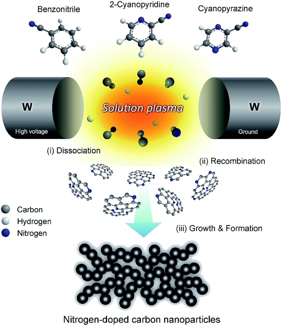 | ||
| Fig. 16 Schematic illustration of the formation mechanism of nitrogen-doped carbon nanoparticles (NCNPs) via a solution plasma process. Modified with permission from ref. 163. Copyright 2016 by Elsevier. | ||
Morishita and co-workers164 investigated the routes of solution-plasma-induced nanocarbon formation from hexane, hexadecane, cyclohexane, and benzene; the synthesis from benzene was the most effective. However, the nanocarbons obtained from linear molecules were more crystalline than those from ring molecules. Linear molecules decomposed into shorter olefins, whereas ring molecules were reconstructed in the plasma. C–H dissociation proceeded in the saturated ring molecules, followed by conversion into unsaturated ring molecules. However, unsaturated ring molecules were directly polymerized through cation radicals (e.g., benzene radical cation) and were converted into two- and three-ring molecules at the plasma–solution interface. The nanocarbons from linear molecules were synthesized in plasma from small C2 molecules under heat; the products so-obtained were the same as those obtained via a pyrolysis synthesis. Conversely, the nanocarbons obtained from ring molecules were directly synthesized through an intermediate (such as benzene radical cations) at the interface between the plasma and the solution, resulting in the same products as those obtained via polymerization. These two different reaction fields provide a reasonable explanation for the fastest synthesis rate observed in the case of benzene. Two reaction paths from monomer to polycyclic aromatic hydrocarbons (PAHs), including graphene, are displayed in Fig. 17. One reaction path (reaction path 1) is from the plasma center. The solution is vaporized by a strong electric field between the electrodes. The vaporized solution forms a gas phase between the electrodes, which is converted into plasma after breakdown. In the plasma, organic compounds were almost completely decomposed, and were similar to the products obtained via a pyrolysis synthesis.
 | ||
| Fig. 17 Reaction routes from hexane, hexadecane, cyclohexane, and benzene. Modified with permission from ref. 164. Copyright 2016 by the Nature Publishing Group. | ||
The most apparent result of this is the distinctive colors produced owing to different sizes of the nanocrystalline particles. Because of their small size, electrons in quantum dots are confined in small space (a quantum box). When the radii of the semiconductor nanocrystals are smaller than the exciton Bohr radius (exciton Bohr radius is the average distance between the electron in the conduction band and the hole it leaves behind in the valence band), the energy levels are quantized as per Pauli's exclusion principle. Because of the high level of control possible over the size of the nanocrystals produced, quantum dots can be tuned during the manufacturing process to emit light of various colors.216 These unique properties render quantum dots versatile in such applications as transistors, solar cells, LEDs, diode lasers, as well as in medical imaging and in quantum computing.217
Ultra-small sized (within 5 nm) and monodispersed silicon quantum dots (Si QDs) are ideal candidates for Si/C nano-composites to be used as anode materials in lithium ion batteries. However, fabrication of these Si QDs/C nanocomposites remains a gigantic challenge in materials chemistry because of the small size, high chemical activity, and low density of Si QDs with Si–H terminated surfaces. Nonetheless, Wei and coworkers218 reported a convenient synthetic method for the preparation of Si QDs/C nanocomposites by a novel liquid-phase plasma-assisted synthetic process, with the Si quantum dots embedded in a carbon matrix (Si-QDs/C) via a direct discharge between two electrodes powered by an AC power supply. Fig. 18a shows the setup for the liquid-phase plasma synthetic route.218 Briefly, the copper and the tungsten (with a quartz shell) electrodes were placed into an ethanol solution containing Si QDs (photograph (i)). After a 20 min continuous sparking discharge, grey Si QDs/C composites were obtained successfully (photograph (ii)). Photograph (iii) shows the spark during the tungsten electrode discharging process. Fig. 18b displays the TEM image of the Si QDs, revealing a diameter within 5 nm and a single crystalline nature with a (111) spacing of about 0.313 nm in the Si crystal (see inset). Fig. 18c depicts the TEM image of the resulting Si QDs/C nanocomposites, and shows that the Si QDs are indeed embedded in large-sized amorphous carbon particles. The HRTEM image of the Si QDs/C nanocomposites is shown in Fig. 18d; the inset image highlights the Si QDs in the nanocomposites maintaining the good crystalline nature and confirms the lattice fringe space of ca. 0.313 nm of the (111) plane of the Si crystal. The Si-QDs/C nanocomposites demonstrated high specific capacity, good cycling life and high Coulombic efficiency as anode materials in lithium ion batteries.
 | ||
| Fig. 18 (a) Setup scheme for the synthetic route. (b) TEM and HRTEM images of Si-quantum dots. (c) TEM image of the Si-quantum dots/C nano-composites. (d) HRTEM image of the Si quantum dots/C nanocomposites. Reproduced from Wei et al.218 Copyright 2013 by Elsevier. | ||
3.2 Wastewater treatments
In-liquid plasma techniques in wastewater treatments are associated with the formation of a light emitting plasma around an electrode in a high conductivity electrolyte solution at moderate voltages up to 1 kV. In recent years, these techniques have attracted considerable interest as a tool for generating a large quantity of heat and a high yield of solvent-split radicals.219 There are several variations of using in-liquid plasma in the treatment of wastewaters: (A) immersing the electrodes in the waters (Fig. 19a), (B) using a water flow (Fig. 19b), and (C) using bubbles (Fig. 19c) that can be roughly divided into three groups.220 In method (A) – i.e., in an underwater streamer discharge – to the extent that plasma is generated directly in the liquid, it is suitable for treating wastewaters by means of the resulting shock waves and the generated oxidative active species (e.g., ˙OH radicals and ozone). Application studies have treated large quantities of water such as: ballast water, river waters, and dams from high concentrations to smaller scales.221 On the other hand, in methods (B) and (C), since the gas is converted to plasma and is introduced into the liquid, the advantage here is that plasma can be generated easily while concurrently getting significant energy saving. These systems generate plasma in bubbles and generate oxidized active species by diffusing them in water as compared with a system in which plasma is directly generated in an aqueous solution. However, compared with method (A), the number of generated ˙OH radicals is reduced by about an order of magnitude,127 so that the efficiency of the water treatment is lower. For instance, in the concurrent ultrasonic/microwave in-liquid plasma generator described in Fig. 10, the electrode is immersed in the aqueous solution, bubbles are then generated by the ultrasonic waves while plasma is generated in the solution so that the quantity of ˙OH radicals generated is decreased. However, because of the cavitation effect of ultrasonic waves, the number of ˙OH generated increases such that the total concentration of ˙OH radicals produced is also increased.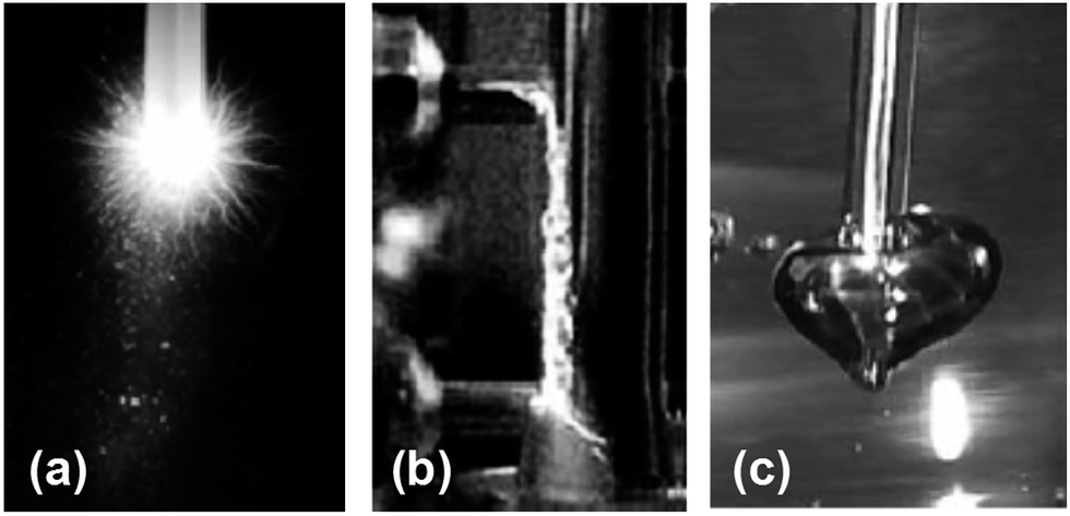 | ||
| Fig. 19 Method of generating in-liquid plasma for use in water treatment: (a) method of the immersed electrodes in water; (b) method using water flow; (c) method using bubbles. Reproduced from Akiyama et al.220 Copyright 2014 by The Japan Society of Plasma Science and Nuclear Fusion Research. | ||
Various oxidative active species are used in water treatments. Among these, the most powerful oxidative species are the ˙OH radicals. Accordingly, studies have been carried out to increase the concentration of ˙OH radicals and enhance diffusion efficiency in water in those water treatment processes that involve in-liquid plasma.222 In addition, generation of ˙OH radicals by in-liquid plasma in water and the decomposition of contaminants have also been undertaken.223 The mechanism of ˙OH radical generation by in-liquid plasma is summarized by eqn (3)–(6). Electrons (e−*) generated by the in-liquid plasma dissociate water and lead to the formation of ˙OH radicals (eqn (3)). On the other hand, interaction of these electrons (e−*; eqn (4)) with dissolved oxygen generates oxygen atoms in their excited O(1D) and ground O(3P) states, which ultimately generate ˙OH radicals from water (eqn (5) and (6)).223 Therefore, increasing the concentration of dissolved oxygen leads to an increase in the concentration of ˙OH species. However, as the concentration of ˙OH radicals increases, their subsequent recombination may be facilitated, so that it is disadvantageous to produce too many such species; note that the recombination process depends on the diffusion conditions of the ˙OH radical species.
| e−* + H2O → e− + ˙OH + H˙ | (3) |
| e−* + O2 → e− + O(1D) + O(3P) | (4) |
| O(1D) + H2O → 2OH˙ | (5) |
| O(3P) + H2O → 2OH˙ | (6) |
Horikoshi et al.156 achieved successful decomposition of perfluorooctanoic acid (PFOA) in ion-exchange water using in-liquid plasma. The methodology involved concurrent ultrasonic/microwave irradiation in an in-liquid plasma type generator; results are reported in Fig. 20.
 | ||
| Fig. 20 Defluorination yields (%) from the degradation of aqueous PFOA solutions (0.01 mM) by ultrasonic cavitation alone and by the microwave discharge in-liquid plasma method under simultaneous ultrasonic cavitation (MW power, 220 W; power for cavitation, 90 W). Reproduced from Horikoshi et al.156 Copyright 2017 by Elsevier. | ||
Plasma irradiation of PFOA (0.01 mM) in aqueous media for 90 s led to 59% defluorination accompanying the decomposition of PFOA, a substrate noted above as being difficult to decompose even with ˙OH radicals. Nonetheless, PFOA was decomposed synergistically by the cavitation effect generated by the homogenizer in addition to the local heat and shock waves generated by the in-liquid plasma. Monitoring the decomposition of PFOA by liquid chromatography/mass spectrometry (LC-MS) revealed a peak for PFOA at m/z = 413 that decreased in intensity (thus, decomposition of PFOA) and formation of intermediates whose peak intensities at m/z = 363, 313, 263 increased. Assigning these peaks to the various intermediates revealed that the decomposition of PFOA progressed through a gradual release of –CF2– units (Scheme 1). Complete mineralization of PFOA to CO2 gas and F− ions was achieved.156
 | ||
| Scheme 1 Sequential loss of CF2 units from the PFOA perfluorinated acid and decarboxylated intermediates produced during the degradation of PFOA by plasma irradiation for 90 s. Note that loss of CF2 units after the first decarboxylation step likely occurs by oxidation of the protonated terminal carbon and formation of F− ions and CO2 and so on in the Z-type pathway shown above. From Horikoshi and coworkers.156 Copyright 2017 by Elsevier. | ||
 | ||
| Fig. 21 Decomposition of methylene blue in aqueous solution by in-liquid plasma alone and in combination with photocatalyst TiO2 particles.17 Copyright 2017 by S. Horikoshi. | ||
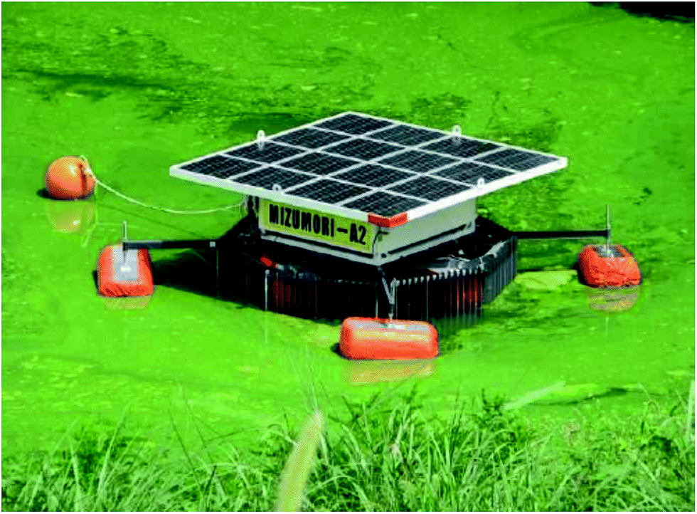 | ||
| Fig. 22 Photograph of a self-propelled in-liquid plasma apparatus floating over a dam to destroy the harmful Microcystis aeruginosa. Reproduced from ref. 251. Copyright Kumamoto University, Japan. | ||
A large-sized apparatus that can process industrial wastewaters at low cost and re-use of the recycled water is being considered by the Mitsubishi Electric Co. Japan.252 Unlike existing equipment, the particular equipment being considered features wastewater treatment that can be carried out with a simple method with no chemicals involved. As such, it is characterized by low cost and no concerns with regard to secondary pollution and use of the recycled waters. This equipment is expected to become an integral part of a manufacturing process.
4. Summary remarks
This review article has outlined and described in-liquid plasma and has provided application examples of nanomaterials synthesis and wastewater treatment. Related to the present discussion, an earlier article by Kareem and Kaliani253 reviewed the glow discharge plasma electrolytic technique for nanoparticles synthesis, while Chen et al.254 provided a theoretical analysis of the nanomaterial synthetic process from a physics point of view, and most recently Rumbach and Go255 provided a perspectives article on plasmas. It is clear from the literature that compared to gas and solid plasmas the in-liquid plasma technique has yet to fully mature from a physical and engineering viewpoints. In addition, because it has yet to be fully developed exploitation of in-liquid plasma toward new chemical processes is highly desirable without being bound to some fixed concept of the past. Accordingly, in-liquid plasma is a field filled with many possibilities and consequently should trigger the discovery of innovative processes and products.Conflicts of interest
Authors declare no conflicts of interest.Acknowledgements
This article would not have been possible without the fruitful collaboration of many University and industrial collaborators, and not least without the cooperation of many students whose names appear in many of the earlier publications; we are indeed grateful to them. We also wish to thank Dr S. Sato of the Saitama Institute of Technology (Japan) for the opportunity to further our interest in and appreciation of in-liquid plasma. We are also grateful to the Japan Society for the Promotion of Science (JSPS) for financial support to SH through a Grant-in-aid for Scientific Research (No. C-25420820). Financial support from the Sophia University-wide Collaborative Research Fund to SH is also appreciated. One of us (NS) thanks Professor Angelo Albini of the University of Pavia (Italy) for his continued hospitality during the many winter semesters in his PhotoGreen Laboratory.Notes and references
- S. Horikoshi, R. F. Schiffmann, J. Fukushima and N. Serpone, Microwave Chemical and Materials Processing: A Tutorial, Springer, Japan, 2017, in press Search PubMed.
- I. Rahim, S. Nomura, S. Mukasa and H. Toyota, Decomposition of methane hydrate for hydrogen production using microwave and radio frequency in-liquid plasma methods, Appl. Therm. Eng., 2015, 90, 120–126 CrossRef CAS.
- A. Piel, Plasma Physics: An Introduction to Laboratory, Space, and Fusion Plasmas, Springer-Verlag, Berlin Heidelberg, 2010 Search PubMed.
- W. Crookes, On a fourth state of matter, Proc. R. Soc. London, 1879, 30, 469–472 CrossRef.
- J. J. Thomson, Cathode rays, London Edinburgh Dublin, Philos. Mag., 1897, 44, 293–316 CrossRef.
- I. Langmuir, Oscillations in ionized gases, Proc. Natl. Acad. Sci. U. S. A., 1928, 14, 627–637 CrossRef CAS.
- R. Itatani, Progress of plasma physics in 20th century and future, Appl. Phys. Express, 2000, 69, 971–977 CAS.
- M. Laroussi, Sterilization of contaminated matter with an atmospheric pressure plasma, IEEE Trans. Plasma Sci., 1996, 24, 1188–1191 CrossRef CAS.
- R. J. Goldston and P. H. Rutherford, Introduction to plasma physics, Taylor & Francis, New York, 1995, ch. 1 Search PubMed.
- See: https://ia902704.us.archive.org/31/items/onradiantmatterl00croorich/onradiantmatterl00croorih.pdf, accessed August 2017.
- S. Horikoshi and N. Serpone, Microwaves in Nanoparticle Synthesis – Fundamentals and Applications, ed. S. Horikoshi and N. Serpone, Wiley-VCH, Weinheim, Germany, 2013, ch. 1 Search PubMed.
- J. S. Clements, M. Sato and R. H. Davis, Preliminary investigation of pre-breakdown phenomena and chemical reactions using a pulsed high-voltage discharge in water, IEEE Trans. Ind. Appl., 1987, IA-23, 224–235 CrossRef CAS.
- J. C. Devins, S. J. Rzad and R. J. Schwabe, Breakdown and pre-breakdown phenomena in liquids, J. Appl. Phys., 1981, 52, 4531–4545 CrossRef CAS.
- K. Yasukoka, T. Haehara, J. Katsuki, S. Katsuki, T. Namihira, T. Kaneko and R. Hatakeyama, Generation of underwater discharge plasma and its property, J. Plasma Fusion Res., 2008, 84, 666–673 Search PubMed.
- K. Schoenbach, J. Kolb, S. Xiao, S. Katsuki, Y. Minamitani and R. Joshi, Electrical breakdown of water in microgaps, Plasma Sources Sci. Technol., 2008, 17, 024010 CrossRef.
- T. Namihira, S. Sakai, T. Yamaguchi, K. Yamamoto, C. Yamada, T. Kiyan, T. Sakugawa and S. Katsuki, Electron temperature and electron density of underwater pulsed discharge plasma produced by solid-state pulsed-power generator, IEEE Trans. Plasma Sci., 2007, 35, 614–618 CrossRef.
- S. Horikoshi et al., to be submitted for publication in 2017.
- G. Harrison, Wavelength tables: Wavelength by Element, MIT Press, 1982, vol. 2 Search PubMed.
- D. Mariotti, J. Patel, V. Švrček and P. Maguire, Plasma–liquid interactions at atmospheric pressure for nanomaterials synthesis and surface engineering, Plasma Processes Polym., 2012, 9, 1074–1085 CrossRef CAS.
- A. Hickling and M. D. Ingram, Contact glow-discharge electrolysis, Trans. Faraday Soc., 1964, 60, 783–793 RSC.
- T. Tsuji, T. Mizuki, S. Ozono and M. Tsuji, Laser-induced silver nanocrystal formation in polyvinylpyrrolidone solutions, J. Photochem. Photobiol., A, 2009, 206, 134–139 CrossRef CAS.
- I. B. Gornushkin and U. Panne, Radiative models of laser-induced plasma and pump-probe diagnostics relevant to laser-induced breakdown spectroscopy, Spectrochim. Acta, Part B, 2000, 65, 345–359 CrossRef.
- G. Saito and T. Akiyama, Nanomaterial synthesis using plasma generation in liquid, J. Nanomater., 2015, 2015, 1–21 CrossRef.
- Y.-B. Xie and C.-J. Liu, Stability of ionic liquids under the influence of glow discharge plasmas, Plasma Processes Polym., 2008, 5, 239–245 CrossRef CAS.
- Z. Wei and C.-J. Liu, Synthesis of monodisperse gold nanoparticles in ionic liquid by applying room temperature plasma, Mater. Lett., 2011, 65, 353–355 CrossRef CAS.
- Y. Xie, Z. Wei, C.-J. Liu, L. Cui and C. Wang, Morphologic evolution of Au nanocrystals grown in ionic liquid by plasma reduction, J. Colloid Interface Sci., 2012, 374, 40–44 CrossRef CAS PubMed.
- Z. Wang, C.-J. Liu and G. Zhang, Size control of carbon black supported platinum nanoparticles via novel plasma reduction, Catal. Commun., 2009, 10, 959–962 CrossRef CAS.
- X. Liang, Z.-J. Wang and C.-J. Liu, Size-controlled synthesis of colloidal gold nanoparticles at room temperature under the influence of glow discharge, Nanoscale Res. Lett., 2010, 5, 124–129 CrossRef CAS PubMed.
- R. Molina, C. Ligero, P. Jovančić and E. Bertran, In situ polymerization of aqueous solutions of NIPAAm initiated by atmospheric plasma treatment, Plasma Processes Polym., 2013, 10, 506–516 CrossRef CAS.
- A. Ananth and Y. S. Mok, “Synthesis of RuO2 nanomaterials under dielectric barrier discharge plasma at atmospheric pressure – influence of substrates on the morphology and application, Chem. Eng. J., 2014, 239, 290–298 CrossRef CAS.
- K. Kitano, H. Aoki and S. Hamaguchi, Radio-frequency driven atmospheric-pressure plasmas in contact with liquid water, Jpn. J. Appl. Phys., Part 1, 2006, 45, 8294–8297 CrossRef CAS.
- E. Acayanka, A. T. Djowe, S. Laminsi, C. C. Tchoumkwé, S. Nzali, A. P. Mbouopda, P. T. Ndifon and E. M. Gaigneaux, Plasma-assisted synthesis of TiO2 nanorods by gliding arc discharge processing at atmospheric pressure for photocatalytic applications, Plasma Chem. Plasma Process., 2013, 33, 725–735 CrossRef CAS.
- T. Kaneko, K. Baba, T. Harada and R. Hatakeyama, Novel gas-liquid interfacial plasmas for synthesis of metal nanoparticles, Plasma Processes Polym., 2009, 6, 713–718 CrossRef CAS.
- T. Kaneko, K. Baba and R. Hatakeyama, Static gas-liquid interfacial direct current discharge plasmas using ionic liquid cathode, J. Appl. Phys., 2009, 105, 103306 CrossRef.
- K. Baba, T. Kaneko and R. Hatakeyama, Efficient synthesis of gold nanoparticles using ion irradiation in gas-liquid interfacial plasmas, Appl. Phys. Express, 2009, 2, 035006 CrossRef.
- K. Baba, T. Kaneko, R. Hatakeyama, K. Motomiya and K. Tohji, Synthesis of monodispersed nanoparticles functionalized carbon nanotubes in plasma-ionic liquid interfacial fields, Chem. Commun., 2010, 46, 255–257 RSC.
- T. Kaneko, Q. Chen, T. Harada and R. Hatakeyama, Structural and reactive kinetics in gas-liquid interfacial plasmas, Plasma Sources Sci. Technol., 2011, 20, 034014 CrossRef.
- Q. Chen, T. Kaneko and R. Hatakeyama, Rapid synthesis of water-soluble gold nanoparticles with control of size and assembly using gas-liquid interfacial discharge plasma, Chem. Phys. Lett., 2012, 521, 113–117 CrossRef CAS.
- Q. Chen, T. Kaneko and R. Hatakeyama, Characterization of pulse-driven gas-liquid interfacial discharge plasmas and application to synthesis of gold nanoparticle-DNA encapsulated carbon nanotubes, Curr. Appl. Phys., 2011, 11, S63–S66 CrossRef.
- S. A. Meiss, M. Rohnke, L. K. P. Doz, S. Z. E. Abedin, F. Endres and J. Janek, Employing plasmas as gaseous electrodes at the free surface of ionic liquids: deposition of nanocrystalline silver particles, ChemPhysChem, 2007, 8, 50–53 CrossRef CAS PubMed.
- M. Brettholle, O. Höfft, L. Klarhöfer, S. Mathes, W. Maus-Friedrichs, S. Z. E. Abedin, S. Krischok, J. Janekd and F. Endres, Plasma electrochemistry in ionic liquids: deposition of copper nanoparticles, Phys. Chem. Chem. Phys., 2010, 12, 1750–1755 RSC.
- O. Höfft and F. Endres, Plasma electrochemistry in ionic liquids: an alternative route to generate nanoparticles, Phys. Chem. Chem. Phys., 2011, 13, 13472 RSC.
- N. Kulbe, O. Höfft, A. Ulbrich, S. Z. E. Abedin, S. Krischok, J. Janekd, M. Pölleth and F. Endres, Plasma electrochemistry in 1-butyl-3-methyl-imidazolium dicyanamide: copper nano-particles from CuCl and CuCl2, Plasma Processes Polym., 2011, 8, 32–37 CrossRef CAS.
- F. Yang, Y. Li, T. Liu, K. Xu, L. Zhang, C. Xu and J. Gao, Plasma synthesis of Pd nanoparticles decorated-carbon nanotubes and its application in Suzuki reaction, Chem. Eng. J., 2013, 226, 52–58 CrossRef CAS.
- T. Liu, F. Yang, Y. Li, L. Ren, L. Zhang, K. Xu, X. Wang, C. Xu and J. Gao, Plasma synthesis of carbon nanotube-gold nanohybrids: efficient catalysts for green oxidation of silanes in water, J. Mater. Chem., 2014, 2, 245–250 RSC.
- C. Sugama, F. Tochikubo and S. Uchida, Glow discharge formation over water surface at saturated water vapor pressure and its application to wastewater treatment, Jpn. J. Appl. Phys., Part 1, 2006, 45, 8858–8863 CrossRef CAS.
- A. Hickling and M. D. Ingram, Glow-discharge electrolysis, J. Electroanal. Chem., 1964, 8, 65–81 CAS.
- H. Kawamura, K. Moritani and Y. lto, Discharge electrolysis in molten chloride: formation of fine silver particles, Plasmas Ions, 1998, 1, 29–36 CrossRef CAS.
- M. Tokushige, T. Nishikiori and Y. Ito, Plasma-induced cathodic discharge electrolysis to form various metal/alloy nanoparticles, Russ. J. Electrochem., 2010, 46, 619–626 CrossRef CAS.
- M. Tokushige, H. Tsujimura, T. Nishikiori and Y. Ito, Formation of metallic Si and SiC nanoparticles from SiO2 particles by plasma-induced cathodic discharge electrolysis in chloride melt, Electrochim. Acta, 2013, 100, 300–303 CrossRef CAS.
- M. Tokushige, T. Yamanaka, A. Matsuura, T. Nishikiori and Y. Ito, Synthesis of magnetic nanoparticles (Fe and FePt) by plasma-induced cathodic discharge electrolysis, IEEE Trans. Plasma Sci., 2009, 37, 1156–1160 CrossRef CAS.
- M. Tokushige, T. Nishikiori and Y. Ito, Formation of fine Ni nanoparticle by plasma-induced cathodic discharge electrolysis using rotating disk anode, J. Electrochem. Soc., 2010, 157, E162–E166 CrossRef CAS.
- M. Tokushige, T. Nishikiori and Y. Ito, Synthesis of Ni nanoparticles by plasma-induced cathodic discharge electrolysis, J. Appl. Electrochem., 2009, 39, 1665–1670 CrossRef CAS.
- M. Tokushige, H. Hongo, T. Nishikiori and Y. Ito, Formation of Sm-Co intermetallic compound nanoparticles based on plasma-induced cathodic discharge electrolysis in chloride melt, J. Electrochem. Soc., 2012, 159, E5–E10 CrossRef CAS.
- M. Tokushige, T. Nishikiori, M. C. Lafouresse, C. Michiokad, K. Yoshimurad, Y. Fukunakac and Y. Ito, Formation of FePt intermetallic compound nanoparticles by plasma induced cathodic discharge electrolysis, Electrochim. Acta, 2010, 55, 8154–8159 CrossRef CAS.
- P. Bruggeman, E. Ribězl, J. Degroote, J. Vierendeels and C. Leys, Plasma characteristics and electrical breakdown between metal and water electrodes, J. Optoelectron. Adv. Mater., 2008, 10, 1964–1967 CAS.
- W.-T. Yao, S.-H. Yu, Y. Zhou, J. Jiang, Q.-S. Wu, L. Zhang and J. Jiang, Formation of uniform CuO nanorods by spontaneous aggregation: selective synthesis of CuO, Cu2O, and Cu nanoparticles by a solid-liquid phase arc discharge process, J. Phys. Chem. B, 2005, 109, 14011–14016 CrossRef CAS PubMed.
- K. Furuya, Y. Hirowatari, T. Ishioka and A. Harata, Protective agent-free preparation of gold nanoplates and nanorods in aqueous HAuCl4 solutions using gas-liquid interface discharge, Chem. Lett., 2007, 36, 1088–1089 CrossRef CAS.
- M. Ito, M. Hayakawa, S. Takashima, E. Asami, T. Aoki, M. Oka, H. Asano, M. Kitahara, S. Nakata and K. Yamaguchi, Preparation of aqueous dispersion of titanium dioxide nanoparticles using plasma on liquid surface, Jpn. J. Appl. Phys., 2012, 51, 116201 CrossRef.
- T. Hagino, H. Kondo, K. Ishikawa, H. Kano, M. Sekine and M. Hori, Ultrahigh-speed synthesis of nanographene using alcohol in-liquid plasma, Appl. Phys. Express, 2012, 5, 035101 CrossRef.
- M. Matsushima, M. Noda, T. Yoshida, H. Kato, G. Kalita, T. Kizuki, H. Uchida, M. Umeno and K. Wakita, Formation of graphene nano-particle by means of pulsed discharge to ethanol, J. Appl. Phys., 2013, 113, 114304 CrossRef.
- D. Kozak, E. Shibata, A. Iizuka and T. Nakamura, Growth of carbon dendrites on cathode above liquid ethanol using surface plasma, Carbon, 2014, 70, 87–94 CrossRef CAS.
- M. Tokushige, A. Matsuura, T. Nishikiori and Y. Ito, Formation of Co-Pt intermetallic compound nanoparticles by plasma induced cathodic discharge electrolysis in a chloride melt, J. Electrochem. Soc., 2011, 158, E21–E26 CrossRef CAS.
- Y. Hayashi, S. Machmudah, N. Takada, H. Kanda, K. Sasaki and M. Goto, Decomposition of methyl orange using pulsed discharge plasma at atmospheric pressure: effect of different electrodes, Jpn. J. Appl. Phys., 2014, 53, 010212 CrossRef.
- I. G. Koo, M. S. Lee, J. H. Shim, J. H. Ahn and W. M. Lee, Platinum nanoparticles prepared by a plasma-chemical reduction method, J. Mater. Chem., 2005, 15, 4125–4128 RSC.
- C. Richmonds and R. M. Sankaran, Plasma-liquid electrochemistry: rapid synthesis of colloidal metal nanoparticles by microplasma reduction of aqueous cations, Appl. Phys. Lett., 2008, 93, 131501 CrossRef.
- N. Shirai, M. Nakazawa, S. Ibuka and S. Ishii, Atmospheric DC glow microplasmas using miniature gas flow and electrolyte cathode, Jpn. J. Appl. Phys., 2009, 48, 036002 CrossRef.
- F.-C. Chang, C. Richmonds and R. M. Sankaran, Microplasma-assisted growth of colloidal Ag nanoparticles for point of-use surface-enhanced Raman scattering applications, J. Vac. Sci. Technol., A, 2010, 28, L5 CAS.
- V. Svrcek, D. Mariotti and M. Kondo, Microplasma-induced surface engineering of silicon nanocrystals in colloidal dispersion, Appl. Phys. Lett., 2010, 97, 161502 CrossRef.
- W.-H. Chiang, C. Richmonds and R. M. Sankaran, Continuous-flow, atmospheric-pressure microplasmas: aversatile source for metal nanoparticle synthesis in the gas or liquid phase, Plasma Sources Sci. Technol., 2010, 19, 034011 CrossRef.
- X. Z. Huang, X. X. Zhong, Y. Lu, Y. Li, A. E. Rider, S. A. Furman and K. Ostrikov, Plasmonic Ag nanoparticles via environment-benign atmospheric microplasma electrochemistry, Nanotechnology, 2013, 24, 095604 CrossRef CAS PubMed.
- J. Patel, L. Němcová, P. Maguire, W. G. Graham and D. Mariotti, Synthesis of surfactant-free electrostatically stabilized gold nanoparticles by plasma-induced liquid chemistry, Nanotechnology, 2013, 24, 245604 CrossRef CAS PubMed.
- C. Du and M. Xiao, Cu2O nanoparticles synthesis by microplasma, Sci. Rep., 2014, 4, 7339–7344 CrossRef CAS PubMed.
- R. Wang, S. Zuo, D. Wu, J. Zhang, W. Zhu, K. H. Becker and J. Fang, Microplasma-assisted synthesis of colloidal gold nanoparticles and their use in the detection of cardiac troponin I (cTn-I), Plasma Processes Polym., 2015, 12, 380–391 CrossRef CAS.
- T. Yan, X. Zhong, A. E. Rider, Y. Lu, S. A. Furman and K. Ostrikov, Microplasma-chemical synthesis and tunable real time plasmonic responses of alloyed AuxAg1-x nanoparticles, Chem. Commun., 2014, 50, 3144–3147 RSC.
- N. Shirai, S. Uchida and F. Tochikubo, Synthesis of metal nanoparticles by dual plasma electrolysis using atmospheric dc glow discharge in contact with liquid, Jpn. J. Appl. Phys., 2014, 53, 046202 CrossRef.
- B. Sun, M. Sato and J. S. Clements, Optical study of active species produced by a pulsed streamer corona discharge in water, J. Electrost., 1997, 39, 189–202 CrossRef CAS.
- P. Bruggeman, T. Verreycken, M. Á. Gonález, J. L. Walsh, M. G. Kong, C. Leys and D. C. Schram, Optical emission spectroscopy as a diagnostic for plasmas in liquids: opportunities and pitfalls, J. Phys. D: Appl. Phys., 2010, 43, 124005 CrossRef.
- Q. Chen, T. Kitamura, K. Saito, K. Haruta, Y. Yamano, T. Ishikawa and H. Shirai, Microplasma discharge in ethanol solution: characterization and its application to the synthesis of carbon microstructures, Thin Solid Films, 2008, 516, 4435–4440 CrossRef CAS.
- K. Greda, P. Jamroz and P. Pohl, Effect of the addition of nonionic surfactants on the emission characteristic of direct current atmospheric pressure glow discharge generated in contact with a flowing liquid cathode, J. Anal. At. Spectrom., 2012, 28, 134–141 RSC.
- P. Jamroz, K. Greda and P. Pohl, Development of direct current, atmospheric-pressure, glow discharges generated in contact with flowing electrolyte solutions for elemental analysis by optical emission spectrometry, TrAC, Trends Anal. Chem., 2012, 41, 105–121 CrossRef CAS.
- P. Jamróz, P. Pohl and W. Zyrnicki, An analytical performance of atmospheric pressure glow discharge generated in contact with flowing small size liquid cathode, J. Anal. At. Spectrom., 2012, 27, 1032–1037 RSC.
- K. Greda, P. Jamroz and P. Pohl, Comparison of the performance of direct current atmospheric pressure glow microdischarges operated between a small sized flowing liquid cathode and miniature argon or helium flow microjets, J. Anal. At. Spectrom., 2013, 28, 1233–1241 RSC.
- K. Greda, P. Jamroz, A. Dzimitrowicz and P. Pohl, Direct elemental analysis of honeys by atmospheric pressure glow discharge generated in contact with a flowing liquid cathode, J. Anal. At. Spectrom., 2014, 30, 154–161 RSC.
- S. A. Campbell, V. J. Cunnane and D. J. Schiffrin, Cathodic contact glow discharge electrolysis under reduced pressure, J. Electroanal. Chem., 1992, 325, 257–268 CrossRef CAS.
- A. Lal, H. Bleuler and R. Wüthrich, Fabrication of metallic nanoparticles by electrochemical discharges, Electrochem. Commun., 2008, 10, 488–491 CrossRef CAS.
- Y. Zhou, S. H. Yu, X. P. Cui, G. Y. Wang and Z. Y. Chen, Formation of silver nanowires by a novel solid-liquid phase arc discharge method, Chem. Mater., 1999, 11, 545–546 CrossRef CAS.
- Y. Toriyabe, S. Watanabe, S. Yatsu, T. Shibayama and T. Mizuno, Controlled formation of metallic nanoballs during plasma electrolysis, Appl. Phys. Lett., 2007, 91, 041501 CrossRef.
- G. Saito, S. Hosokai, T. Akiyama, S. Yoshida, S. Yatsu and S. Watanabe, Size-controlled Ni nanoparticles formation by solution glow discharge, J. Phys. Soc. Jpn., 2010, 79, 083501 CrossRef.
- G. Saito, S. Hosokai and T. Akiyama, Synthesis of ZnO nanoflowers by solution plasma, Mater. Chem. Phys., 2011, 130, 79–83 CrossRef CAS.
- G. Saito, S. Hosokai, M. Tsubota and T. Akiyama, Nickel nanoparticles formation from solution plasma using edge shielded electrode, Plasma Chem. Plasma Process., 2011, 31, 719–728 CrossRef CAS.
- G. Saito, S. Hosokai, M. Tsubota and T. Akiyama, Synthesis of copper/copper oxide nanoparticles by solution plasma, J. Appl. Phys., 2011, 110, 023302 CrossRef.
- G. Saito, S. Hosokai, M. Tsubota and T. Akiyama, “Surface morphology of a glow discharge electrode in a solution, J. Appl. Phys., 2012, 112, 013306 CrossRef.
- G. Saito, S. Hosokai, M. Tsubota and T. Akiyama, Influence of solution temperature and surfactants on morphologies of tin oxide produced using a solution plasma technique, Cryst. Growth Des., 2012, 12, 2455–2459 CAS.
- Z. Wu, Z.-K. Zhang, D.-Z. Guo, Y.-J. Xing and G.-M. Zhang, Titanium oxide nanospheres: preparation, characterization, and wide-spectral absorption, Phys. Status Solidi A, 2012, 209, 2020–2026 CrossRef CAS.
- A. Allagui, E. A. Baranova and R. Wüthrich, Synthesis of Ni and Pt nanomaterials by cathodic contact glow discharge electrolysis in acidic and alkaline media, Electrochim. Acta, 2013, 93, 137–142 CrossRef CAS.
- Y. Nakasugi, G. Saito, T. Yamashita and T. Akiyama, Synthesis of nonstoichiometric titanium oxide nanoparticles using discharge in HCl solution, J. Appl. Phys., 2014, 115, 123303 Search PubMed.
- G. Saito, W. O. S. B. W. M. Azman, Y. Nakasugi and T. Akiyama, Optimization of electrolyte concentration and voltage for effective formation of Sn/SnO2 nanoparticles by electrolysis in liquid, Adv. Powder Technol., 2014, 25, 1038–1042 CrossRef CAS.
- G. Saito, Y. Nakasugi and T. Akiyama, Excitation temperature of a solution plasma during nanoparticle synthesis, J. Appl. Phys., 2014, 116, 083301 Search PubMed.
- G. Saito, Y. Nakasugi, T. Yamashita and T. Akiyama, Solution plasma synthesis of ZnO flowers and their photoluminescence properties, Appl. Surf. Sci., 2014, 290, 419–424 CrossRef CAS.
- G. Saito, C. Zhu and T. Akiyama, Surfactant-assisted synthesis of Sn nanoparticles via solution plasma technique, Adv. Powder Technol., 2014, 25, 728–732 CrossRef CAS.
- G. Saito, Y. Nakasugi, T. Yamashita and T. Akiyama, Solution plasma synthesis of bimetallic nanoparticles, Nanotechnology, 2014, 25, 135603 CrossRef PubMed.
- T. Paulmier, J. M. Bell and P. M. Fredericks, Development of a novel cathodic plasma/electrolytic deposition technique. Part 2: physicochemical analysis of the plasma discharge, Surf. Coat. Technol., 2007, 201, 8771–8781 CrossRef CAS.
- J. Gao, A. Wang, Y. Li, Y. Fu, J. Wu, Y. Wang and Y. Wang, Synthesis and characterization of superabsorbent composite by using glow discharge electrolysis plasma, React. Funct. Polym., 2008, 68, 1377–1383 CrossRef CAS.
- T. Paulmier, J. M. Bell and P. M. Fredericks, Plasma electrolytic deposition of titanium dioxide nanorods and nano-particles, J. Mater. Process. Technol., 2008, 208, 117–123 CrossRef CAS.
- G. Saito, S. Hosokai, M. Tsubota and T. Akiyama, Ripple formation on a nickel electrode during a glow discharge in a solution, Appl. Phys. Lett., 2012, 100, 181601 CrossRef.
- M. R. M. B. Julaihi, S. Yatsu, M. Jeem and S. Watanabe, Synthesis of stainless steel nanoballs via submerged glow-discharge plasma and its photocatalytic performance in methylene blue decomposition, J. Exp. Nanosci., 2014, 10, 965–982 CrossRef.
- G. Saito and N. Sakaguchi, Solution plasma synthesis of Si nanoparticles, Nanotechnology, 2015, 26, 235602 CrossRef PubMed.
- K. Azumi, A. Kanada, M. Kawaguchi and M. Seo, Formation of microparticles from titanium and silicon electrodes using high voltage discharge in electrolyte solution, Hyomen Jijutsu, 2005, 56, 938–941 CAS.
- L. Schaper, W. G. Graham and K. R. Stalder, Vapour layer formation by electrical discharges through electrically conducting liquids—modelling and experiment, Plasma Sources Sci. Technol., 2011, 20, 034003 CrossRef.
- L. Schaper, K. R. Stalder and W. G. Graham, Plasma production in electrically conducting liquids, Plasma Sources Sci. Technol., 2011, 20, 034004 CrossRef.
- P. Ruma, N. Lukes, N. Aoki, E. Spetlikova, S. H. R. Hosseini, T. Sakugawa and H. Akiyama, Effects of pulse frequency of input power on the physical and chemical properties of pulsed streamer discharge plasmas in water, J. Phys. D: Appl. Phys., 2013, 46, 125202 CrossRef.
- G. Saito, Y. Nakasugi and T. Akiyama, Generation of solution plasma over a large electrode surface area, J. Appl. Phys., 2015, 118, 023303 CrossRef.
- S. Yatsu, H. Takahashf, H. Sasaki, N. Sakaguchi, K. Ohkubo, T. Muramoto and S. Watanabe, Fabrication of nanoparticles by electric discharge plasma in liquid, Arch. Metall. Mater., 2013, 58, 425–429 CAS.
- G. Saito, Y. Nakasugi and T. Akiyama, High-speed camera observation of solution plasma during nanoparticles formation, Appl. Phys. Lett., 2014, 104, 83104 CrossRef.
- K. Kobayashi, Y. Tomita and M. Sanmyo, Electrochemical generation of hot plasma by pulsed discharge in an electrolyte, J. Phys. Chem. B, 2000, 104, 6318–6326 CrossRef CAS.
- T. Mizuno, T. Akimoto, K. Azumi, T. Ohmori, Y. Aoki and A. Takahashi, Hydrogen evolution by plasma electrolysis in aqueous solution, Jpn. J. Appl. Phys., Part 1, 2005, 44, 396–401 CrossRef CAS.
- A. Hickling and M. D. Ingram, Contact glow-discharge electrolysis, Trans. Faraday Soc., 1964, 60, 783–793 RSC.
- L. Wang, Aqueous organic dye discoloration induced by contact glow discharge electrolysis, J. Hazard. Mater., 2009, 171, 577–581 CrossRef CAS PubMed.
- Y. Liu and X. Jiang, Plasma-induced degradation of chlorobenzene in aqueous solution, Plasma Chem. Plasma Process., 2008, 28, 15–24 CrossRef CAS.
- K. Azumi, T. Mizuno, T. Akimoto and T. Ohmori, Light emission from Pt during high-voltage cathodic polarization, J. Electrochem. Soc., 1999, 146, 3374–3377 CrossRef CAS.
- S. K. Sengupta, R. Singh and A. K. Srivastava, A study on the origin of nonfaradaic behavior of anodic contact glow discharge electrolysis: the relationship between power dissipated in glow discharges and nonfaradaic yields, J. Electrochem. Soc., 1998, 145, 2209–2213 CrossRef CAS.
- J. Gong, J. Wang, W. Xie and W. Cai, Enhanced degradation of aqueous methyl orange by contact glow discharge electrolysis using Fe2+ as catalyst, J. Appl. Electrochem., 2008, 38, 1749–1755 CrossRef CAS.
- J. Gao, Z. Hu, X. Wang, J. Hou, X. Lu and J. Kang, Oxidative degradation of acridine orange induced by plasma with contact glow discharge electrolysis, Thin Solid Films, 2001, 390, 154–158 CrossRef CAS.
- J. Gao, X. Wang, Z. Hu, H. Deng, J. Hou, X. Lu and J. Kang, Plasma degradation of dyes in water with contact glow discharge electrolysis, Water Res., 2003, 37, 267–272 CrossRef CAS PubMed.
- J. Gao, Y. Liu, W. Yang, L. Pu, J. Yu and Q. Lu, Oxidative degradation of phenol in aqueous electrolyte induced by plasma from a direct glow discharge, Plasma Sources Sci. Technol., 2003, 12, 533–538 CrossRef CAS.
- P. Bruggeman, D. Schram, M. Á. González, R. Rego, M. G. Kong and C. Leys, Characterization of a direct dc-excited discharge in water by optical emission spectroscopy, Plasma Sources Sci. Technol., 2009, 18, 025017 CrossRef.
- K.-Y. Shih and B. R. Locke, Effects of electrode protrusion length, pre-existing bubbles, solution conductivity and temperature, on liquid phase pulsed electrical discharge, Plasma Processes Polym., 2009, 6, 729–740 CrossRef CAS.
- T. Maehara, K. Nishiyama, S. Onishi, S. Mukasa, H. Toyota, M. Kuramoto, S. Nomura and A. Kawashima, Degradation of methylene blue by radio frequency plasmas in water under ultraviolet irradiation, J. Hazard. Mater., 2010, 174, 473–476 CrossRef CAS PubMed.
- S. Mukasa, T. Maehara, S. Nomura, H. Toyota, A. Kawashima, Y. Hattori, Y. Hashimoto and H. Yamashita, Growth of bubbles containing plasma in water by high-frequency irradiation, Int. J. Heat Mass Transfer, 2010, 53, 3067–3074 CrossRef CAS.
- T. Maehara, S. Honda, C. Inokuchi, M. Kuramoto, S. Mukasa, H. Toyota, S. Nomura and A. Kawashima, Influence of conductivity on the generation of a radio frequency plasma surrounded by bubbles in water, Plasma Sources Sci. Technol., 2011, 20, 034016 CrossRef.
- T. Maehara, H. Toyota, M. Kuramoto, A. Iwamae, A. Tadokoro, S. Mukasa, H. I. Yamashita, A. Kawashima and S. Nomura, Radio frequency plasma in water, Jpn. J. Appl. Phys., Part 1, 2006, 45, 8864–8868 CrossRef CAS.
- T. Maehara, I. Miyamoto, K. Kurokawa, Y. Hashimoto, A. Iwamae, M. Kuramoto, H. Yamashita, S. Mukasa, H. Toyota, S. Nomura and A. Kawashima, Degradation of methylene blue by RF plasma in water, Plasma Chem. Plasma Process., 2008, 28, 467–482 CrossRef CAS.
- S. Nomura, H. Toyota, S. Mukasa, Y. Takahashi, T. Maehara, A. Kawashima and H. Yamashita, Discharge characteristics of microwave and high-frequency in-liquid plasma in water, Appl. Phys. Express, 2008, 1, 046002 CrossRef.
- S. Nomura, S. Mukasa, H. Toyota, H. Miyake, H. Yamashita, T. Maehara, A. Kawashima and F. Abe, Characteristics of in liquid plasma in water under higher pressure than atmospheric pressure, Plasma Sources Sci. Technol., 2011, 20, 034012 CrossRef.
- S. Mukasa, S. Nomura, H. Toyota, T. Maehara and H. Yamashita, Internal conditions of a bubble containing radiofrequency plasma in water, Plasma Sources Sci. Technol., 2011, 20, 034020 CrossRef.
- A. Kawashima, H. Toyota, S. Nomura, T. Takemori, S. Mukasa, T. Maehara and H. Yamashita, 27.12 MHz plasma generation in supercritical carbon dioxide, J. Appl. Phys., 2007, 101, 093303 CrossRef.
- T. Maehara, A. Kawashima, A. Iwamae, S. Mukasa, T. Takemori, T. Watanabe, K. Kurokawa, H. Toyota and S. Nomura, Spectroscopic measurements of high frequency plasma in supercritical carbon dioxide, Phys. Plasmas, 2009, 16, 033503 CrossRef.
- A. E. E. Putra, S. Nomura, S. Mukasa and H. Toyota, Hydrogen production by radio frequency plasma stimulation in methane hydrate at atmospheric pressure, Int. J. Hydrogen Energy, 2012, 37, 16000–16005 CrossRef CAS.
- Y. Hattori, S. Nomura, S. Mukasa, H. Toyota, T. Inoue and T. Usui, Synthesis of tungsten oxide, silver, and gold nanoparticles by radio frequency plasma in water, J. Alloys Compd., 2013, 578, 148–152 CrossRef CAS.
- S. Mukasa, S. Nomura and H. Toyota, Observation of microwave in-liquid plasma using high-speed camera, Jpn. J. Appl. Phys., Part 1, 2007, 46, 6015–6021 CrossRef CAS.
- S. Mukasa, S. Nomura, H. Toyota, T. Maehara, F. Abe and A. Kawashima, Temperature distributions of radio-frequency plasma in water by spectroscopic analysis, J. Appl. Phys., 2009, 106, 113302 CrossRef.
- Y. Hattori, S. Mukasa, S. Nomura and H. Toyota, Optimization and analysis of shape of coaxial electrode for microwave plasma in water, J. Appl. Phys., 2010, 107, 063305 CrossRef.
- Y. Hattori, S. Mukasa, H. Toyota, T. Inoue and S. Nomura, Synthesis of zinc and zinc oxide nanoparticles from zinc electrode using plasma in liquid, Mater. Lett., 2011, 65, 188–190 CrossRef CAS.
- Y. Hattori, S. Mukasa, H. Toyota, H. Yamashita and S. Nomura, Improvement in preventing metal contamination from an electrode used for generating microwave plasma in liquid, Surf. Coat. Technol., 2012, 206, 2140–2145 CrossRef CAS.
- Y. Hattori, S. Mukasa, H. Toyota and S. Nomura, Electrical breakdown of microwave plasma in water, Curr. Appl. Phys, 2013, 13, 1050–1054 CrossRef.
- Y. Hattori, S. Mukasa, H. Toyota, T. Inoue and S. Nomura, Continuous synthesis of magnesium- hydroxide, zinc-oxide, and silver nanoparticles by microwave plasma in water, Mater. Chem. Phys., 2011, 131, 425–430 CrossRef CAS.
- Y. Hattori, S. Nomura, S. Mukasa, H. Toyota, T. Inoue and T. Kasahara, Synthesis of tungsten trioxide nanoparticles by microwave plasma in liquid and analysis of physical properties, J. Alloys Compd., 2013, 560, 105–110 CrossRef CAS.
- H. Toyota, S. Nomura, S. Mukasa, H. Yamashita, T. Shimo and S. Okuda, A consideration of ternary C–H–O diagram for diamond deposition using microwave in-liquid and gas phase plasma, Diamond Relat. Mater., 2011, 20, 1255–1258 CrossRef CAS.
- T. Yonezawa, A. Hyono, S. Sato and O. Ariyada, Preparation of zinc oxide nanoparticles by using microwave-induced plasma in liquid, Chem. Lett., 2010, 39, 783–785 CrossRef CAS.
- S. Sato, K. Mori, O. Ariyada, H. Atsushi and T. Yonezawa, Synthesis of nanoparticles of silver and platinum by microwave induced plasma in liquid, Surf. Coat. Technol., 2011, 206, 955–958 CrossRef CAS.
- T. Ishijima, H. Hotta, H. Sugai and M. Sato, Multibubble plasma production and solvent decomposition in water by slot excited microwave discharge, Appl. Phys. Lett., 2007, 91, 121501 CrossRef.
- S. Nomura, A. E. E. Putra, S. Mukasa, H. Yamashita and H. Toyota, Plasma decomposition of clathrate hydrates by 2.45 GHz microwave irradiation at atmospheric pressure, Appl. Phys. Express, 2011, 4, 066201 CrossRef.
- H. Toyota, S. Nomura and S. Mukasa, A practical electrode for microwave plasma processes, Int. J. Mater. Sci. Appl., 2013, 2, 83–88 Search PubMed.
- T. Watano, K. Kurosawa and K. Mizuno, Effect of plasma-discharge in water on wire electrode, Aichi center, Indus. Sci. Technol., 2008 Search PubMed.
- S. Horikoshi, S. Sato, M. Abe and N. Serpone, A novel liquid plasma AOP device integrating microwaves and ultrasounds and its evaluation in defluorinating perfluorooctanoic acid in aqueous media, Ultrason. Sonochem., 2011, 18, 938–942 CrossRef CAS PubMed.
- X. Hua, X. Shen, O. Takai and N. Saito, Facile fabrication of PtAu alloy clusters using solution plasma sputtering and their electrocatalytic activity, J. Alloys Compd., 2013, 552, 351–355 CrossRef.
- See: http://www.chusho.meti.go.jp/keiei/sapoin/portal/seika/2010/22131318032.pdf, accessed August 2017.
- F. Xu, Y. Lu, Y. Xie and Y. Liu, Controllable morphology evolution of electrodeposited ZnO nano-/micro-scale structures in aqueous solution, Mater. Des., 2009, 30, 1704–1711 CrossRef CAS.
- S. Cho, S.-H. Jung and K.-H. Lee, Morphology-Controlled Growth of ZnO Nanostructures Using Microwave Irradiation: from Basic to Complex Structures, J. Phys. Chem. C, 2008, 112, 12769–12776 CAS.
- M. A. Bratescu, O. Takai and N. Saito, One-step synthesis of gold bimetallic nanoparticles with various metal-compositions, J. Alloys Compd., 2013, 562, 74–83 CrossRef CAS.
- H. Toyota, S. Nomura, Y. Takahashi and S. Mukasa, Submerged synthesis of diamond in liquid alcohol plasma, Diamond Relat. Mater., 2008, 17, 1902–1904 CrossRef CAS.
- G. Panomsuwan, N. Saito and T. Ishizaki, Electrocatalytic oxygen reduction on nitrogen-doped carbon nanoparticles derived from cyano-aromatic molecules via a solution plasma approach, Carbon, 2016, 98, 411–420 CrossRef CAS.
- T. Morishita, T. Ueno, G. Panomsuwan, J. Hieda, A. Yoshida, M. A. Bratescu and N. Saito, Fastest Formation Routes of Nanocarbons in Solution Plasma Processes, Sci. Rep., 2016, 6, 36880, DOI:10.1038/srep36880.
- A. Watthanaphanit, G. Panomsuwan and N. Saito, A novel one-step synthesis of gold nanoparticles in an alginate gel matrix by solution plasma sputtering, RSC Adv., 2014, 4, 1622–1629 RSC.
- X. L. Hu, O. Takai and N. Saito, Synthesis of gold nanoparticles by solution plasma sputtering in various solvents, J. Phys.: Conf. Ser., 2013, 417, 012030 CrossRef.
- C. Tsukada, T. Mizutani, S. Ogawa, T. Nomoto, Y. Abe, H. Nameki, K. Matsuo, G. Kutluk and S. Yagi, Adsorption reaction of L-cysteine on Au nanoparticle prepared by solution plasma, e-J. Surf. Sci. Nanotechnol., 2013, 11, 18–24 CrossRef CAS.
- T. Mizutani, T. Murai, H. Nameki, T. Yoshida and S. Yagi, In situ ultraviolet-visible absorbance measurement during and after solution plasma sputtering for preparation of colloidal gold nanoparticles, Jpn. J. Appl. Phys., 2014, 53, 11RA03 CrossRef.
- J.-K. Lung, J.-C. Huang, D.-C. Tien, C.-Y. Liao, K.-H. Tseng, T.-T. Tsung, W.-S. Kao, T.-H. Tsai, C.-S. Jwo, H.-M. Lin and L. Stobinskif, Preparation of gold nanoparticles by arc discharge in water, J. Alloys Compd., 2007, 434–435, 655–658 CrossRef CAS.
- S. M. Kim, G. S. Kim and S. Y. Lee, Effects of PVP and KCl concentrations on the synthesis of gold nanoparticles using a solution plasma processing, Mater. Lett., 2008, 62, 4354–4356 CrossRef CAS.
- Y. K. Heo, M. A. Bratescu, T. Ueno and N. Saito, Synthesis of mono-dispersed nanofluids using solution plasma, J. Appl. Phys., 2014, 116, 024302 CrossRef PubMed.
- S.-P. Cho, M. A. Bratescu, N. Saito and O. Takai, Microstructural characterization of gold nanoparticles synthesized by solution plasma processing, Nanotechnology, 2011, 22, 455701 CrossRef PubMed.
- X. Hu, S.-P. Cho, O. Takai and N. Saito, Rapid synthesis and structural characterization of well-defined gold clusters by solution plasma sputtering, Cryst. Growth Des., 2012, 12, 119–123 CAS.
- Y. K. Heo and S. Y. Lee, Effects of the gap distance on the characteristics of gold nanoparticles in nanofluids synthesized using solution plasma processing, Met. Mater. Int., 2011, 17, 431–434 CrossRef CAS.
- N. Saito, J. Hieda and O. Takai, Synthesis process of gold nanoparticles in solution plasma, Thin Solid Films, 2009, 518, 912–917 CrossRef CAS.
- O. Takai, Solution plasma processing (SPP), Pure Appl. Chem., 2008, 80, 2003–2011 CrossRef CAS.
- J. Hieda, N. Saito and O. Takai, Exotic shapes of gold nanoparticles synthesized using plasma in aqueous solution, J. Vac. Sci. Technol., A, 2008, 26, 854–856 CAS.
- J. Hieda, N. Saito and O. Takai, Size-regulated gold nanoparticles fabricated by a discharge in reverse micelle solutions, Surf. Coat. Technol., 2008, 202, 5343–5346 CrossRef CAS.
- A. A. Ashkarran, A. Iraji zad, S. M. Mahdavi, M. M. Ahadian and M. R. Hormozi nezhad, Rapid and efficient synthesis of colloidal gold nanoparticles by arc discharge method, Appl. Phys. A, 2009, 96, 423–428 CrossRef CAS.
- A. A. Ashkarran, A. Zad, M. M. Ahadian and M. R. Hormozi-Nezhad, Stability, size and optical properties of colloidal silver nanoparticles prepared by electrical arc discharge in water, Eur. Phys. J.: Appl. Phys., 2009, 48, 10601 CrossRef.
- C.-H. Lo, T.-T. Tsung and H.-M. Lin, Preparation of silver nanofluid by the submerged arc nanoparticle synthesis system (SANSS), J. Alloys Compd., 2007, 434–435, 659–662 CrossRef CAS.
- D.-C. Tien, K.-H. Tseng, C.-Y. Liao and T.-T. Tsung, Identification and quantification of ionic silver from colloidal silver prepared by electric spark discharge system and its antimicrobial potency study, J. Alloys Compd., 2009, 473, 298–302 CrossRef CAS.
- C. Cho, Y. W. Choi, C. Kang and G. W. Lee, Effects of the medium on synthesis of nanopowders by wire explosion process, Appl. Phys. Lett., 2007, 91, 141501 CrossRef.
- H. Lee, S. H. Park, S.-C. Jung, J.-J. Yun, S.-J. Kim and D.-H. Kim, Preparation of nonaggregated silver nanoparticles by the liquid phase plasma reduction method, J. Mater. Res., 2013, 28, 1105–1110 CrossRef CAS.
- A. A. Ashkarran, A novel method for synthesis of colloidal silver nanoparticles by arc discharge in liquid, Curr. Appl. Phys, 2010, 10, 1442–1447 CrossRef.
- B. G. Rodriguez-Méndez, R. López-Callejas, M. T. Olguin, R. Valencia-Alvarado, A. Mercado-Cabrera, R. Peña-Eguiluz and A. E. Muñoz-Castro, Growth of Ag particles from Ag-zeolite by pulsed discharges in water and their antibacterial activity, Microporous Mesoporous Mater., 2017, 244, 235–243 CrossRef.
- X. Hu, O. Takai and N. Saito, Simple synthesis of platinum nanoparticles by plasma sputtering in water, Jpn. J. Appl. Phys., 2013, 52, 01AN05 CrossRef.
- S.-Y. Xie, Z.-J. Ma, C.-F. Wang, S.-C. Lin, Z.-Y. Jiang, R.-B. Huang and L.-S. Zheng, Preparation and selfassembly of copper nanoparticles via discharge of copper rod electrodes in a surfactant solution: a combination of physical and chemical processes, J. Solid State Chem., 2004, 177, 3743–3747 CrossRef CAS.
- P. Pootawang, N. Saito and S. Y. Lee, Discharge time dependence of a solution plasma process for colloidal copper nanoparticle synthesis and particle characteristics, Nanotechnology, 2013, 24, 055604 CrossRef PubMed.
- V. S. Burakov, N. A. Savastenko, N. V. Tarasenko and E. A. Nevar, Synthesis of nanoparticles using a pulsed electrical discharge in a liquid, J. Appl. Spectrosc., 2008, 75, 114–124 CrossRef CAS.
- P. Pootawang, N. Saito, O. Takai and S.-Y. Lee, Synthesis and characteristics of Ag/Pt bimetallic nanocomposites by arc discharge solution plasma processing, Nanotechnology, 2012, 23, 395602 CrossRef PubMed.
- S. H. Sun and S.-C. Jung, Facile synthesis of bimetallic Ni-Cu nanoparticles using liquid phase plasma method, Korean J. Chem. Eng., 2016, 33, 1075–1079 CrossRef CAS.
- D. G. Tong, W. Chu, P. Wu and L. Zhang, Honeycomblike Co-B amorphous alloy catalysts assembled by a solution plasma process show enhanced catalytic hydrolysis activity for hydrogen generation, RSC Adv., 2012, 2, 2369–2376 RSC.
- N. Sano, H. Wang, M. Chhowalla, I. Alexandrou, G. A. J. Amaratunga, M. Naito and T. Kanki, Fabrication of inorganic molybdenum disulfide fullerenes by arc in water, Chem. Phys. Lett., 2003, 368, 331–337 CrossRef CAS.
- D. Delaportas, P. Svarnas, I. Alexandrou, A. Siokou, K. Black and J. W. Bradley, γ-Al2O3 nanoparticle production by arc-discharge in water: in situ discharge characterization and nanoparticle investigation, J. Phys. D: Appl. Phys., 2009, 42, 245204 CrossRef.
- M. Farajimotlagh, R. Poursalehi and M. Aliofkhazraei, Synthesis mechanisms, optical and structural properties of η-Al2O3 based nanoparticles prepared by DC arc discharge in environmentally friendly liquids, Ceram. Int., 2017, 43, 7717–7723 CrossRef CAS.
- A. A. Ashkarran, M. Kavianipour, S. M. Aghigh, S. A. A. Afshar, S. Saviz and A. I. Zad, On the formation of TiO2 nanoparticles via submerged arc discharge technique: synthesis, characterization and photocatalytic properties, J. Cluster Sci., 2010, 21, 753–766 CrossRef CAS.
- T. Jedsukontorn, T. Ueno, N. Saito and M. Hunsom, Facile preparation of defective black TiO2 through the solution plasma process: effect of parametric changes for plasma discharge on its structural and optical properties, J. Alloys Compd., 2017, 726, 567–577 CrossRef CAS.
- N. Su, X. Hu, J. Zhang, H. Huang, J. Cheng, J. Yu and C. Ge, Plasma-induced synthesis of Pt nanoparticles supported on TiO2 nanotubes for enhanced methanol electro-oxidation, Appl. Surf. Sci., 2017, 399, 403–410 CrossRef CAS.
- N. Janpetcha, N. Saitob and R. Rujiravanita, Fabrication of bacterial cellulose-ZnO composite via solution plasma process for antibacterial applications, Carbohydr. Polym., 2016, 148, 335–344 CrossRef PubMed.
- T. Velusamy, A. Liguori, M. Macias-Montero, D. B. Padmanaban, D. Carolan, M. Gherardi, V. Colombo, P. Maguire, V. Svrcek and D. Mariotti, Ultra-small CuO nanoparticles with tailored energy-band diagram synthesized by a hybrid plasma-liquid process, Plasma Processes Polym., 2017, 14, e1600224 CrossRef.
- J. Liu, B. He, Q. Chen, H. Liu, J. Li, Q. Xiong, X. Zhang, S. Yang, G. Yue and Q. H. Liu, Plasma electrochemical synthesis of cuprous oxide nanoparticles and their visible-light photocatalytic effect, Electrochim. Acta, 2016, 222, 1677–1681 CrossRef CAS.
- T. H. Kim, N. S. A. Eom, S.-O. Kang and Y.-H. Choa, Plasma-assisted electrolytic synthesis of In(OH)3 nanocubes for thermal transformation into In2O3 nanocubes with a controllable Sn content, RSC Adv., 2016, 6, 20337–20342 RSC.
- M. T. Beck, Z. Dinya, S. Kéki and L. Papp, Formation of C60 and polycyclic aromatic hydrocarbons upon electric discharges in liquid toluene, Tetrahedron, 1993, 49, 285–290 CrossRef CAS.
- V. Scuderi, C. Bongiorno, G. Faraci and S. Scalese, Effect of the liquid environment on the formation of carbon nanotubes and graphene layers by arcing processes, Carbon, 2012, 50, 2365–2369 CrossRef CAS.
- Y. L. Hsin, K. C. Hwang, F.-R. Chen and J.-J. Kai, Production and in-situ metal filling of carbon nanotubes in water, Adv. Mater., 2001, 13, 830–833 CrossRef CAS.
- N. Sano, M. Naito, M. Chhowalla, T. Kikuchi, S. Matsuda, K. Iimura, H. Wang, T. Kanki and G. A. J. Amaratunga, Pressure effects on nanotubes formation using the submerged arc in water method, Chem. Phys. Lett., 2003, 378, 29–34 CrossRef CAS.
- H. W. Zhu, X. S. Li, B. Jiang, C. L. Xu, Y. F. Zhu, D. H. Wu and X. H. Chen, Formation of carbon nanotubes in water by the electric-arc technique, Chem. Phys. Lett., 2002, 366, 664–669 CrossRef CAS.
- M. V. Antisari, R. Marazzi and R. Krsmanovic, Synthesis of multiwall carbon nanotubes by electric arc discharge in liquid environments, Carbon, 2003, 41, 2393–2401 CrossRef.
- N. Matsuda, T. Nakashima, T. Kato and H. Shiroishi, Synthesis of multiwall carbon nanotube-supported platinum catalysts by solution plasma processing for oxygen reduction in polymer electrolyte fuel cells, Electrochim. Acta, 2014, 146, 73–78 CrossRef CAS.
- A. Hamdan, H. Kabbara, M.-A. Courty, M. S. Cha, J.-M. Martinez and T. Belmonte, Synthesis of Carbon? Metal Multi-Strand Nanocomposites by Discharges in Heptane Between Two Metallic Electrodes, Plasma Chem, Plasma Processes Polym., 2017, 37, 1069–1090 CrossRef CAS.
- P. Pootawang and S. Y. Lee, Rapid synthesis of Ag nanoparticles-embedded mesoporous silica via solution plasma and its catalysis for 4-nitrophenol reduction, Mater. Lett., 2012, 80, 1–4 CrossRef CAS.
- P. Pootawang, N. Saito and O. Takai, Ag nanoparticle incorporation in mesoporous silica synthesized by solution plasma and their catalysis for oleic acid hydrogenation, Mater. Lett., 2011, 65, 1037–1040 CrossRef CAS.
- A. I. Ekimov and A. A. Onushchenko, Quantum size effect in three-dimensional microscopic semiconductor crystals, JETP Lett., 1981, 34, 345–349 Search PubMed.
- C. P. Collier, T. Vossmeyer and J. R. Heath, Nanocrystal superlattices, Annu. Rev. Phys. Chem., 1998, 49, 371–404 CrossRef CAS PubMed.
- A. D. Yoffe, Semiconductor quantum dots and related systems: Electronic, optical, luminescence and related properties of low dimensional systems, Adv. Phys., 2001, 50, 1–208 CrossRef CAS.
- Quantum dots: Fundamentals, applications, and frontiers, ed. B. A. Joyce, P. C. Kelires, A. G. Naumovets and D. Vvedensky, Springer, 2005 Search PubMed.
- Y. Wei, H. Yu, H. Li, H. Ming, K. Pan, H. Huang, Y. Liu and Z. Kang, Liquid-phase plasma synthesis of silicon quantum dots embedded in carbon matrix for lithium battery anodes, Mater. Res. Bull., 2013, 48, 4072–4077 CrossRef CAS.
- S. K. S. Gupta, Contact Glow Discharge Electrolysis: A Novel Tool for Manifold Applications, Plasma Chem. Plasma Process., 2017, 37, 897–945 CrossRef.
- M. Akiyama, S. Kono, G. Imada, S. Ihara, T. Sugai, D. Wang and S. Katsuki, Use of plasma in liquid for fishing industry, J. Plasma Fusion Res., 2014, 90, 595–600 Search PubMed.
- H. Akiyama, Streamer discharges in liquids and their applications, IEEE Trans. Dielectr. Electr. Insul., 2000, 7, 646–653 CrossRef CAS.
- M. A. Malik, A. Ghaffar and S. A. Malik, Water purification by electrical discharges, Plasma Sources Sci. Technol., 2001, 10, 82–91 CrossRef CAS.
- Y. Matsui, N. Takeuchi, K. Sasaki, R. Hayashi and K. Yasuoka, Experimental and theoretical study of acetic-acid decomposition by a pulsed dielectric-barrier plasma in a gas–liquid two-phase flow, Plasma Sources Sci. Technol., 2011, 20, 034015–034026 CrossRef.
- H. F. Schroder and R. J. W. Meesters, Stability of fluorinated surfactants in advanced oxidation processes—A follow up of degradation products using flow injection–mass spectrometry, liquid chromatography–mass spectrometry and liquid chromatography–multiple stage mass spectrometry, J. Chromatogr. A, 2005, 1082, 110–119 CrossRef PubMed.
- H. Hori, E. Hayakawa, H. Einaga, S. Kutsuna, K. Koike, T. Ibusuki, H. Kiatagawa and R. Arakawa, Decomposition of environmentally persistent perfluorooctanoic acid in water by photochemical approaches, Environ. Sci. Technol., 2004, 38, 6118–6124 CrossRef CAS PubMed.
- S. Horikoshi, A. Tsuchida, H. Sakaib, M. Abe and N. Serpone, Microwave discharge electrodeless lamps (MDELs). VI. Performance evaluation of a novel microwave discharge granulated electrodeless lamp (MDGEL)—photoassisted defluorination of perfluoroalkoxy acids in aqueous media, J. Photochem. Photobiol., A, 2011, 222, 97–104 CrossRef CAS.
- H. Hori, A. Yamamoto, E. Hayakawa, S. Taniyasu, N. Yamashita and S. Kutsuna, Efficient Decomposition of Environmentally Persistent Perfluorocarboxylic Acids by Use of Persulfate as a Photochemical Oxidant, Environ. Sci. Technol., 2005, 39, 2383–2388 CrossRef CAS PubMed.
- M. Shintani, Y. Naito, S. Yamada, Y. Nomura, S. Zhou, Y. Nakashimada and M. Hosomi, Degradation of Perfluorooctane- sulfonate (PFOS) and Perfluorooctanoic Acid (PFOA) by Mechanochemical Treatment, Kagaku Kogaku Ronbunshu, 2008, 34, 539–544 CrossRef CAS.
- H. Moriwaki, Y. Takagi, M. Tanaka, K. Tsuruho, K. Okitsu and Y. Maeda, Sonochemical Decomposition of Perfluorooctane Sulfonate and Perfluorooctanoic Acid, Environ. Sci. Technol., 2005, 39, 3388–3392 CrossRef CAS PubMed.
- T. Ohshima, K. Okuyama and M. Sato, Effect of culture temperature on high-voltage pulse sterilization of Escherichia coli, J. Electrost., 2002, 55, 227–235 CrossRef.
- M. Sato, T. Ohgiyama and J. S. Clemens, Formation of chemical species and their effects on microorganisms using a pulsed high voltage discharge in water, IEEE Trans. Ind. Appl., 1996, 32, 106–112 CrossRef CAS.
- D. R. Grymonpré, W. C. Finney and B. R. Locke, Aqueous-phase pulsed streamer corona reactor using suspended activated carbon particles for phenol oxidation: model-data comparison, Chem. Eng. Sci., 1999, 54, 3095–3105 CrossRef.
- Y. Zhang, J. Zheng, X. Qu and H. Chen, Effect of granular activated carbon on degradation of methyl orange when applied in combination with high voltage pulse discharge, J. Colloid Interface Sci., 2007, 316, 523–530 CrossRef CAS PubMed.
- X. L. Hao, X. W. Zhang and L. C. Lei, Degradation characteristics of toxic contaminant with modified activated carbons in aqueous pulsed discharge plasma process, Carbon, 2009, 47, 153–161 CrossRef CAS.
- G. Qu, D. Liang, D. Qu, Y. Huang, T. Liu, H. Mao, P. Ji and D. Huang, Simultaneous removal of cadmium ions and phenol from water solution by pulsed corona discharge plasma combined with activated carbon, Chem. Eng. J., 2013, 228, 28–35 CrossRef CAS.
- G. Z. Qu, N. Lu, J. Li, Y. Wu, G. F. Li and D. Li, Simultaneous pentachlorophenol decomposition and granular activated carbon regeneration assisted by dielectric barrier discharge plasma, J. Hazard. Mater., 2009, 172, 472–478 CrossRef CAS PubMed.
- M. Sahni and B. R. Locke, Degradation of chemical warfare agent simulants using gas–liquid pulsed streamer discharges, J. Hazard. Mater., 2006, 137, 1025–1034 CrossRef CAS PubMed.
- P. M. K. Reddy and C. Subrahmanyam, Green approach for wastewater treatmentdegradation and mineralization of aqueous organic pollutants by discharge plasma, Ind. Eng. Chem. Res., 2012, 51, 11097–11103 CrossRef CAS.
- B. P. Dojčinović, G. M. Roglić, B. M. Obradović, M. M. Kuraica, M. M. Kostić, J. Nešić and D. D. Manojlović, Decolorization of reactive textile dyes using water falling film dielectric barrier discharge, J. Hazard. Mater., 2011, 192, 763–771 CrossRef PubMed.
- C. M. Du, J. H. Yan and B. G. Cheron, Degradation of 4-chlorophenol using a gas–liquid gliding arc discharge plasma reactor, Plasma Chem. Plasma Process., 2007, 27, 635–646 CrossRef CAS.
- J. Gao, J. Yu, Q. Lu, X. He, W. Yang, Y. Li, L. Pu and Z. Yang, Decoloration of alizarin red S in aqueous solution by glow discharge electrolysis, Dyes Pigm., 2008, 76, 47–52 CrossRef.
- Y. J. Liu and X. Z. Jiang, Phenol degradation by a nonpulsed diaphragm glow discharge in an aqueous solution, Environ. Sci. Technol., 2005, 39, 8512–8517 CrossRef CAS PubMed.
- Y. Shen, L. Lei, X. Zhang, M. Zhou and Y. Zhang, Effect of various gases and chemical catalysts on phenol degradation pathways by pulsed electrical discharges, J. Hazard. Mater., 2008, 150, 713–722 CrossRef CAS PubMed.
- M. R. Ghezzar, F. Abdelmalek, M. Belhadj, N. Benderdouche and A. Addou, Enhancement of the bleaching and degradation of textile wastewaters by Gliding arc discharge plasma in the presence of TiO2 catalyst, J. Hazard. Mater., 2009, 164, 1266–1274 CrossRef CAS PubMed.
- K. Marouf-Khelifa, F. Abdelmalek, A. Khelifa and A. Addou, TiO2-assisted degradation of a perfluorinated surfactant in aqueous solutions treated by gliding arc discharge, Chemosphere, 2008, 70, 1995–2001 CrossRef CAS PubMed.
- M. R. Ghezzar, S. Ognier, S. Cavadias, F. Abdelmalek and A. Addou, DBD plate-TiO2 treatment of Yellow Tartrazine azo dye solution in falling film, Sep. Purif. Technol., 2013, 104, 250–255 CrossRef CAS.
- X. L. Hao, M. H. Zhou and L. C. Lei, Non-thermal plasma-induced photocatalytic degradation of 4-chlorophenol in water, J. Hazard. Mater., 2007, 141, 475–482 CrossRef CAS PubMed.
- H. Wang, J. Chu, H. Ou, R. Zhao and J. Han, Analysis of TiO2 photocatalysis in a pulsed discharge system for phenol degradation, J. Electrost., 2009, 67, 886–889 CrossRef CAS.
- A. G. Bubnov, E. Y. Burova, V. I. Grinevich, V. V. Rybkin, J. K. Kim and H. S. Choi, Comparative actions of NiO and TiO2 catalysts on the destruction of phenol and its derivatives in a dielectric barrier discharge, Plasma Chem. Plasma Process., 2007, 27, 177–187 CrossRef CAS.
- T. Sakugawa, N. Aoki, H. Akiyama, K. Ishibashi, M. Watanabe, A. Kouda and K. Suematsu, A method of cyanobacteria treatment using underwater pulsed streamer-like discharge, IEEE Trans. Plasma Sci., 2014, 42, 794–798 CrossRef CAS.
- See e.g., http://www.kumamoto-u.ac.jp/daigakujouhou/kouhou/pressrelease/2013_file/release%20130819.pdf, accessed August 2017.
- See e.g., http://mitsubishielectric.co.jp/corporate/randd/spotlight/a25/index.html, accessed August 2017.
- T. A. Kareem and A. A. Kaliani, Glow discharge plasma electrolysis for nanoparticles synthesis, Ionics, 2012, 18, 315–327 CrossRef.
- Q. Chen, J. Li and Y. Li, A review of plasma–liquid interactions for nanomaterial synthesis, J. Phys. D: Appl. Phys., 2015, 48, 424005 CrossRef.
- P. Rumbach and D. B. Go, Perspectives on Plasmas in Contact with Liquids for Chemical Processing and Materials Synthesis, Top. Catal., 2017, 60, 799–811 CrossRef CAS.
| This journal is © The Royal Society of Chemistry 2017 |