
 Open Access Article
 This Open Access Article is licensed under a Creative Commons Attribution-Non Commercial 3.0 Unported Licence
Improving oxidation efficiency through plasma coupled thin film processing†
Darryl B. Jones * and
Colin L. Raston*
* and
Colin L. Raston*
Centre for NanoScale Science and Technology, College of Science and Engineering, Flinders University, GPO Box 2100, Adelaide, SA 5001, Australia. E-mail: darryl.jones@flinders.edu.au; colin.raston@flinders.edu.au
First published on 6th October 2017
Abstract
A continuous flow vortex fluidic device (VFD) with a non-thermal plasma generated above a dynamic thin liquid film created in a rapidly rotating tube is effective in the oxidation of methylene blue. The VFD allows for the control of the film thickness by adjusting the rotational speed, and through this capability we demonstrate that reducing the film thickness enhances the ability for active oxidizing species produced in the plasma to process material contained within the film. These efficiencies inherent in the VFD technology have general applicability to flux-driven chemical processing, such as photo- and electro-chemical transformations.
Introduction
Microfluidics and flow chemistry strategies have demonstrated significant advantages over batch chemical processing for specific chemical synthetic approaches.1–3 They are particularly suited to flux-driven chemical processing, such as photo redox, photo catalysis or electrochemistry. In photochemistry, the chemical initiators struggle to irradiate the complete volume of solution or products photodegrade through over exposure in batch environments.4,5 In electrochemistry, non-uniform electric fields and current gradients can create localised hot-spots to influence the reaction mixture.6 This has led to the design and utilisation of a number of electrochemical and photo-flow reactors in recent years that have demonstrated the inherent advantages of flow over batch processing,7 with the flexibility within the reactor platforms suited to improve operational costs.4The advantages of microfluidic and flow based processing can equally be realised in plasma–liquid chemical processing.8–12 Plasma liquid chemical transformations typically occur when a plasma is ignited in the gaseous atmosphere above the liquid, and the active species produced initiate chemical processes in solution at the plasma–liquid interface.13–15 Plasma liquid processing efficiency can therefore suffer from a small interfacial boundary between the active species in the gaseous plasma and liquid phases. It is therefore often subjected to the same flux limitations that occur in photochemical and electrochemical processing of bulk solution. The efficiencies achieved for plasma–liquid processing may be further pronounced over that seen for photochemical transformations, as the active species driving chemical transformation (electrons, metastables, radicals and ion species) often have stronger interactions with the medium than photons, reducing their ability to penetrate into the liquid.16–18
In order to translate such flux-driven chemical processes to industrial scales, improved reactors that are optimized for specific chemical processes are required. The optimization of such reactors must assess energy consumption for flux generation, safety (quantities of dangerous goods or reactive intermediates) and yield attributes relating to reagent concentrations and flow rates for optimal production conditions (production quantities, reaction length and energy and mass consumptions). As such, process chemistries and designed reactors should adhere to principles of green chemistry19 and green engineering.20
We have recently developed a thin film processing device with in situ non-thermal plasma generation (Fig. 1).21,22 This vortex fluidic device (VFD) creates a thin film when liquid is spun within a rapidly rotating tube that is tilted with respect to a normal gravitational axis. The advantages of this design are that the thin-film characteristics can be readily controlled through the adjustment of the rotational speed, fluid volume available, and the tilt angle. Note that by tilting the tube with respect to the gravitational axis, the perturbation to the fluid under rotation enhances dynamic mixing within the film. Innovation in plasma–liquid reactor design has previously attempted to maximise the interfacial contact area of the plasma and water and improve the plasma chemical processing efficiency.23 These innovations include falling film24 or rotating drum25 reactors which have all exploited the creation of thin-liquid films for improving the efficiency of plasma treatments of liquids. However in all of these reactor designs, reducing the film thickness has been detrimental to the overall reactor performance, either through reducing the rate of liquid treatment (falling film), or being cost prohibitive (rotating drum). The performance of these reactors may be suboptimal as the film thickness is negatively linked to the treatment rate.
 | ||
| Fig. 1 Schematic representation of the plasma thin film processing vortex fluidic device with an inset photograph of the device highlighting the key components. | ||
We report on an investigation that details our technology for continuous flow plasma–liquid processing. As this technique decouples plasma chemical processing in thin films from the volumetric treatment rate, we further investigate the advantages of controlling the film thickness in plasma liquid chemical processing. The utility and advantages of our continuous flow plasma–liquid processing platform is demonstrated through advanced oxidation transformations of methylene blue.26–31 The theoretical aspects of this processing platform are discussed in relation to how they may translate into new strategies for improving related flux-driven chemical processing. While we explicitly demonstrate this functionality for plasma liquid processing, these observations are equally applicable to other interfacial/flux driven chemical processes, such as electro- or photo-chemical reactions, or reactions at a gas–liquid interface. Photo-redox reactions have been previously demonstrated in the VFD32,33 and complimentary thin film devices,34 and this work provides insights for improving the green chemistry metrics of such processes.
Materials and methods
A methylene blue stock solution was prepared from methylene blue (Sigma Aldrich) and Milli-Q water at a concentration of 50 mg L−1. Advanced oxidation of methylene blue (MB) in water was performed in a plasma vortex fluid device (VFD), as depicted in Fig. 1. Here a borosilicate glass tube 20 mm OD, was rapidly rotated at speeds up to 10![[thin space (1/6-em)]](https://www.rsc.org/images/entities/char_2009.gif) 000 rpm. A syringe pump delivered methylene blue stock solution at a prescribed flow rate through Teflon tubing into the base of the rotating tube. The fluid forms a liquid film on the interior wall of the rotating tube where it experiences a non-thermal plasma treatment. Fluid exiting the device after treatment was collected for analysis. This is referred to as continuous flow operation of our VFD.
000 rpm. A syringe pump delivered methylene blue stock solution at a prescribed flow rate through Teflon tubing into the base of the rotating tube. The fluid forms a liquid film on the interior wall of the rotating tube where it experiences a non-thermal plasma treatment. Fluid exiting the device after treatment was collected for analysis. This is referred to as continuous flow operation of our VFD.
A plasma circuit supplies AC high voltage pulses to electrodes located within and external to the test tube. This creates a pulsed AC electric field that ignites a non-thermal plasma in the air above the liquid film. Here AC HV pulses (∼19 kV, fAC ∼ 1000 Hz) were repeated at a frequency of ∼230 Hz, to produce the non-thermal plasma with a peak power of 37.5 W. UV-vis spectra were recorded using an Agilent Cary 60 UV-vis spectrometer over a 200–800 nm range in 1 nm intervals with 0.1 s step size. Here auto-pipettes were used to appropriately dilute the solutions to achieve linear absorbance in the UV-vis spectrophotometer. This dilution factor was then used to renormalize the solution absorbance. A minimum of three replicates were performed at each rotational speed and flow rate for the plasma processing treatments. Liquid chromatography mass spectrometry was also performed to confirm the degradation of MB through the plasma treatment, with the details of these experiments being contained in the ESI.†
Results and discussion
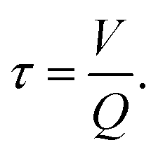
Advanced oxidation of methylene blue was performed in our plasma VFD. Within the device, a vortex is created at the base of the tube, and centrifugal forces create and sustain a thin liquid fluid on the interior surface of the glass tube. Under continuous flow operating conditions at fixed rotational speed and tilt angle, the volume of fluid retained within the device is constant. Under these conditions, the film thickness is controlled by the set rotational speed. Within this microfluidic platform, the residence time of the fluid in the device (τ) is proportional to the fluid volume retained in the device (V) divided by the incoming fluid flow rate (Q),
 | (1) |
Therefore, at a constant rotational speed and tilt angle, the flow rate of solution into the device can be used to adjust the residence time of the fluid in the device. This in turn controls the exposure of the solution to the non-thermal plasma.
In Fig. 2, we present a photo of the methylene blue (MB) stock solution, and the MB solutions following continuous flow non-thermal plasma processing at 8000 rpm for different flow rates. Here the advanced oxidation facilitated by the non-thermal plasma oxidizes the MB, and the solution goes from blue to near colourless. The mechanism for MB degradation within a plasma (oxidation by OH radicals and H2O2 and decomposition by energetic electrons) have previously been established.26–28 The efficiency of the degradation process was characterised using UV-vis spectroscopy, with example spectra for the processed solutions shown in Fig. 2b. These spectra illustrate that the oxidation process has removed the characteristic absorptions of the MB solution in the 550–710 nm region, and that the degree of this decrease in absorption correlates to the increased residence time (inverse flow rate) within the VFD. This degradation process was also confirmed and supported by liquid chromatography mass spectrometry, which is discussed in detail in the ESI.†
 | ||
| Fig. 2 (a) [From left to right] Photo of methylene blue (MB) stock solution (50 mg L−1), and plasma treated MB solutions at 8000 rpm for flow rates of 1.0 mL min−1, 0.5 mL min−1, 0.2 mL min−1 and 0.1 mL min−1 (b) UV-vis spectra of the initial MB solution and plasma treated solutions for different flow rates (FR) at 8000 rpm. | ||
To assess the performance of plasma processing in thin films, the advanced oxidation of MB was performed for rotational speeds of 6000, 7000 and 8000 rpm using the flow rates of 1.0, 0.5, 0.2 and 0.1 mL min−1. The concentration of MB remaining in solution after the plasma treatment was then determined using the intensity of the characteristic MB 660 nm peak. In Fig. 3 we present the percentage of MB that remains in solution after the advanced oxidation plasma treatment. Here the fastest flow rate of 1.0 mL min−1, the MB dye remaining is independent of the devices rotational speed. This suggests that the degradation is limited by the production of oxidising species provided by the plasma at this high flow rate, so that a constant amount of solution is flowing through the device without treatment. However, as we reduce the flow rate to 0.5 and 0.2 mL min−1, we find that the amount of dye removed increases with increasing rotational speed. This suggests that we have entered a regime where the treated volume of liquid is no longer limited by the availability of the advanced oxidation species produced by the plasma. At flow rates of 0.1 mL min−1, we observe that all rotational speeds give comparable quantities of MB remaining, indicating that the treatment time is sufficiently long that within the mixed film the MB is oxidised equivalently in all cases.
 | ||
| Fig. 3 The residual MB remaining after the oxidative plasma treatment in a VFD at different flow rates (exposure time to the plasma) for different rotational speeds. | ||
In order to quantify the present observations, we consider the properties of the fluid within the rotating device. A complete fluid dynamics description of the fluid motion is complicated by the fluid viscosity, vibrations,33 and the tilt angle destroying the cylindrical symmetry through a decoupling of the rotational and gravitational axes. Therefore to gain insights into the fluid dynamics, we attempt to describe the boundary surface of the fluid. At this interface, the rotational and gravitational forces experience by the fluid should be normal to the fluid surface. The height, z, as a function of the radius from the tube axis, r, can be expressed through:
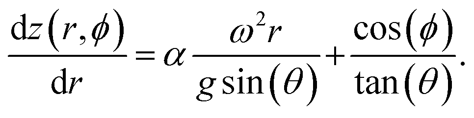 | (2) |
Here ω is the angular frequency, θ, is the tilt angle, and ϕ, is the polar angle around the rotational axis. Within this model, we found it necessary to introduce the empirical parameter α to account for the viscosity and behaviour with respect to the tilt angle. This can be solved for the continuous flow case to obtain the height of the fluid surface as a function of the radius and polar angle for the boundary conditions of the fluid dictated by the physical dimensions of the tube (height, h = 195 mm; internal radius, rmax = 8.8 mm). Here we assume that under continuous flow where fluid is exiting the tube, the height of the fluid is equal to the tube height at the maximum radius for the polar angle ϕ = 0°. This profile gives the minimum radius, where the profile intersects the hemispherical tube base. We assume that in the vortex of the base at the tube, the fluid maintains this minimum radius. The height profile defining the fluid surface becomes:
 | (3) |
From this surface profile of the fluid, the volume of the fluid retained within the tube can be obtained through numerical integration, assuming a uniform density of fluid between the outer tube wall and the fluid surface.
To determine the empirical parameters, and assess the predictive power of the model, the volume of water confined within the rotating tube for a range of tilt angles and rotational speeds has been observed, with these values being compared to the calculated values in Fig. 4a. These measurements were performed by weighing the volume of water retained in the tube after spinning up an excess volume of fluid to the set rotational speed at the specified tilt angle. The α parameter was then adjusted for each tilt angle to best reproduce the measured volumes for the different rotational speeds. Here α ranged from 1.11 to 0.80 for θ between 30 and 90°, respectively. According to Fig. 4a, the model reproduces the characteristic behaviour of the volume for the various tilt angles and rotational speeds, particularly at the higher rotational speeds 5000 rpm and above. This model can therefore be used to provide quantitative insights into the fluid properties.
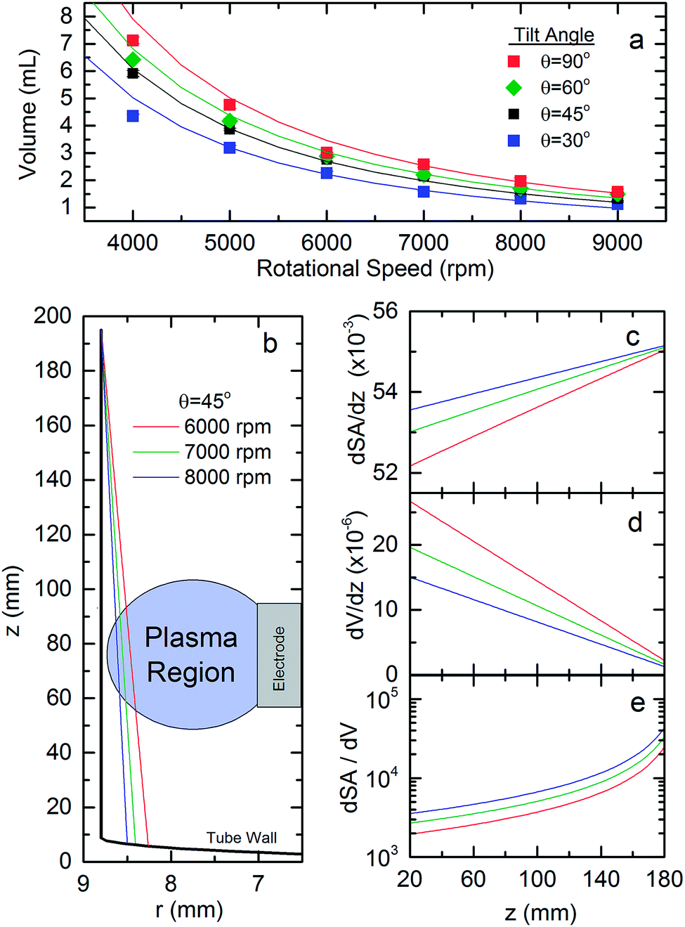 | ||
| Fig. 4 (a) The experimental (symbols) and modelled (curves, coloured to match experiment) for the fluid volume retained in the tube for different tilt angles at various rotational speeds. (b) The fluid film profile in the tube (rmax = 8.8 mm, h = 195 mm) at 6000, 7000 and 8000 rpm rotational speeds. Also shown is the active plasma region. The elements of (c) interior surface area of the fluid (dSA/dz, m), (d) the fluid volume (dV/dz, m2) and (e) the surface area to volume ratio (dSA/dV, m−1) as a function of the height up the tube for rotational speeds of 6000, 7000 and 8000 rpm. | ||
From our fluid model, in Fig. 4 we also present the film profile in the rotating test tube (b), and derivatives of the surface area (c), volume (d) and surface area to volume ratio (e) with respect to the height up the tube for the fixed tilt of 45° at rotational speeds of 6000, 7000 and 8000 rpm. Note that at these high rotational speeds, the film thickness is largely uniform with respect to the polar angle about the rotational axis. Here we observe that the maximum film thickness at the base of the tube decreases from 530 to 294 μm as the rotational speed increases from 6000 to 8000 rpm. In the region of the plasma electrode (z ∼ 60 mm) the film thickness also decreases with increasing rotational speed, being 380, 280 to 210 μm for 6000, 7000 and 8000 rpm, respectively. Despite there being significant variations in the film thickness, the surface area of the film remains largely constant, Fig. 4c, being upwards of 94% of the tubes interior surface area. The volume element of the film in the plasma region, however, decreases by 26% and 44% in going from 6000 rpm to 7000 and 8000 rpm, respectively. This variation in the film properties translates to an increase in the surface to volume ratio element of the film at 6000 rpm by a factor of 1.4 and 1.8 for 7000 and 8000 rpm respectively. We believe that it is this increase in the surface area to volume ratio in the plasma region that improves the plasma liquid processing efficiency with increasing rotational speed. This builds on earlier studies which have highlighted the importance of chemical processing at the plasma liquid interface,12 with the movement of particles into and out of this region also being important for processing efficiency.
What is particularly remarkable about the present result is that the residence time in the device is directly proportional to the volume contained in the device. The exposure time of the fluid to the plasma therefore decreases as the rotational speed increases. This observation highlights that plasma processing in thin-liquid films may be more effective than purely increasing the exposure time to the plasma. These results highlight that within the VFD processing platform, the dynamic mixing inherent to the technology22 and the ability to increase the surface to volume ratio of the thin-film increases the efficiency in which active species in the plasma can penetrate into the thin film to stimulate chemical processes. The advantages of the present thin-film processing strategy for flux-driven chemical processes should facilitate improvements in designing chemical reactors. Specifically, this strategy can improve the feasibility of chemical production through maximising chemical conversion and reducing energy costs associated with flux generation. While the present investigation focused on strategies for improving conversion efficiency in plasma–liquid reactors, strategies for improving yield per energy input are also an important consideration for optimal reactor design. While we have made no attempts to optimise the yield of our reactor, for completeness these details are discussed in the ESI,† where we also compare the present reactors performance in degrading MB to previously reported values. We note that neutron imaging techniques are currently being used to further characterise and improve our understanding of the fluid dynamics in the VFD.35 The present investigation also provides a physical basis for understanding how the VFD platform improves oxidation of N-acetyl cysteine over batch conditions,36 and how such reactions may be further optimised.
Conclusions
We have demonstrated a new continuous flow plasma chemical processing platform for performing advanced oxidations. Further, though the ability to control the liquid film thickness within the device, we have demonstrated flux driven chemical processing can be improved through film thinning without a reduction in the volumetric treatment rate. This observation has general applicability for other flux driven chemical processing techniques, such as photo-redox, photo-catalysis and electrochemistry. As some of these techniques require high energy input, the present devices ability to improve chemical conversion may assist in the scale out of some chemical processing to industry. The described film thinning techniques may therefore reduce the environmental and economic impact of chemical processing through more efficient energy usage, in line with improved green chemistry metrics. The efficiency and scalability of this technology through combining multiple reactors in parallel or increasing the size of the plasma region will be assessed in future work.Conflicts of interest
There are no conflicts to declare.Acknowledgements
The authors acknowledge partial financial support of this research by the Australian Research Council and the Government of South Australia. We thank Dr Xianjue Chen and Mr Ashley Blythe for assistance with some experiments relating to this work. The authors gratefully acknowledge the assistance provided by Dr Daniel Jardine of Flinders Analytical for the LCMS analysis.References
- G. M. Whitesides, Nature, 2006, 442, 368–373 CrossRef CAS PubMed.
- B. Gutmann, D. Cantillo and C. O. Kappe, Angew. Chem., Int. Ed., 2015, 54, 6688–6728 CrossRef CAS PubMed.
- J. Wegner, S. Ceylan and A. Kirschning, Adv. Synth. Catal., 2012, 354, 17–57 CrossRef CAS.
- Y. Su, N. J. W. Straathof, V. Hessel and T. Noël, Chem.–Eur. J., 2014, 20, 10562–10589 CrossRef CAS PubMed.
- Y. Matsushita, T. Ichimura, N. Ohba, S. Kumada, K. Sakeda, T. Suzuki, H. Tanibata and T. Murata, Pure Appl. Chem., 2007, 79, 1959 CrossRef CAS.
- K. Watts, A. Baker and T. Wirth, J. Flow Chem., 2014, 4, 2 CrossRef.
- S. V. Ley, D. E. Fitzpatrick, R. M. Myers, C. Battilocchio and R. J. Ingham, Angew. Chem., Int. Ed., 2015, 54, 10122–10136 CrossRef CAS PubMed.
- C. Qiang, L. Junshuai and L. Yongfeng, J. Phys. D: Appl. Phys., 2015, 48, 424005 CrossRef.
- K. Bazaka, M. V. Jacob and K. Ostrikov, Chem. Rev., 2016, 116, 163–214 CrossRef CAS PubMed.
- P. J. Bruggeman, M. J. Kushner, B. R. Locke, J. G. E. Gardeniers, W. G. Graham, D. B. Graves, R. C. H. M. Hofman-Caris, D. Maric, J. P. Reid, E. Ceriani, D. F. Rivas, J. E. Foster, S. C. Garrick, Y. Gorbanev, S. Hamaguchi, F. Iza, H. Jablonowski, E. Klimova, J. Kolb, F. Krcma, P. Lukes, Z. Machala, I. Marinov, D. Mariotti, S. M. Thagard, D. Minakata, E. C. Neyts, J. Pawlat, Z. L. Petrovic, R. Pflieger, S. Reuter, D. C. Schram, S. Schröter, M. Shiraiwa, B. Tarabová, P. A. Tsai, J. R. R. Verlet, T. v. Woedtke, K. R. Wilson, K. Yasui and G. Zvereva, Plasma Sources Sci. Technol., 2016, 25, 053002 CrossRef.
- O. Takai, Pure Appl. Chem., 2008, 80, 2003–2011 CrossRef CAS.
- P. Bruggeman and C. Leys, J. Phys. D: Appl. Phys., 2009, 42, 053001 CrossRef.
- D. Mariotti, J. Patel, V. Švrček and P. Maguire, Plasma Processes Polym., 2012, 9, 1074–1085 CrossRef CAS.
- D. Mariotti, V. Švrček, J. W. J. Hamilton, M. Schmidt and M. Kondo, Adv. Funct. Mater., 2012, 22, 954–964 CrossRef CAS.
- P. Rumbach, M. Witzke, R. M. Sankaran and D. B. Go, J. Am. Chem. Soc., 2013, 135, 16264–16267 CrossRef CAS PubMed.
- P. Rumbach, D. M. Bartels, R. M. Sankaran and D. B. Go, Nat. Commun., 2016, 7, 11911 CrossRef PubMed.
- P. Rumbach, D. M. Bartels, R. M. Sankaran and D. B. Go, Nat. Commun., 2015, 6, 7248 CrossRef CAS PubMed.
- R. Gopalakrishnan, E. Kawamura, A. J. Lichtenberg, M. A. Lieberman and D. B. Graves, J. Phys. D: Appl. Phys., 2016, 49, 295205 CrossRef.
- P. T. Anastas and J. C. Warner, Green Chemistry: Theory and Practice, Oxford University Press, 1998 Search PubMed.
- P. T. Anastas and J. B. Zimmerman, Environ. Sci. Technol., 2003, 37, 94A–101A CrossRef PubMed.
- D. B. Jones, X. Chen, A. Sibley, J. S. Quinton, C. J. Shearer, C. T. Gibson and C. L. Raston, Chem. Commun., 2016, 52, 10755–10758 RSC.
- L. Yasmin, X. Chen, K. A. Stubbs and C. L. Raston, Sci. Rep., 2013, 3, 2282 CrossRef PubMed.
- B. Jiang, J. Zheng, S. Qiu, M. Wu, Q. Zhang, Z. Yan and Q. Xue, Chem. Eng. J., 2014, 236, 348–368 CrossRef CAS.
- B. P. Dojčinović, G. M. Roglić, B. M. Obradović, M. M. Kuraica, M. M. Kostić, J. Nešić and D. D. Manojlović, J. Hazard. Mater., 2011, 192, 763–771 CrossRef PubMed.
- H. Krause, B. Schweiger, E. Prinz, J. Kim and U. Steinfeld, J. Electrost., 2011, 69, 333–338 CrossRef CAS.
- F. Huang, L. Chen, H. Wang and Z. Yan, Chem. Eng. J., 2010, 162, 250–256 CrossRef CAS.
- M. Magureanu, D. Piroi, F. Gherendi, N. Mandache and V. Parvulescu, Plasma Chem. Plasma Process., 2008, 28, 677–688 CrossRef CAS.
- T. Maehara, K. Nishiyama, S. Onishi, S. Mukasa, H. Toyota, M. Kuramoto, S. Nomura and A. Kawashima, J. Hazard. Mater., 2010, 174, 473–476 CrossRef CAS PubMed.
- S. D. Anghel, D. Zaharie-Butucel and I. E. Vlad, J. Electrost., 2015, 75, 63–71 CrossRef CAS.
- M. Magureanu, C. Bradu, D. Piroi, N. Mandache and V. Parvulescu, Plasma Chem. Plasma Process., 2013, 33, 51–64 CrossRef CAS.
- S. Ikoma, K. Satoh and H. Itoh, Electr. Eng. Jpn., 2012, 179, 1–9 CrossRef.
- M. N. Gandy, C. L. Raston and K. A. Stubbs, Chem. Commun., 2015, 51, 11041–11044 RSC.
- J. Britton, K. A. Stubbs, G. A. Weiss and C. L. Raston, Chem.–Eur. J., 2017, 23, 13270–13278 CrossRef CAS PubMed.
- C. A. Clark, D. S. Lee, S. J. Pickering, M. Poliakoff and M. W. George, Org. Process Res. Dev., 2016, 20, 1792–1798 CrossRef CAS.
- J. T. Solheim, F. Salvemini, S. B. Dalziel and C. L. Raston, 2017, to be submitted.
- S. J. Pye, S. J. Dalgarno, J. M. Chalker and C. L. Raston, Green Chem., 2017 Search PubMed , submitted.
Footnote |
| † Electronic supplementary information (ESI) available. See DOI: 10.1039/c7ra09559g |
| This journal is © The Royal Society of Chemistry 2017 |