 Open Access Article
Surface modification of piperazine-based nanofiltration membranes with serinol for enhanced antifouling properties in polymer flooding produced water treatment
Ruijun Zhang a,
Shuili Yu*a,
Wenxin Shi*a,
Xiaoying Wangb,
Jun Chengc,
Zhiqiang Zhanga,
Li Lia,
Xian Baoa and
Bing Zhanga
aState Key Laboratory of Urban Water Resource and Environment, School of Municipal and Environmental Engineering, Harbin Institute of Technology, Harbin 150090, P. R. China. E-mail: ysl@tongji.edu.cn; swx@hit.edu.cn
bSchool of Architectural Engineering, Sanming University, Sanming 365004, P. R. China
cSchool of Chemical Engineering, Northeast Electric Power University, Jilin 132012, P. R. China
First published on 17th October 2017
Abstract
In order to deal with the membrane fouling problem when treating the polymer flooding produced water (PFPW) with a typical thin film composite (TFC) nanofiltration (NF) membrane, a facile and effective serinol surface modification method has been introduced in this study, which is based on the membrane fouling mechanism proposed in our previous research. Serinol molecules were grafted on the nascent piperazine-based PA-TFC membrane through the acylation reaction between the serinol molecule’s amino group and the nascent membrane’s residual acyl chloride group. A series of characterizations indicated that this modification process could enhance membrane hydrophilicity and decrease the surface carboxyl density without changing the membrane’s morphology. Compared with the unmodified PA-TFC membrane, the serinol-grafted PA-TFC membrane had higher water permeability, stronger antifouling ability and equivalent solute rejection, which would be rather meaningful for improving membrane performance when treating PFPW.
1. Introduction
With the surge in population growth, urban development, and industrialization around the world, new water sources, such as those provided by the treatment of low-quality local water sources, water conservation, regional water transfers, sea water desalination as well as wastewater recycling and reuse, are required to meet the demand for fresh water.1 As one of the most important industrial wastewater sources, the amount of water produced from the petroleum industry is extremely huge, the production of which was more than 2.5 billion barrels per day in 2015 according to predictions.2 Directly discharging produced water will not only result in environmental pollution, but also in a waste of water resources, especially for water-deficient areas. Therefore, reclamation of this industrial wastewater through proper treatments has become the consensus of many researchers.2,3Polymer flooding produced water (PFPW) is a kind of produced water which is co-produced in the process of polymer flooding oil extraction. Recent advancements have confirmed the feasibility and potential of applying reverse osmosis (RO) and nanofiltration (NF) technologies to produced water management.4–7 According to our previous research, it is reasonable to recycle PFPW for polymer flooding oil exploitation in an internal reuse pattern after advanced treatment with a commercial polyamide NF membrane.8 However, membrane fouling, which is dominantly induced by anionic polyacrylamide (APAM), is a major problem that limits further applications. Based on previously proposed fouling and cleaning mechanisms, Ca2+ in feed solutions could act as a “bridge” through complexation interactions between the carboxyls on the membrane surface and those on APAM, as well as those on different APAM molecules, thus enhancing membrane fouling.8,9 Surface modification through grafting techniques has been used to modify surfaces and to improve the antifouling properties of membranes.10,11 In consideration of the fact that carboxyls on composite polyamide NF membrane surfaces result from the hydrolysis of unreacted acyl chloride groups, covalent grafting of these unreacted acyl chloride groups before their hydrolysis and the replacement of the carboxyls for other hydrophilic groups is expected to produce the desired NF membranes.
Some studies have been conducted to modify the polyamide membrane with different monomers, which demonstrate the effectiveness of this method to improve membrane performance. For instance, Yan et al.12 studied the grafting of triethanolamine (TEOA) on a nascent polyamide NF membrane through an esterification reaction between the hydroxyl groups of TEOA and the residual acyl chloride groups on the membrane. The modified membrane had higher hydrophilicity, water flux and antifouling ability against hydrophobic foulants. Zhu et al.13 made use of the grafting reaction between the poly(amidoamine) dendrimer (PAMAM) and the residual acyl chloride groups on a nascent membrane. The PAMAM grafting can decrease the membrane pore size and provide positively charged functional groups, thus making the membrane positively charged. In this way, the membrane hydrophilicity and water permeability were improved. Meanwhile, the modified membrane got higher rejections against most tested heavy metals. In the research of Wang et al.,14 poly(ethyleneimine) (PEI) was used to graft residual acyl chlorides after the reaction between trimesoyl chloride (TMC) and polydopamine (PDA). The deposition of PEI effectively decreased the membrane pore size and surface roughness. Moreover, the membrane’s long-term stability was also verified. The above research results indicate that it is possible to tailor membranes so that the antifouling property in PFPW treatment is enhanced through the grafting of appropriate monomers with residual acyl chloride groups on the nascent membrane.
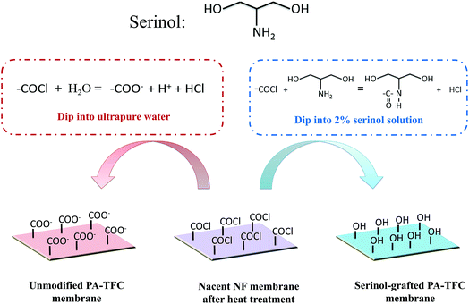
Serinol (2-amino-1,3-propanediol), which includes one amino group and two hydroxyl groups (as shown in Fig. 1), is an important intermediate with good chemical stability and water solubility that is widely used in medicine and chemical industries.15 As the reaction rate constant of amino groups is a few orders of magnitude higher than that of hydroxyl groups,16 the amino and hydroxy groups present in serinol cannot simultaneously react with the acyl chloride groups under relatively mild conditions without a catalyzer. In our previous study, serinol was used as a water soluble monomer to prepare a TFC NF membrane with 4-dimethylaminopyridine (DMAP) as a catalyst,17 which demonstrated that polymerization reactions cannot happen without a catalyzer. In this study, serinol has been adopted to modify the piperazine-based TFC-NF membrane through the acylation reaction between the amino groups of serinol and the residual acyl chloride groups on the nascent membrane, by pouring the serinol-aqueous solution on the surface of the nascent TFC-NF membrane, so that the number of residual carboxyls on the membrane surface decreases and the membrane hydrophilicity is enhanced. In order to demonstrate the effectiveness of this modification method, ATR-FTIR, AFM, FESEM, contact angle geometry, surface zeta potential analysis, and a Toluidine blue O (TBO) technique were employed to study the unmodified TFC-NF membrane and the serinol-grafted TFC-NF membrane. Finally, the membrane performance including the flux decline trend and the solute rejection was evaluated by treating the model PFPW.
2. Materials and methods
2.1. Materials
Flat-sheet polysulfone (PS) substrate membrane with a molecular weight cut-off (MWCO) of around 60![[thin space (1/6-em)]](https://www.rsc.org/images/entities/char_2009.gif) 000 g mol−1 was purchased from Tangshan SEAPS Science and Technology Co., Ltd. Serinol (2-amino-1,3-propanediol, >97.0%), and n-hexane were obtained from Sinopharm Chemical Reagent Co., Ltd. (Shanghai, China). TMC (>98.0%) was purchased from Tokyo Chemical Industry (Shanghai, China). Piperazine (PIP, >99.0%), triethylamine (TEA, >99.5%), and a series of PEG compounds with different molecular weight cut-offs were purchased from Aladdin Industrial Corporation (Shanghai, China). Toluidine blue O (TBO, >85%) purchased from J&K Scientific (Beijing, China) was used to characterize carboxyl group density on the TFC membrane surface. The APAM and crude oil used for preparing model PFPW was provided by the 5th Daqing oil production factory. Ultrapure water was produced from a Milli-Q ultrapure water purification system.
000 g mol−1 was purchased from Tangshan SEAPS Science and Technology Co., Ltd. Serinol (2-amino-1,3-propanediol, >97.0%), and n-hexane were obtained from Sinopharm Chemical Reagent Co., Ltd. (Shanghai, China). TMC (>98.0%) was purchased from Tokyo Chemical Industry (Shanghai, China). Piperazine (PIP, >99.0%), triethylamine (TEA, >99.5%), and a series of PEG compounds with different molecular weight cut-offs were purchased from Aladdin Industrial Corporation (Shanghai, China). Toluidine blue O (TBO, >85%) purchased from J&K Scientific (Beijing, China) was used to characterize carboxyl group density on the TFC membrane surface. The APAM and crude oil used for preparing model PFPW was provided by the 5th Daqing oil production factory. Ultrapure water was produced from a Milli-Q ultrapure water purification system.
2.2. Preparation of the serinol-grafted PA-TFC membrane
All operations were performed in a clean room with a constant relative humidity of 60 ± 5% and temperature of 30 ± 1 °C. The substrate membranes were first immersed in a 0.5% ethanol aqueous solution for 8 h and then transferred to ultrapure water for ultrasonic cleaning for 2 min. Subsequently, the substrate membranes were immersed in ultrapure water for another 12 h. The preparation of the serinol-grafted PA-TFC NF membrane is schematically illustrated in Fig. 1. The NF membrane was fabricated via interfacial polymerization of PIP and TMC on the support membrane. The cleaned substrate membrane clamped in a polytetrafluoroethylene (PTFE) frame was firstly coated with a 0.6% (w/v) PIP aqueous solution for 120 s, the pH of which was adjusted to 11.5 using TEA. Filter paper was used to remove excess PIP solution on the membrane surface. Then the 0.025% (w/v) TMC n-hexane solution was immediately poured on the membrane surface and reacted for 10 s. Subsequently, the membrane surface was rinsed thoroughly with the clean n-hexane followed by heat treatment at 50 °C for 15 min. The rinsing process aims to remove the residual TMC monomer and ensures the grafting reaction between serinol and the residual acyl chloride on the polyamide backbone. Afterwards, the surface of the nascent PA-TFC membrane was coated with a 2.0% (w/v) serinol aqueous solution for 15 min at 50 °C, the pH of which was adjusted to 11.5 with TEA. Finally, the membranes were washed thoroughly with ultrapure water and were stored in ultrapure water at 4 °C prior to use.2.3. Characterization of the membrane surface
Attenuated total reflectance-Fourier transform infrared spectroscopy (ATR-FTIR, Thermo Scientific, Nicolet iS50, USA) was used to analyse the chemical structure of different membranes. Atomic force microscopy (AFM, Bioscope, Veeco, USA) was used to analyse the 3D-morphology and roughness of different membranes. The scanning pattern of the probe was in the tapping mode and conducted in air. The root mean square roughness (RMS) was calculated through the height profile of each 5.0 μm × 5.0 μm. The surface morphologies of the membranes were visualized using a field emission scanning electron microscope (FESEM, ZEISS, SUPRA 55, Germany). The membrane samples were sputtered with gold before FESEM analysis. Static contact angles of various membranes were measured with a contact angle goniometer (SL200B3, Solon, China) by the sessile drop method (0.1 μL). Each CA value was the average of three different positions on the same membrane piece. Contact angles were calculated using the circle fitting method. An electrokinetic analyzer (EKA, Anton Paar GmbH, Austria) was adopted to measure the membrane surface streaming potential using a 0.001 mol L−1 KCl aqueous solution, and the pH was adjusted using 0.1 M HCl or NaOH. Then the surface zeta potential was calculated from the measured streaming potential according to the Helmholtz–Smoluchowski equation.18The membrane surface carboxyl density was calculated based on the TBO technique proposed by Tiraferri et al.19 Briefly, the TFC NF membrane was sealed with a PTFE frame to leave only the active layer exposed. The exposed active layer was circular with a diameter of 9.0 cm. Then, the active layer of the TFC membrane was soaked in a freshly prepared TBO solution (2 mmol L−1) for 30 min, the pH of which was adjusted to 11 using NaOH, so as to bind the positively charged TBO molecules to the deprotonated carboxylic acid groups on the TFC membrane surface. Then the TFC membrane surface was rinsed with a dye-free NaOH solution (pH 11) for 5 h to remove the unbound TBO molecules. Finally, the TFC membrane was immersed into a NaCl solution for 30 min (pH was adjusted to 2 using HCl) to elute the bonded TBO dye from the active layer. The absorbance of the eluent was measured at a wavelength of 630 nm to calculate the surface carboxyl group density.20
2.4. Evaluation of the membrane water flux and solute rejection
The membrane water flux and solute rejection were evaluated by the cross-flow NF set-up as described in our previous study under the constant trans-membrane pressure of 5.0 bar at 25.0 °C.8 The effective membrane surface area in the membrane cell is 0.0025 m2. Each new membrane was pre-pressured at 10.0 bar with ultrapure water until the water flux became constant. Membrane water permeability (P0) was subsequently measured using the following equation:21
 | (1) |
Membrane salt rejection was determined with a single-solute aqueous solution containing salts of NaCl, MgCl2, MgSO4 or Na2SO4. The concentration of the inorganic salt was 1000 mg L−1. The salt rejection was obtained by measuring the conductivity of the aqueous solution using a conductivity meter (DDSJ-308A, Shanghai INESA Scientific Instrument, China). PEG 200, PEG 400, PEG 600, PEG 800 and PEG 1000 solutions with concentrations of 200 mg L−1 were used to determine the membrane MWCO. A rejection curve was plotted according to the different PEG rejections. The MWCO corresponding to a rejection of 90% was regarded as the membrane MWCO. The concentrations of PEG were determined using a total organic carbon analyzer (TOC-VCNP, Shimadzu, Japan). The observed solute rejection R (%) was calculated according to the following equation:
 | (2) |
2.5. Cross-flow testing of membrane performance in treating the model PFPW
The prepared NF membranes were further used to treat the model PFPW. Water quality of the model PFPW is illustrated in Table 1. The method of preparation of the model PFPW is described in detail in our previous study.8 The new NF membranes were pre-pressured with ultrapure water (temperature: 25 °C) at 10.0 bar until the water flux was constant. Then the baseline was obtained by treating the ultrapure water (temperature: 25 °C, trans-membrane pressure: 5.0 bar and cross-flow velocity: 7.0 cm s−1) for 2 h. Subsequently, the ultrapure water in the feed tank was replaced by the model PFPW. The filtration process was conducted for four cycles. Each cycle lasted 8 h. After each cycle, the membrane was flushed with the feed water at a cross-flow velocity of 15.0 cm s−1 for 1 h. The flux decline curve was obtained by treating the model PFPW with the same starting water flux of 40 L m−2 h−1. The rejection of different ions was determined by inductively coupled plasma atomic emission spectrometry (ICP-AES, PerkinElmer, Plasma1000, USA) and ion chromatography (IC, Thermo Scientific, ICS-600, USA).| Parameter | Value |
|---|---|
| pH | 8.5–8.8 |
| TDS | Around 5000 mg L−1 |
| Na+ | 1442.63 ± 3.01 mg L−1 |
| K+ | 44.83 ± 0.10 mg L−1 |
| Ca2+ | 7.21 ± 0.19 mg L−1 |
| Mg2+ | 75.76 ± 0.09 mg L−1 |
| Cl− | 1195.71 ± 0.69 mg L−1 |
| HCO3− | 2178.57 ± 1.41 mg L−1 |
| SO42− | 55.17 ± 0.12 mg L−1 |
| APAM | 30.00 mg L−1 |
| Crude oil | 1.50 mg L−1 |
3. Results and discussion
3.1. Physicochemical properties of the membrane
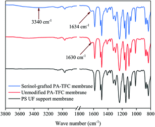
ATR-FTIR was employed to analyze the chemical structure of the PS supporting membrane, the unmodified PA-TFC membrane and the serinol-grafted PA-TFC membrane. The results are presented in Fig. 2. Compared with the PS support membrane, the new peak at 1630 cm−1 was related to the stretching vibration of carbonyls in amide bonds present in the unmodified PA-TFC membrane. As for the serinol-grafted PA-TFC membrane, the peak related to the stretching vibration of carbonyls in amide bonds shifted to 1634 cm−1 because the secondary amide formed by the primary amino group in the serinol molecule can result in shifts to higher wavenumbers.22–24 No new peak appears around 1725 cm−1, which implies that the hydroxyl group cannot react with the acyl chloride and form ester bonds.25,26 Moreover, the new peak at 3340 cm−1 can be attributed to the hydroxyl groups of serinol, which were successfully grafted on the modified membrane, because the stretching vibration of hydroxyl groups can produce a broad peak in the range of 3200–3500 cm−1.27,28 The grafted hydroxyl groups are expected to decrease the number of carboxyl groups and enhance membrane hydrophilicity.The morphologies of the unmodified PA-TFC membrane and of the serinol-grafted PA-TFC membrane were investigated by AFM and FESEM. Additionally, the RMS roughness of the two membranes was obtained from the AFM images with Nanoscope Analysis software version 1.40. The results are presented in Fig. 3 and 4. AFM images in Fig. 3 imply that both the surface of the serinol-grafted PA-TFC membrane and that of the unmodified PA-TFC membrane were rather smooth. The average RMS roughness only increased to 5.09 nm from 4.47 nm after grafting. The RMS roughness difference is so small that it should be within the experimental error. Therefore, it can be said that the grafting process with serinol did not change the membrane morphology in any obvious way. Similarly to the results of AFM, the FESEM images further confirmed the above conclusion, suggesting that the modification process would not influence the membrane’s surface structure. The above phenomenon is because no cross-linking reaction could happen during the grafting process with serinol, as there was only one reactive group (the amino group) in the serinol molecule which could react with the residual acyl chloride groups on the nascent membrane. This is also the difference between our modification process and those proposed by other researchers.12,13
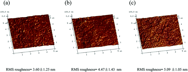 | ||
| Fig. 3 AFM images of (a) the UF substrate membrane, (b) the top layer of the unmodified PA-TFC membrane and (c) the top layer of the serinol-grafted PA-TFC membrane. | ||
 | ||
| Fig. 4 FESEM images of (a) the UF substrate membrane, (b) the top layer of the unmodified PA-TFC membrane and (c) the top layer of the serinol-grafted PA-TFC membrane. | ||
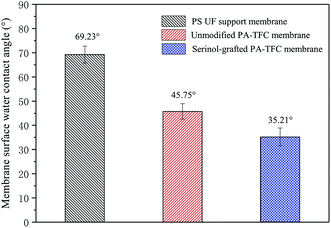
The membrane hydrophilicity was evaluated by water contact angles. The contact angles of the PS UF support membrane, the unmodified PA-TFC membrane, and the serinol-grafted PA-TFC membrane were measured and are displayed in Fig. 5. The water contact angle of the PS supporting membrane was 69.23°, while that of the unmodified PA-TFC membrane was 45.75°. After modification with serinol, the water contact angle of the serinol-grafted PA-TFC membrane decreased to 35.21°. The FTIR spectra of the serinol-grafted PA-TFC membrane in Fig. 2 indicate that serinol has been successfully grafted on the PA-TFC membrane. The hydroxyl groups in the serinol molecule can effectively enhance the membrane hydrophilicity, which is beneficial to both water permeation and fouling resistance against hydrophobic foulants.
The charge properties of the unmodified PA-TFC membrane and those of the serinol-grafted PA-TFC membrane were evaluated by zeta-potential measurements. Surface zeta-potentials at different pH are shown in Fig. 6. As illustrated in Fig. 6, the grafting process with serinol decreased the absolute value of the PA-TFC membrane’s negative charge. The amphoteric surface characteristic of a typical PA-TFC membrane is due to its residual carboxyl groups and amino groups.18 The measured zeta potential should be the trade-off between carboxyl groups and residual amino groups. Theoretically, the amino group number of the modified and unmodified PA-TFC membranes should be the same, so the change of the serinol-grafted PA-TFC membrane’s surface zeta-potential should result from the number of its residual carboxyl groups. The isoelectric points of the modified and unmodified membranes were both between 4 and 5. When the solution pH was under 5, the charge properties of these two membranes were similar on taking the experimental error into consideration. When the solution pH was higher than 5, the absolute value of the serinol-grafted PA-TFC membrane’s negative charge was smaller than that of the unmodified membrane, which should be a result of the reaction between serinol and acyl chloride as illustrated in Fig. 1. Furthermore, based on the mechanism of fouling and cleaning proposed in our previous study,8,9 Ca2+ in the feed solution could act as a “bridge” by complexation interactions between the carboxyls on the membrane surface and those of APAM, as well as those of different APAM molecules, thus enhancing membrane fouling. Therefore, the decrease in carboxyl group numbers is expected to improve the antifouling properties of the membrane when treating PFPW.
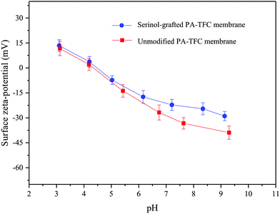 | ||
| Fig. 6 Surface zeta-potentials of different membranes in 1 mM L−1 KCl solution with different pH values at 25 °C. | ||
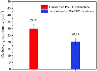
The TBO technique was adopted to quantify the membrane’s surface carboxyl density, so that the serinol grafting process could be characterised from another point of view. As shown in Fig. 7, the grafting process with serinol clearly decreased the membrane surface carboxyl density from 29.96 nm−2 to 20.14 nm−2. The results are consistent with membrane zeta-potential measurements, which demonstrate the successful modification by serinol grafting. The decreased surface carboxyl density will be beneficial to mitigate the complexation interaction between the carboxyls on the membrane surface and those of APAM induced by Ca2+ in feed solutions.
3.2. Membrane permeation properties
The membrane permeation properties, including pure water permeability, salt rejections and molecular weight cut-off (MWCO) of the unmodified PA-TFC membrane and of the serinol-grafted PA-TFC membrane were measured and are shown in Fig. 8(a–c), respectively. The MWCOs of the two membranes were determined according to the neutral solute rejections.29,30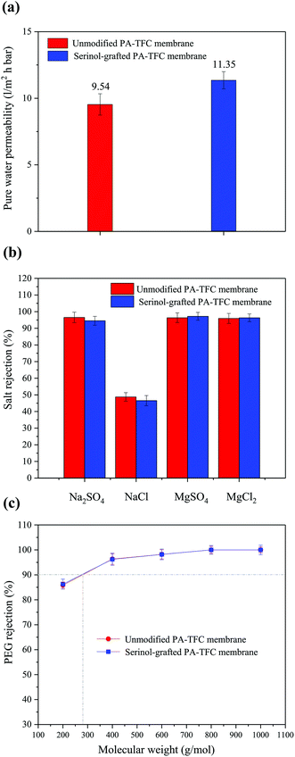 | ||
| Fig. 8 Permeation properties: (a) pure water permeability, (b) salt rejections and (c) PEG rejections of different membranes tested at 0.5 MPa and 25 °C. | ||
As indicated in Fig. 8(a), the unmodified PA-TFC membrane has a pure water permeability of 9.54 L m−2 h−1 bar−1. After modification by serinol grafting, the membrane pure water permeability was clearly improved to 11.35 L m−2 h−1 bar−1. Section 3.1 demonstrated that the serinol grafting process can enhance membrane hydrophilicity, while keeping a similar active layer structure. Therefore, the improved pure water permeability was a result of the higher hydrophilicity, due to enhanced hydrophilicity being favorable for the water molecules’ mass transfer across the active layer.31 Fig. 8(b) indicates that the salt rejections of the unmodified PA-TFC membrane were 96.51% (Na2SO4), 48.76% (NaCl), 96.36% (MgSO4) and 95.94% (MgCl2), respectively. After modification with serinol, the Na2SO4 and NaCl rejections decreased slightly to 94.54% and 46.55%, while the rejections of MgSO4 and MgCl2 remained relatively stable. The slight decrease of the Na2SO4 and NaCl rejections should be induced by the decline of the electrostatic repulsive effect as the active layer’s surface negative charge and carboxyl group density decreased after serinol grafting.32 This phenomenon was similar to the results found by Yan et al.12 Fig. 8(c) suggests that both the unmodified PA-TFC membrane and serinol-grafted PA-TFC membrane had a MWCO around 275 Da. This result verifies that the modification process did not influence the active layer’s compactness and pore size because there was only one reactive group (the amino group) in the serinol molecule that could react with the residual acyl chloride groups on the nascent membrane. Fig. 8(a–c) shows that the modification of the active layer with serinol grafting can obviously improve the water permeability while almost maintaining its desalting ability and neutral solute selectivity.
3.3. Membrane performance in treating the model PFPW
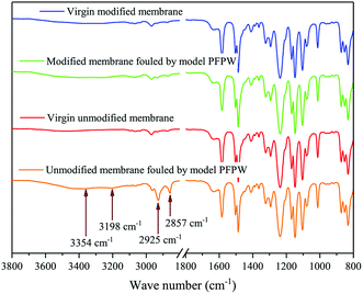
The unmodified PA-TFC membrane and the serinol-grafted PA-TFC membranes were respectively used to treat the model PFPW. The filtration process was conducted for four cycles. Each cycle lasted 8 h. After each cycle, the membrane was flushed with the feed water at a cross-flow velocity of 15.0 cm s−1 for 1 h. The total operation time was 36 h.The flux decline curve was obtained and is shown in Fig. 9(a). The rejection of different solutes, including Ca2+, Mg2+, Na+, K+, SO42−, Cl− and TOC, was measured and is illustrated in Fig. 9(b). As shown in Fig. 9(a), the flux of the unmodified PA-TFC membrane continuously decreased during the filtration process. Although hydraulic cleaning could recover the flux to some extent, the recovery rate was still rather low. At the end of the operation, the normalized flux had decreased to 0.84. In contrast to the unmodified PA-TFC membrane, the serinol-grafted PA-TFC membrane showed obvious antifouling ability. The normalized flux of the serinol-grafted PA-TFC membrane remained relatively stable and had little decline throughout the whole filtration process, which could still reach 0.98 at the end of it. The excellent antifouling ability of the serinol-grafted PA-TFC membrane can be ascribed to its enhanced hydrophilicity and decreased membrane surface carboxyl group density as verified in Section 3.2. Moreover, as the serinol-grafted PA-TFC membrane had higher water permeability, its operation pressure was lower than that of the unmodified PA-TFC membrane in order to keep the same starting flux. The lower operation pressure was also beneficial to mitigate membrane fouling because of its slighter compaction effect. ATR-FTIR was adopted to analyse different NF membranes in order to provide more evidence. The fouled membranes were thoroughly flushed with deionized water before drying. Infrared spectroscopy of the virgin modified membrane, the modified membrane fouled by the model PFPW, the virgin unmodified membrane and the unmodified membrane fouled by the model PEPW are shown in Fig. 10. As indicated in Fig. 10, there are four new peaks in the infrared spectroscopy of the unmodified membrane fouled by the model PFPW. The peaks at 3354 cm−1 and 3198 cm−1 can be attributed to APAM,9 while the peaks at 2925 cm−1 and 2857 cm−1 can be related to the crude oil.9 The new peaks involving APAM and crude oil suggest that the unmodified membrane was seriously fouled by the model PFPW. This is why the membrane flux decreased. As for the modified membrane, no obvious peaks related to APAM and crude oil could be found after filtrating the model PFPW for 32 h. The ATR-FTIR measurements further confirmed that the modification process can effectively improve the membrane antifouling ability.
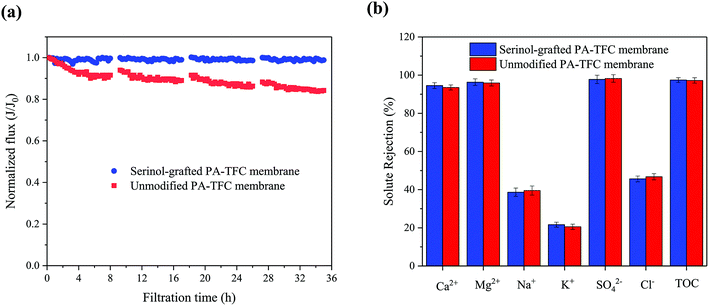 | ||
| Fig. 9 Membrane performance in treating the model PFPW: (a) normalized flux decline curve and (b) different solute rejections of different membranes. | ||
Fig. 9(b) indicates that both the unmodified PA-TFC membrane and the serinol-grafted PA-TFC membrane can effectively reject Ca2+, Mg2+, SO42− and TOC. The high Ca2+ and Mg2+ rejections are extremely meaningful in the case of treating PFPW aiming for reuse in polymer flooding oil extraction, because divalent cations would severely cause the shielding of APAM’s negative charge, lead to the coiling up of linear polymers, and eventually decrease the crude oil recovery.33,34 Moreover, scale control is also very important for oil extraction because the scale formation would block the oil wells and decrease the crude oil recovery. Therefore, the high SO42− rejection is also beneficial to wastewater reuse in polymer flooding oil extraction.
4. Conclusion
In this study, a surface modification method with serinol has been proposed to enhance the antifouling property of the TFC NF membrane applied in polymer flooding produced water treatment. ATR-FTIR confirmed the successful covalent grafting of serinol on the nascent PIP and TMC-based NF membrane. AFM and FESEM characterizations suggested that the modification process did not change the membrane morphology. The contact angle geometer, surface zeta potential analyzer, and the TBO technique indicated that the grafting process effectively improved the membrane hydrophilicity and decreased the surface carboxyl density. The modification of the active layer with serinol grafting can obviously improve the water permeability while almost maintaining its desalting ability and neutral solute selectivity. When treating the model PFPW, the serinol-grafted PA-TFC membrane showed excellent antifouling ability and satisfactory rejections against Ca2+, Mg2+, SO42− and TOC, which are rather meaningful in the case of treating PFPW aiming for reuse in polymer flooding oil extraction.Conflicts of interest
There are no conflicts to declare.Acknowledgements
The authors gratefully acknowledge the financial support provided by Natural Science Foundation of China (NSFC, Grant no. 51578390) and the State Key Laboratory of Urban Water Resource Environment (HIT, Grant no. 2016DX11).References
- M. Elimelech and W. A. Phillip, Science, 2011, 333, 712–717 CrossRef CAS PubMed.
- A. Fakhru’l-Razi, A. Pendashteh, L. C. Abdullah, D. R. A. Biak, S. S. Madaeni and Z. Z. Abidin, J. Hazard. Mater., 2009, 170, 530–551 CrossRef PubMed.
- S. Alzahrani and A. W. Mohammad, Journal of Water Process Engineering, 2014, 4, 107–133 CrossRef.
- S. Alzahrani, A. W. Mohammad, N. Hilal, P. Abdullah and O. Jaafar, Desalination, 2013, 315, 27–32 CrossRef CAS.
- S. Alzahrani, A. W. Mohammad, N. Hilal, P. Abdullah and O. Jaafar, Sep. Purif. Technol., 2013, 118, 324–341 CrossRef CAS.
- V. Pikalov, S. Arrieta, A. T. Jones and J. Mamo, J. Environ. Chem. Eng., 2013, 1, 1341–1349 CrossRef.
- S. Mondal and S. R. Wickramasinghe, J. Membr. Sci., 2008, 322, 162–170 CrossRef CAS.
- R. Zhang, W. Shi, S. Yu, W. Wang, Z. Zhang, B. Zhang, L. Li and X. Bao, Desalination, 2015, 373, 27–37 CrossRef CAS.
- R. Zhang, S. Yu, W. Shi, J. Tian, L. Jin, B. Zhang, L. Li and Z. Zhang, RSC Adv., 2016, 6, 28844–28853 RSC.
- D. Rana and T. Matsuura, Chem. Rev., 2010, 110, 2448–2471 CrossRef CAS PubMed.
- J. M. Gohil and P. Ray, Sep. Purif. Technol., 2017, 181, 159–182 CrossRef CAS.
- F. Yan, H. Chen, L. Yang, Z. Lü, S. Yu, M. Liu and C. Gao, J. Membr. Sci., 2016, 513, 108–116 CrossRef CAS.
- W. P. Zhu, J. Gao, S. P. Sun, S. Zhang and T. S. Chung, J. Membr. Sci., 2015, 487, 117–126 CrossRef CAS.
- T. Wang, H. Qiblawey, E. Sivaniah and A. Mohammadian, J. Membr. Sci., 2016, 511, 65–75 CrossRef CAS.
- L. Liu, J. I. Xiaojun, M. Shen, Y. Tong and H. Huang, Chem. Ind. Eng. Prog., 2014, 33, 2722–2728 CAS.
- H. G. Elias, Principles of Polymerization, Springer, US, 1977 Search PubMed.
- R. Zhang, S. Yu, W. Shi, W. Wang, X. Wang, Z. Zhang, L. Li, B. Zhang and X. Bao, J. Membr. Sci., 2017, 542, 68–80 CrossRef CAS.
- A. E. Childress and M. Elimelech, J. Membr. Sci., 1996, 119, 253–268 CrossRef CAS.
- A. Tiraferri and M. Elimelech, J. Membr. Sci., 2012, 389, 499–508 CrossRef CAS.
- X. Lu, L. H. Arias Chavez, C. S. Romero-Vargas, J. Ma and M. Elimelech, Environ. Sci. Technol., 2015, 49, 1436–1444 CrossRef CAS PubMed.
- M. Nilsson, G. Trägårdh and K. Östergren, J. Membr. Sci., 2008, 312, 97–106 CrossRef CAS.
- K. Y. Wang, T. S. Chung and G. Amy, AIChE J., 2012, 58, 770–781 CrossRef CAS.
- Y. Song, F. Liu and B. Sun, J. Appl. Polym. Sci., 2005, 95, 1251–1261 CrossRef CAS.
- C. Y. Tang, Y. N. Kwon and J. O. Leckie, Desalination, 2009, 242, 149–167 CrossRef CAS.
- C. Zhou, Y. Shi, C. Sun, S. Yu, M. Liu and C. Gao, J. Membr. Sci., 2014, 471, 381–391 CrossRef CAS.
- B. Tang, Z. Huo and P. Wu, J. Membr. Sci., 2008, 320, 198–205 CrossRef CAS.
- J. M. Gohil and P. Ray, J. Colloid Interface Sci., 2009, 338, 121–127 CrossRef CAS PubMed.
- T. Puspasari, N. Pradeep and K. V. Peinemann, J. Membr. Sci., 2015, 491, 132–137 CrossRef CAS.
- T. Wang, Y. Yang, J. Zheng, Q. Zhang and S. Zhang, J. Membr. Sci., 2013, 448, 180–189 CrossRef CAS.
- W. Fang, L. Shi and R. Wang, J. Membr. Sci., 2014, 468, 52–61 CrossRef CAS.
- S. Xia, L. Yao, Y. Zhao, N. Li and Y. Zheng, Chem. Eng. J., 2015, 280, 720–727 CrossRef CAS.
- J. Luo and Y. Wan, J. Membr. Sci., 2013, 438, 18–28 CrossRef CAS.
- D. A. Z. Wever, F. Picchioni and A. A. Broekhuis, Prog. Polym. Sci., 2011, 36, 1558–1628 CrossRef CAS.
- M. R. Hashmet, M. Onur and I. M. Tan, J. Dispersion Sci. Technol., 2014, 35, 510–517 CrossRef CAS.
| This journal is © The Royal Society of Chemistry 2017 |

