
 Open Access Article
 This Open Access Article is licensed under a Creative Commons Attribution-Non Commercial 3.0 Unported Licence
Highly porous nitrogen-doped carbon for superior electric double-layer capacitors†
Da Sol Jeongab,
Je Moon Yun *ab and
Kwang-Ho Kim*ab
*ab and
Kwang-Ho Kim*ab
aDepartment of Materials Science and Engineering, Pusan National University, San 30 Jangjeon-dong, Geumjeong-gu, Busan 609-735, Republic of Korea. E-mail: kwhokim@pusan.ac.kr; yunjemoon@gmail.com; Fax: +82 5 1514 4457; Tel: +82 51 510 3391
bGlobal Frontier R&D Center for Hybrid Interface Materials, Pusan National University, 30 Jangjeon-dong, Geumjung-gu, Busan 609-735, Republic of Korea
First published on 19th September 2017
Abstract
In recent years, the research of doping heteroatoms in a carbon framework for supercapacitive electrodes has drawn tremendous attention due to the highly active electrochemical performance characteristics of the resulting materials. Here, we present a method to synthesize highly porous nitrogen-doped carbon nanomaterials derived from a polyvinylpyrrolidone (PVP) material via a relatively low-temperature simultaneous activation/calcination process. PVP fine powder was mixed with sodium hydroxide as a carbon-activation agent and calcined at a relatively low temperature of 600 °C for one hour under a nitrogen atmosphere. By this process, we obtained a highly porous nitrogen-doped carbon material, possessing a specific surface area of 2400 m2 g−1, which was formed with an amorphous and graphitic structure incorporating ultrathin large sheets. The resultant material displays an excellent specific capacitance (478 F g−1 at 1 A g−1) and a high retention rate of 99.6% after 10![[thin space (1/6-em)]](https://www.rsc.org/images/entities/char_2009.gif) 000 cycles at 10 A g−1. The symmetric supercapacitor exhibits high energy densities of 14.2 W h kg−1 and 5.7 W h kg−1 at power densities of 720 W kg−1 and 6035 W kg−1, respectively.
000 cycles at 10 A g−1. The symmetric supercapacitor exhibits high energy densities of 14.2 W h kg−1 and 5.7 W h kg−1 at power densities of 720 W kg−1 and 6035 W kg−1, respectively.
1. Introduction
Supercapacitors (SCs) are an attractive device for upcoming energy storage systems because they can store higher energy than traditional capacitors and provide high power more expeditiously than batteries.1,2 The electrochemical performances of supercapacitors are entirely dependent on the electrode materials. Among them, carbon materials are representative basic research subjects as supercapacitive materials due to their low price, easy mass production, high electrical conductivity, excellent chemical durability and diversity of carbon composite materials.3 The carbon materials in SCs generally store energy derived by electrostatic charge adsorption at the electrode/electrolyte interface, and are called electrical double layer capacitors (EDLCs).4,5 In general, the electrochemical performances of carbon electrodes in previous works have exhibited low capacitances of near 200 F g−1, which does not reach the theoretical capacitance of 550 F g−1 of graphene. In recent years, research on doping a heteroatom at carbon frameworks having a highly porous structure has been receiving great attention for high-performance supercapacitor. In the case of nitrogen-doped (N-doped) porous carbon, the specific capacitance is maximized by high porosity and nitrogen active sites on the carbon surface; the highly porous carbon surface enhance the performance of EDLCs and nitrogen-functional groups play a role in the pseudo-capacitance behavior due to the electron-donating property of nitrogen atom.6 In addition, its wettability to an electrolyte is better than that of pure carbon.7,8 N-Doped porous carbon materials are generally prepared by the following two methods; a post-heating treatment of porous carbon with nitrogen sources, such as ammonia,9,10 melamine,11–13 urea,14,15 etc.; direct carbonization of nitrogen-incorporated precursors, such as polyaniline,16,17 polyacrylamide,18 ionic liquids,19 and gelatin.20 In situ pyrolysis method induces a more uniform distribution of nitrogen in the carbon, whereas the post-heating treatment can cause morphological defects or unintended blocking pores.12,21 Therefore, direct pyrolysis of the nitrogen-contained precursors are preferable for the preparation of porous N-doped carbons. However, the in situ pyrolysis method derived from polymer-based precursors often requires the tedious preparation. For example, Mendes et al. synthesized N-doped mesoporous carbon through in situ pyrolysis of a protic salt to obtain highly ordered N-doped carbon, but the protic salt should be prepared via a fastidious chemical-synthesis process.22 Hu et al. also prepared a polymer-based N-doped mesoporous carbon. In virtue of soft-template method, the final structure was uniformly mesoporous, but it needed heat treatment for 3 days to prepare the nitrogen incorporated carbon source.23Here, we present an extremely simple method for producing highly porous N-doped carbonaceous materials using a mixture of polyvinylpyrrolidone (PVP) as a carbon and nitrogen source and sodium hydroxide (NaOH) as a carbon-activation source. The obtained carbonaceous material possessed a high Brunauer–Emmett–Teller (BET) surface area of 2400 m2 g−1 including high porosity and nitrogen doping. By the high specific surface area with functional groups, its electrochemical performances have the excellent specific capacitance (478 F g−1 at 1 A g−1) and a high retention rate of 99.6% after 10000 cycles at 10 A g−1. Furthermore, the symmetric supercapacitor exhibits high energy densities of 14.2 W h kg−1 and 5.7 W h kg−1 at power densities of 720 W kg−1 and 6035 W kg−1, respectively. The surface area and the nitrogen-doped content of the carbonaceous materials were investigated and characterized depending on the different ratio of NaOH to PVP.
2. Experimental
2.1 Materials
Polyvinylpyrrolidone (PVP) was purchased from Sigma Aldrich. Sodium hydroxide (NaOH) and hydrochloric acid (HCl) were purchased from JUNSEI. All chemicals are used without further purification. Deionized water was used as needed throughout the process.2.2 Preparation of nitrogen-doped carbon
PVP and NaOH powders were uniformly mixed by grinding. The homogeneous mixture was heated in a horizontal tube furnace under nitrogen flow at 600 °C for 1 h with a heating rate of 5 °C min−1. After washing with 1 M HCl solution and distilled water to remove the residue of alkali compounds, the obtained samples were dried in an oven at 70 °C for 12 h. The mass ratio of NaOH to PVP was adjusted at 0, 1, 1.5, 2 and the nitrogen doped carbon materials resulting from the ratios were labeled as PNC, PANC-1, PANC-2, and PANC-3.2.3 Characterization
The morphology and microstructure of as-obtained carbonaceous materials were characterized by a field emission scanning electron microscopy (FE-SEM, Hitachi, S-4800, 15 kV), high-resolution transmission electron microscopy (HR-TEM, FEI TALOS F200X) with an accelerating voltage 200 kV. The specific surface area and pore volume fractions of the samples were measured by the nitrogen adsorption–desorption isotherms at 77 K. Prior to test, the samples were outgassed at 250 °C in vacuum atmosphere for 9 h. The Brunauer–Emmett–Teller (BET) theory was used to calculate the surface area using the adsorption isotherms at the pressure range of P/P0 = 0.05–0.1. The total pore volumes were calculated from the adsorbed N2 amount at the pressure of 0.99. The pore size distribution was calculated by Barrett–Joyner–Halenda (BJH). The elemental analysis was conducted by X-ray photoelectron spectroscopy (XPS, VG Scientifics ESCALAB250). Fourier transform infrared (FT-IR) were conducted in the frequency range 4000–500 cm−1, and Raman spectrum was carried out using Ar ion laser with a wavelength of 514.5 nm (Vertex 80V). X-ray diffraction (XRD) patterns were examined by using an X-ray diffractometer (D8-Discovery Bruker, 40 kV, 40 mA, Cu Kα, λ = 1.5406 Å).2.4 Electrochemical measurements
Both two-electrode system and three-electrode system were used to test the electrochemical properties of all samples. The slurry of a working electrode material was composed of a mixture of as-obtained carbon powder, carbon black, and polytetrafluoroethylene (PTFE) suspension (60%) with a mass ratio of 8:1:1. The slurry was coated onto the pieces of nickel foams (1 cm2) and dried in an oven for 12 h at 70 °C to fabricate half cells and full cells for the characterizations of electrochemical performances. A KOH solution (6 M) was employed as an electrolyte. A Pt-electrode and an Hg/HgO electrode were used as the counter electrode and the reference electrode, respectively. Cyclic voltammetry (CV) were examined at scan rates of 5 to 200 mV s−1 and the galvanostatic charge/discharge tested at a different current density between 1 and 20 A g−1 under the potential window of −1 to 0 V. The electrochemical impedance spectroscopy (EIS) was performed in the frequency range from 10 mHz to 100 kHz with an amplitude of 5 mV. All electrochemical properties were evaluated with IVIUMnSTAT electrochemical workstation.
The specific capacitance (C) of a sample was calculated by the following equation:

3. Result and discussion
The morphologies and microstructures of as-obtained carbonaceous materials (PNC, PANC-1, PANC-2, and PANC-3) were characterized by FE-SEM and HR-TEM as shown in Fig. 1. In the comparison of SEM images of each sample, increasing the content of NaOH as an active agent, based on PVP, the carbonaceous materials became a thinner and flimsy sheet like PANC-3, compared to the folded and agglomerated masses as in PNC, PANC-1, and PANC-2 materials. NaOH, well-known as a strong caustic base and alkali, is highly reactive enough to contribute to the decomposition process of the PVP polymer chain at a high temperature. Therefore, some of NaOH content may react with hydrogen, oxygen, carbon and nitrogen atoms, which are constituent elements of PVP, to convert them to low molecules such as H2O, CO2, NO2, etc. and leave a large amount of carbon material. As the mass ratio of NaOH to PVP increased, the nitrogen content in the carbonized material decreased, while the pore volume and specific surface area of carbonaceous material escalated steeply. In a homogeneous mixture of PVP and NaOH, NaOHs can act as (1) pyrolytic seeds that form a porous carbon structure and (2) inhibitors that interfere with the formation of bulk or low-volume carbon resulting from the recombination of pyrolyzed portions. By its roles, we obtained highly porous nitrogen-doped carbon materials from an optimized NaOH/PVP mixture. The TEM images shows the surface morphologies of the materials in more detail. The PNC material (Fig. 1a′ and a′′) is composed of mostly amorphous structure, but the other materials are shown for the morphologies mingled with amorphous and graphitic carbons. Fig. 1d′ and d′′ are shown that the PANC-3 material has a wider and thinner sheet with many graphitic parts. The distance of the lattice fringes in the graphitic parts was of 0.33 nm, which are corresponded to (002) planes to occur to the interlayer spacing of the few-layered sheet. To investigate the microstructures of the materials, XRD was measured as shown Fig. 2a. The 2 theta values of (002) graphitic peak in PNC, PANC-1, PANC-2, and PANC-3 were found at 25.8°, 25.5°, 28.8°, and 29.2°, respectively. Their gradually upshifted values indicate that the interlayers of graphitic (002) stacked closer due to the higher calcination effect of PVP as NaOH content increased. Moreover, PANC-3 was well-developed of graphitic stacked layers, endowing the electrical conductivity.24 Raman spectroscopy was used to confirm the degree of graphitization in carbon material. In the spectra (Fig. 2b), two main peaks represent a distortion in the carbon hexagonal lattice (D-band) at around 1347.3 cm−1 and in-plane vibration of graphitic structure (G-band) at around 1574.1 cm−1. The intensity ratio of the D to G bands (ID/IG) is dependent on the amount of disordered or/and amorphous carbon where a higher ratio means more distorted hexagonal lattice on carbon.25 The intensity ratios, ID/IG, of samples were closed to 1.00 regardless of the different weight ratio of the NaOH added. It is suggested that the textural structures of samples are similar even after chemical activation of PVP. The nitrogen functional groups of all samples were examined by Fourier transform infrared spectroscopy (FT-IR) in the Fig. 4c. Two peaks were observed conspicuously in all samples, indicating functional groups in the carbonaceous structure such as N–H stretching vibration (3400–3500 cm−1) and C![[double bond, length as m-dash]](https://www.rsc.org/images/entities/char_e001.gif) C stretching vibration (1621 cm−1). Also, a broad peak centered in 1100 cm−1 scanned in only PANC-2 and PANC-3 samples is associated with C–N stretching vibration.26
C stretching vibration (1621 cm−1). Also, a broad peak centered in 1100 cm−1 scanned in only PANC-2 and PANC-3 samples is associated with C–N stretching vibration.26
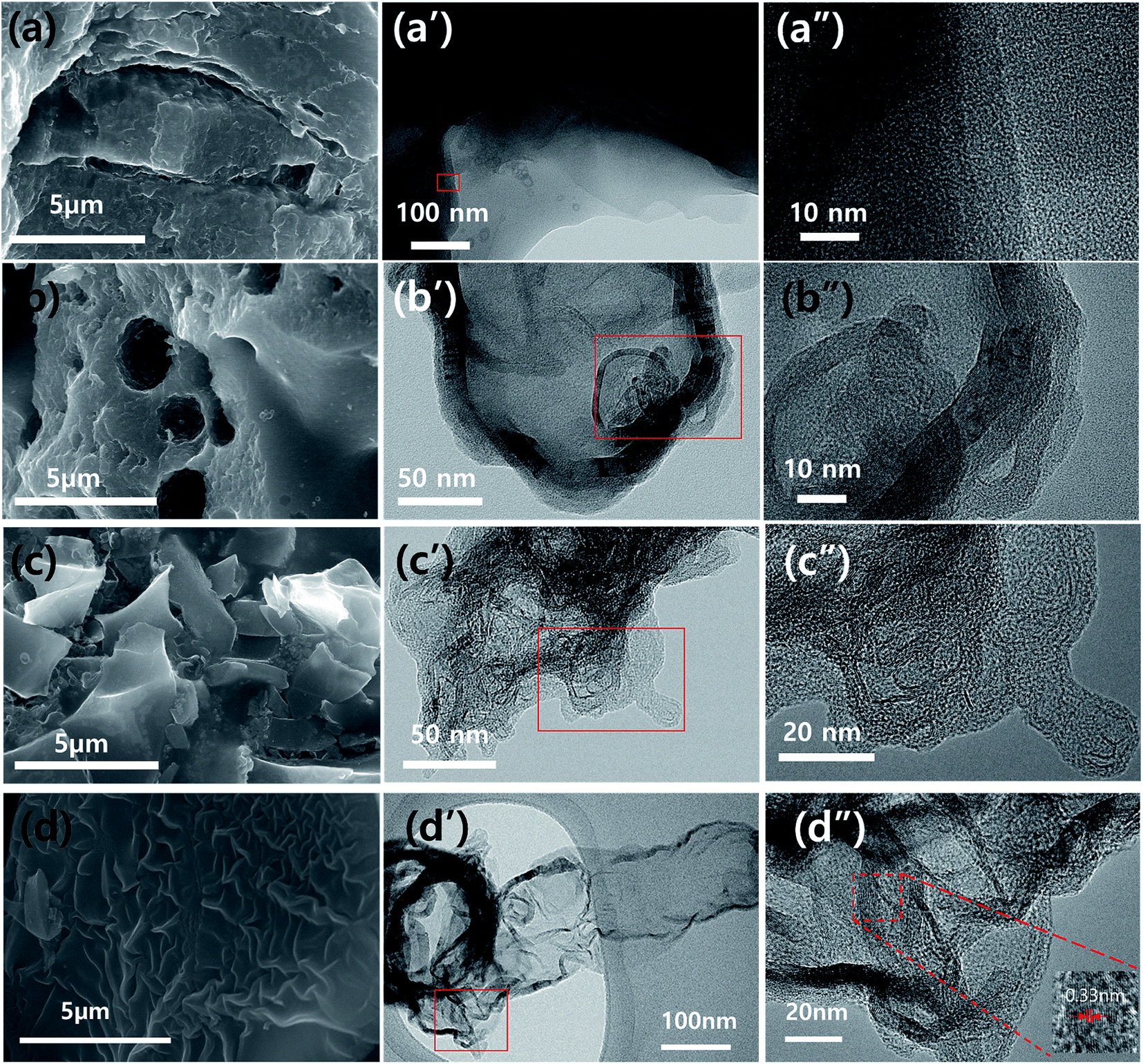 | ||
| Fig. 1 SEM ((a) to (d)) and TEM images ((a′) to (d′) and (a′′) to (d′′)) of carbonaceous materials obtained by different mass ratios of NaOH and PVP. (a) PNC, (b) PANC-1, (c) PANC-2, and (d) PANC-3. | ||
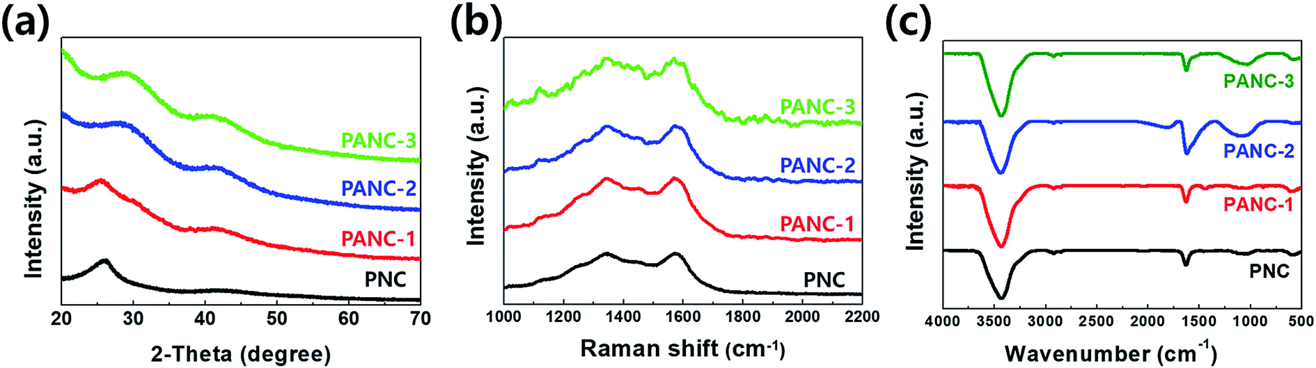 | ||
| Fig. 2 (a) XRD pattern, (b) Raman spectra, (c) FT-IR spectra of PNC, PANC-1, PANC-2, PANC-3. | ||
To investigate the porosity characterization, the nitrogen adsorption–desorption isotherms were performed to each sample. Fig. 3a exhibits the characterizations of the developed porous structures for samples. While PNC and PANC-1 show no or less adsorption at low relative pressure (P/P0 ≈ 0) indicative of the existence of micropores, the N2 adsorption in PANC-2 and PANC-3 is elevated very sharply at the same point, proving micropore development by increasing NaOH activation agent. In addition, to a non-plateau near the 1.0 of P/P0, the gradual increase of the adsorption amount of PANC-1, PANC-2, and PANC-3 demonstrates the presence of mesopores. The hysteresis loops of PANC-2 and PANC-3 exhibit H-4 adsorption isotherms, indicating the micro-, mesopores with the hierarchical structure of samples.27 The pore size distributions calculated by BJH analysis were exhibited in Fig. 3b, and detail of the specific surface area and pore volume were listed in Table 1. The BET specific surface area of the PANC-3 reaches a maximum of ca. 2400 m2 g−1 compared with that of other samples. This value is much higher than ∼1000 m2 g−1 for activated carbons prepared by conventional vapor activation. The pore size distribution curves (Fig. 3b) indicate that the PANC-2 and PANC-3 have well-developed micro-mesopores (1.6–10 nm), which become a larger when the amount of NaOH active agent increases.
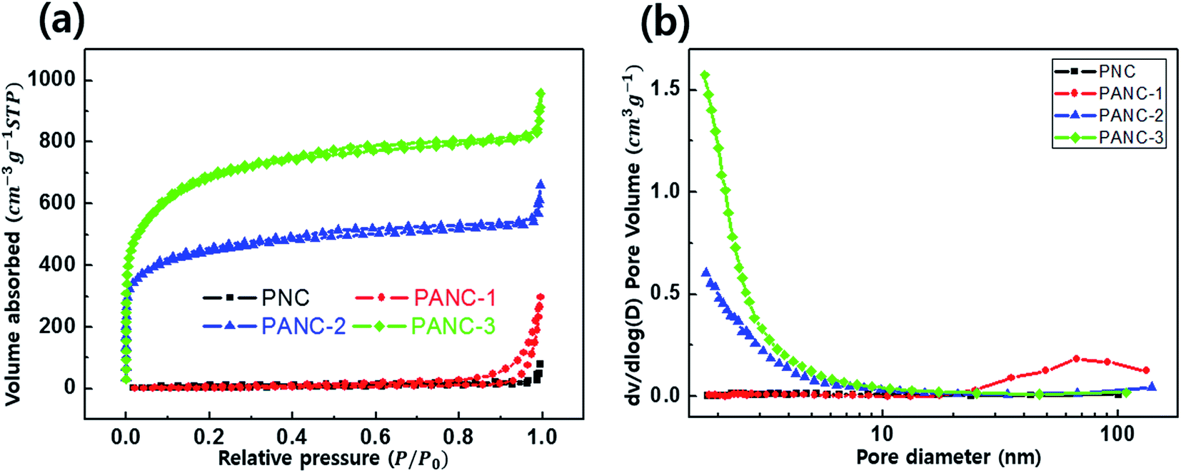 | ||
| Fig. 3 Nitrogen adsorption–desorption isotherms (a) and pore size distribution (b) of nitrogen doped porous carbon. | ||
| Sample | Nitrogen peak in XPS | SBET (m2 g−1) | Vtotal (cm3 g−1) | Vmicro (cm3 g−1) | |||
|---|---|---|---|---|---|---|---|
| Contents (wt%) | Fitting area of N (%) | ||||||
| N-6 | N-5 | N-Q | |||||
| PNC | 5.1 | 40.54 | 35.35 | 24.11 | 15.58 | 0.04 | — |
| PANC-1 | 4.49 | 36.73 | 40.02 | 23.25 | 18.72 | 0.30 | — |
| PANC-2 | 2.88 | 33.31 | 45.27 | 21.42 | 1496.26 | 0.96 | 0.53 |
| PANC-3 | 1.6 | 34.54 | 51.09 | 17.71 | 2400.05 | 1.55 | 0.82 |
The high specific surface area and the well-developed micro–mesopore structure of the sample are consistent with improving its specific capacitance because the specific capacitance performance of a carbon electrode material in the EDLC is related to its capability to absorb ions from the electrolyte. More specifically, the practical energy storage often takes place in the micropores and in the mesopores where the rapid mass transfer occurs from the micropores.28
XPS analysis (Fig. 4) confirms the presence of nitrogen atoms in highly porous nitrogen-doped carbon material derived from PVP polymer, in which the stable nitrogen groups remain during a NaOH activation process. Nitrogen atoms were fractionated within three different environments in the carbons: pyridinic (398.7 eV) N-6, pyrrolic/pyridine (400.4 eV) N-5 and quaternary (401.4 eV) N-Q.29–31 As shown in Fig. 4, various nitrogen-contained functional groups were indexed from all samples because the carbonization was carried out at a relatively low temperature (600 °C).20,32 Among the nitrogen-functional groups, N-5 and N-6 groups are generally located at the edge of carbon matrix. They can occur to the effect of pseudo-capacitance with the surface polarization of the N-doped carbon material due to the lone pair of a nitrogen atom.33 In Table 1, the pyrrolic structure (N-5) of the nitrogen bonds was dominant as the mass ratio of NaOH to PVP increased, while the nitrogen content was gradually decreased. The nitrogen contents evaluated from the XPS are 5.1, 4.49, 2.88 and 1.6 wt% in PNC, PANC-1, PANC-2 and PANC-3, respectively. It is indicated that the additive NaOH can act as a pyrolysis agent quickly to decompose PVP polymers by attacking oxygen and nitrogen atoms and to make a highly porous nitrogen-doped carbonaceous material. Although the nitrogen doping contents decrease depending on increasing the amount of NaOH, the folded few-layered graphitic carbon parts and a number of micro–mesopores were formed to help improve the electrochemical properties as shown in TEM images and BET graphs.
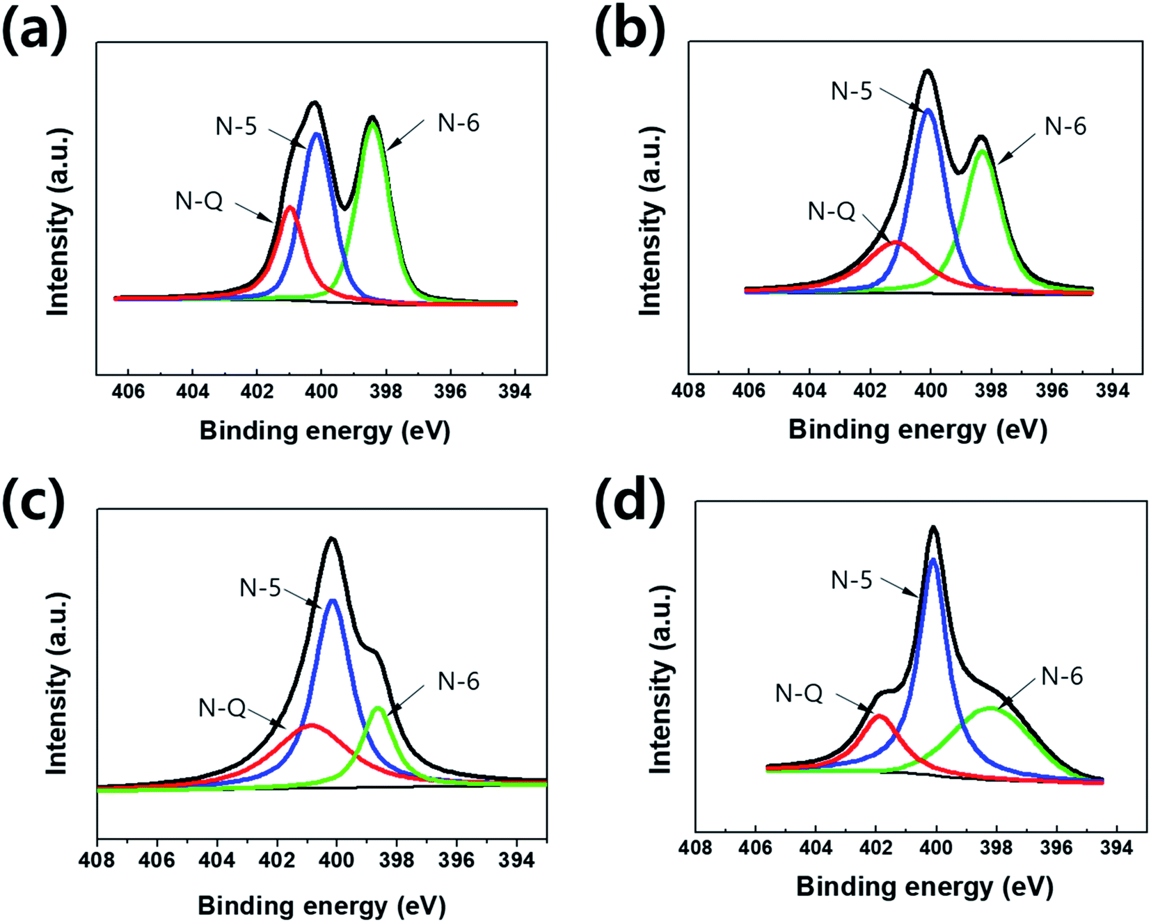 | ||
| Fig. 4 XPS spectra of the deconvoluted N 1s peak without NaOH (a) and etched samples (b–d). | ||
The electrochemical performances of the highly porous nitrogen-doped carbon materials were performed in 6 M KOH aqueous electrolytes with three-electrode system. Fig. 5a exhibits cyclic voltammograms of the electrodes at potential windows of −1 to 0 V at a scan rate of 5 mV s−1. The current range and area under the CV curves were widen with increasing the ratio of NaOH to PVP as carbon and nitrogen sources due to more evolved porous carbon structure with nitrogen functional groups. The cyclic voltammogram shows a quasi-rectangular shapes with a little redox humps indicating capacitive response contributed by both EDLC and pseudo-capacitance which was offered by the doped nitrogen. It can be considered that the balance of specific surface area and nitrogen contents is key factor for high capacitance in the nitrogen-doped porous carbons. Galvanostatic charge/discharge tests between −1 and 0 V were performed to estimate the electrochemical properties of the samples (PNC to PANC-3). The curves exhibit overall triangular shapes but, at the discharge curves, it seemed like a slightly bowed line contributed by the faradaic reactions related with CV curves. The specific capacitance of all samples calculated at a current density of 1 A g−1 from the discharge curves. The specific capacitance of PANC-3 electrode was achieved at ca. 478 F g−1 of which is overwhelming value comparing with other nitrogen doped carbon materials studied earlier (Table 2). The capacitance retention was investigated at various current densities in order to measure the rate capability of all samples (Fig. 5d). The PANC-3 electrode has the highest performances and the smallest IR-drop due to the lowest resistance confirmed in an electrochemical impedance spectroscopy (EIS) test. EIS was carried out to clarify the kinetic properties of the electrode materials. Fig. 5c presents the Nyquist plots between imaginary part (Z′′) of impedance and real part (Z′) in the variable frequency responses (0.01 to 100000 Hz) of the electrode/electrolyte. In accordance with CV and GCD, it was exhibited smaller semicircles at high frequency, almost 45° diagonal line at intermediate frequency, and nearly vertical line at low frequency. The results of the EIS curves of activated carbon samples (PANC-1 to PANC-3) show the lower resistances of charge transfer and ion diffusion and better capacitive property, comparing those of PNC with non-etched carbon.
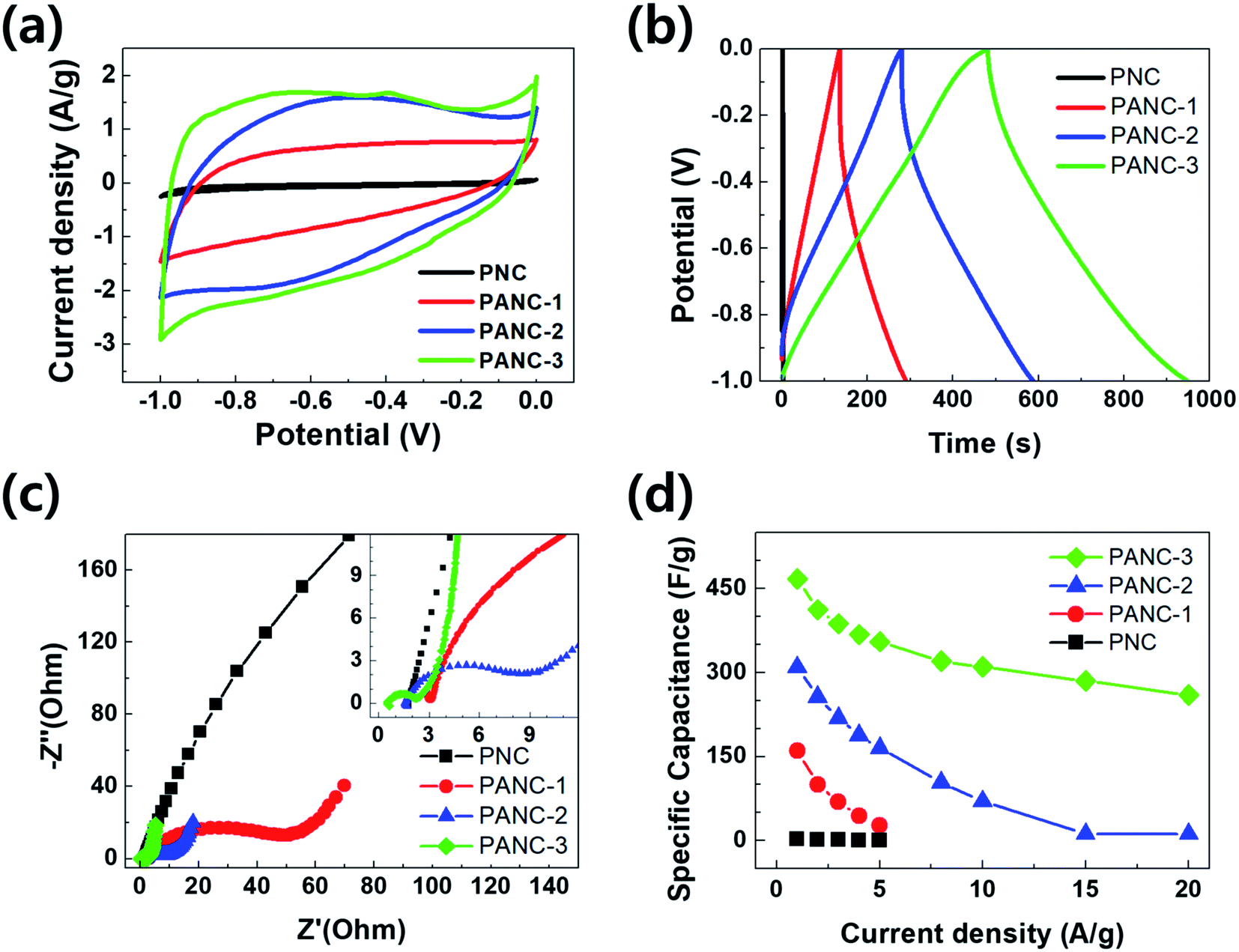 | ||
| Fig. 5 Electrochemical capacitive performance of the PVP-based activated carbon. (a) Cyclic voltammetry at 5 mV s−1, (b) galvanostatic charge/discharge curves at 1 A g−1, (c) Nyquist plots, (d) the specific capacitance as a function of current density (1–20 A g−1). | ||
| Sample | C (F g−1) | Current density | Energy density (W h kg−1) | Power density (W kg−1) | Cycle retention | Cycle number | Ref. |
|---|---|---|---|---|---|---|---|
| N-Doped mesoporous carbon thin film | 316 | 0.5 | — | — | 92.9 | 11000 |
5 |
| Hollow, spherical nitrogen rich porous carbon | 230 | 0.5 | — | — | 98 | 1500 | 21 |
| N-Doped nanosphere | 432 | 1 | 4–9.2 | 110–23240 |
∼92 | 10000 |
29 |
| N-Hierarchical porous carbon microsphere | 278 | 0.1 | — | — | 108 | 5000 | 31 |
| N-Doped porous graphitic carbon | 293 | 1 | 8.1–9.58 | 500–10500 |
99.6 | 5000 | 33 |
| N-Doped carbon nanofibers | 307.2 | 1 | 6.72–10.96 | 250–25000 |
98.2 | 10000 |
34 |
| N-Doped mesoporous carbon | 289 | 0.2 | 5–7.6 | 23–4600 | 91 | 1000 | 35 |
| N-Doped graphene | 205.3 | 0.1 | 2.8–5.5 | 450–4500 | 92.5 | 3500 | 36 |
| N-Doped porous carbons | 363 | 0.1 | — | — | 97 | 5000 | 37 |
| N-DWCNTs | 51.29 | 0.125 | 5.389–7.757 | 17–549 | — | 38 | |
| Highly porous nitrogen-doped carbons | 478 | 1 | 5.66–14.2 | 720–6035.3 | 99.9 | 10000 |
This work |
Cyclic life test of the PANC-3 (Fig. S1d†) in the three-electrode system shows outstanding capacitance retention (98.6%) as well as the high coulombic efficiency (99.6%, Fig. S2a†) after 10000 cycle at a high current density of 10 A g−1. It suggest that the electrode has high electrochemical stability and good physical durability.
To get the capacitive properties for practical application, the two-electrode system were investigated by PANC-3 electrode. The cyclic voltammetry (Fig. 6a) shows quasi-rectangular shapes as the curve in three electrode system. The specific capacitance calculated from the galvanostatic charge–discharge curves (Fig. 6b) achieved 71 F g−1 at a current density of 1 A g−1. The symmetric device shows the relatively high values compared with those of previous works (Table 2) and has the maximum energy density of 14.2 W h kg−1 with a power density of 720 W kg−1 in the Ragone plot (Fig. 6d). Along with the three-electrode test of it, the long-term durability in two-electrode system was monitored at current density of 3 A g−1. After 10000 cycle, the supercapacitor properties are expressed by the capacitance retention and coulombic efficiency that retained 99.9% and 96.1%, respectively (Fig. 6c and S2b†). Such superior capacitive performances were ascribed to the surface with the improved conductivity of partially graphitic structure and the higher porosity with nitrogen functional groups.
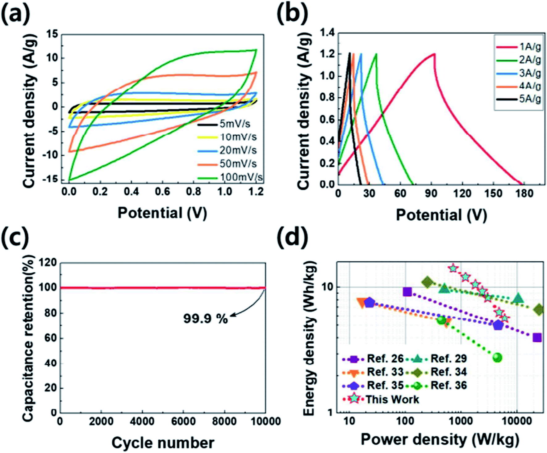 | ||
| Fig. 6 Electrochemical capacitive performance of the PANC-3 for symmetric device. (a) Cyclic voltammetry at different scan rate, (b) galvanostatic charge/discharge curves at different current density, (c) capacitance retention, (d) Ragone plot. | ||
4. Conclusions
In summary, the highly porous nitrogen doped carbon was prepared from a mixture of PVP and NaOH through the one-step process including carbonization, activation, and N-doping. And a series of carbonaceous materials were synthesized with different mass ratios of active NaOH agent and methodically characterized. The well-developed high porous carbonaceous materials comprising graphitic and amorphous structures have a very high specific surface area (Fig. S3†) up to 2400 m2 g−1, a high pore volume of 1.55 cm3 g−1 and good micro- and mesopore distribution. The synergy of highly porous structure and proper nitrogen-functional groups which generate the pseudo-capacitance maximized the electrochemical performances. The PANC-3 showed superior electrochemical performance in 6 M KOH electrolyte, such as a notable specific capacitance of 478 F g−1 at a current density of 1 A g−1, a good capacitance retention of 99.9%, and a coulombic efficiency of 96.1% for 10000 cycles. These excellent performances show the possibility of a promising material of PANC-3 as EDLC electrode material.
Conflicts of interest
There are no conflicts to declare.Acknowledgements
This work was supported by the Global Frontier R&D Program (2013M3A6B1078874) on Global Frontier Hybrid Interface Materials, funded by the Ministry of Science, ICT and Future Planning.References
- J. R. Miller and P. Simon, Science, 2008, 321, 651–652 CrossRef CAS PubMed.
- P. Simon and Y. Gogots, Nature, 2008, 7, 845–854 CrossRef CAS PubMed.
- M. Inagaki, H. Konno and O. Tanaike, J. Power Sources, 2010, 195, 7880–7903 CrossRef CAS.
- E. Frackowiak, Phys. Chem. Chem. Phys., 2007, 9, 1774–1785 RSC.
- G. Yu, X. Xie, L. Pan, Z. Bao and Y. Cui, Nano Energy, 2013, 2, 213–234 CrossRef CAS.
- D. Hulicova, J. Yamashita, Y. Soneda, H. Hatori and M. Kodama, Chem. Mater., 2005, 17, 1241–1247 CrossRef CAS.
- J. Wei, D. D. Zhou, Z. K. Sun, Y. H. Deng, Y. Y. Xia and D. Y. Zhao, Adv. Funct. Mater., 2013, 23, 2322–2328 CrossRef CAS.
- C. Vagner, G. Finqueneisel, T. Zimny, P. Burg, B. Grzyb, J. Machnikowski and J. V. Weber, Carbon, 2003, 41, 2847–2853 CrossRef CAS.
- W. Shen and W. Fan, J. Mater. Chem. A, 2013, 1, 999–1013 CAS.
- N. Kan-nari, S. Okamura, S.-I. Fujita, J.-I. Ozaki and M. Arai, Adv. Synth. Catal., 2010, 352, 1476–1484 CrossRef CAS.
- Z.-H. Sheng, L. Shao, J.-J. Chen, W.-J. Bao, F.-B. Wang and X.-H. Xia, ACS Nano, 2011, 5, 4350–4358 CrossRef CAS PubMed.
- L. Chen, T. Ji, L. Mu and J. Zhu, Carbon, 2017, 111, 839–848 CrossRef CAS.
- G. Ma, Q. Yang, K. Sun, H. Peng, F. Ran, X. Zhao and Z. Lei, Bioresour. Technol., 2015, 197, 137–142 CrossRef CAS PubMed.
- J. Zhang, Q. Li, I. S. Amiinu, H. Wu, C. Zhang, K. Cheng, H. Zhou and S. Mu, Electrochim. Acta, 2015, 177, 73–78 CrossRef CAS.
- K. Jurewicza, R. Pietrzakb, P. Nowicki and H. Wachowska, Electrochim. Acta, 2008, 53, 5469–5475 CrossRef.
- M. Yang, B. Cheng, H. Song and X. Chen, Electrochim. Acta, 2010, 55, 7021–7027 CrossRef CAS.
- D.-S. Yuan, T.-X. Zhou, S.-l. Zhou, W.-J. Zou, S.-S. Mo and N.-N. Xia, Electrochem. Commun., 2011, 13, 242–246 CrossRef CAS.
- X. Y. Chen, C. Chen, Z. J. Zhang and D. H. Xie, Ind. Eng. Chem. Res., 2013, 52, 12025–12031 CrossRef CAS.
- J. S. Lee, X. Wang, H. Luo and S. Dai, Adv. Mater., 2010, 22, 1004–1007 CrossRef CAS PubMed.
- B. Xu, S. Hou, G. Cao, F. Wu and Y. Yanga, J. Mater. Chem., 2012, 22, 19088–19093 RSC.
- Y. Zheng, Y. Jiao, M. Jaroniec, Y. Jin and S. Z. Qiao, Small, 2012, 8, 3550–3566 CrossRef CAS PubMed.
- T. C. Mendes, C. Xiao, F. Zhou, H. Li, G. P. Knowles, M. Hilder, A. Somers, P. C. Howlett and D. R. MacFarlane, ACS Appl. Mater. Interfaces, 2016, 8, 35243–35252 CAS.
- Y. Hu, H. Liu, Q. Ke and J. Wang, J. Mater. Chem. A, 2014, 2, 11753–11758 CAS.
- J. P. Paraknowitsch, J. Zhang, D. Su, A. Thomas and M. Antonietti, Adv. Mater., 2010, 22, 87–92 CrossRef CAS PubMed.
- T. Palaniselvam, H. Barike Aiyappa and S. Kurungot, J. Mater. Chem., 2012, 22, 23799–23805 RSC.
- A. Alabadi, H. A. Abbood, Q. Li, N. Jing and B. Tan, Sci. Rep., 2016, 6, 38614 CrossRef CAS PubMed.
- K. A. Cychosz, R. Guillet-Nicolas, J. García-Martínez and M. Thommes, Chem. Soc. Rev., 2017, 46, 389–414 RSC.
- X. Y. Chen, C. Chen, Z. J. Zhang, D. H. Xie, X. Deng and J. W. Liu, J. Power Sources, 2013, 230, 50–58 CrossRef CAS.
- F. Sun, J. Gao, X. Pi, L. Wang, Y. Yang, Z. Qu and S. Wu, J. Power Sources, 2017, 337, 189–196 CrossRef CAS.
- M.-Y. Zhang, X.-J. Jin and Q. Zhao, New Carbon Mater., 2014, 29, 89–95 CrossRef CAS.
- J. Jiang, H. Chen, Z. Wang, L. Bao, Y. Qiang, S. Guan and J. Chen, J. Colloid Interface Sci., 2015, 452, 54–61 CrossRef CAS PubMed.
- J. Ji, J. Liu, L. Lai, X. Zhao, Y. Zhen, J. Lin, Y. Zhu, H. Ji, L. L. Zhang and R. S. Ruoff, ACS Nano, 2015, 9, 8609–8616 CrossRef CAS PubMed.
- L. Sun, C. Tian, Y. Fu, Y. Yang, J. Yin, L. Wang and H. Fu, Chem.–Eur. J., 2014, 20, 564–574 CrossRef CAS PubMed.
- L.-F. Chen, Y. Lu, L. Yu and X. Wen Lou, Energy Environ. Sci., 2017, 1777–1783 CAS.
- M. Li and J. Xue, J. Phys. Chem. C, 2014, 118, 2507–2517 CAS.
- Y.-Z. Liu, Y.-F. Li, F.-Y. Su, L.-J. Xie, Q.-Q. Kong, X.-M. Li, J.-G. Gao and C.-M. Chen, Energy Storage Materials, 2016, 2, 69–75 CrossRef.
- M. Zhou, F. Pu, Z. Wang and S. Guan, Carbon, 2014, 68, 185–194 CrossRef CAS.
- V. Thirumal, A. Pandurangan, R. Jayavel, S. R. Krishnamoorthi and R. Ilangovan, Curr. Appl. Phys., 2016, 16, 816–825 CrossRef.
Footnote |
| † Electronic supplementary information (ESI) available. See DOI: 10.1039/c7ra09272e |
| This journal is © The Royal Society of Chemistry 2017 |