 Open Access Article
Creative Commons Attribution 3.0 Unported Licence
Facile synthesis of hierarchical nanocomposites of aligned polyaniline nanorods on reduced graphene oxide nanosheets for microwave absorbing materials
Yuefang Zhangab,
Jia Liua,
Yahong Zhanga,
Jin Liua and
Yuping Duan *a
*a
aKey Laboratory of Solidification Control and Digital Preparation Technology (Liaoning Province), School of Materials Science and Engineering, Dalian University of Technology, Dalian 116085, P. R. China. E-mail: duanyp@dlut.edu.cn; Fax: +86 411 84708446; Tel: +86 411 84708446
bSchool of Materials Science and Chemical Engineering, Hainan University, Haikou, 570228, China
First published on 24th November 2017
Abstract
A facile in situ polymerization process was introduced for the preparation of RGO–PANI hybrids with investigation of their microwave absorbing properties. The structural and morphological characterization were performed using Fourier transform infrared (FTIR), X-ray diffraction (XRD), Raman spectroscopy, scanning electron microscopy (SEM) and transmission electron microscopy (TEM). The results indicated that the hierarchical nanocomposites of aligned polyaniline nanorods grown vertically on the surface of RGO were successfully synthesized. The hybrids with special structure possessed more distinct dielectric response characteristics and better electromagnetic absorption properties than pure PANI. The maximum reflection loss value of the composites is up to −43 dB at 12.4 GHz and the absorption bandwidth exceeding −10 dB is 3.5 GHz with a thickness of 2 mm. The results indicate that hierarchical nanocomposites of aligned polyaniline nanorods on reduced graphene oxide nanosheets are efficient materials for microwave absorption.
1. Introduction
With the extensive utilization of electronic devices and communication facilities in the GHz frequency range, the corresponding problems of electromagnetic (EM) interference and radiation pollution have become extra prominent. Moreover, electromagnetic waves can weaken biological immune systems, and significantly threaten human health.1–3 To prevent and restrain these hazards, the demands for developing electromagnetic wave absorbers with broader absorbing bandwidths and more effective absorption properties is ever urgent which has aroused the intense interest of researchers.4,5Graphene, a flat monolayer of hexagonally arrayed sp2-bonded carbon atoms tightly packed into a two-dimensional (2D) honeycomb lattice, has attracted tremendous scientific attention due to its promise in the field of microwave-absorbent materials.6,7 Furthermore, reduced graphene oxide (RGO) coupled with clustered defects and functional groups has the properties of graphene while being easier to fabricate. RGO materials possess a good electrical conductivity and high surface area, thus holding great promise for microwave absorbing applications. Wen et al.8 compared RGO with graphite nanosheets (GN), reporting that the increased polarization ability and high conductivity endowed the RGO composites exhibit higher dielectric properties and enhanced microwave attenuation performances. However, due to the agglomeration effects and poor impedance matching of pristine RGO sheets, the microwave absorption efficiency of RGO is still limited. Therefore, incorporation of other doping materials has been widely studied as an imperative solution to improve microwave absorption properties for RGO materials.
Conducting polymers have been extensively studied as microwave absorbing materials, such as polypyrrole,9,10 PEDOT,11 PVDF,12 and so on. Among these, polyaniline (PANI) is considered to be one of the most promising conducting polymers that is low cost, environmentally stable, relatively high conductivity and can be used as microwave absorption materials.13–15 However, a relatively high permittivity and quite low permeability of PANI materials always present unsatisfactory impedance matching, which deviates from the zero-reflection condition at the surface of the materials,16 resulting in weak microwave absorption properties. In order to avoid the drawback of single material, researchers have been focused on studies of synergistic composite materials. Ting et al.17 reported an in situ polymerization process to synthesize PANI/MWNT composites and subsequent research suggested that the addition of MWNT was useful for achieving a large absorption over a wide frequency range, especially for higher frequency values. Chen and co-workers18 prepared graphene/PANI hybrids through a new approach and discussed the microwave absorption properties. They demonstrated that there were special interactions between PANI and graphene molecules, which contributed to conductivity and permittivity of the composites. The results show that the minimum reflection loss was −36.9 dB with a thickness of 3.5 mm and the bandwidth corresponding to the reflection loss at −10 dB was 5.3 GHz. While many researchers have concentrated on the microwave absorption performance of doping PANI composites, there are few papers on the microwave absorption properties of PANI covered on the surface of RGO.
Herein, we directly grow PANI nanorods on the surface of RGO by an in situ polymerization process. The mechanism for the formation of hierarchical RGO–PANI nanocomposites was investigated in detail. The microwave dielectric response and the corresponding electromagnetic properties of the RGO–PANI composites were investigated, as well as how the above features are influenced by the doping ratios of aniline. The results demonstrate that RGO–PANI is an efficient candidate for microwave absorption.
2. Experimental section
2.1 Sample preparation
The raw material, graphene oxide (GO) ethanol solution (5.7 mg mL−1), was purchased from Institute of coal chemistry, CAS. The RGO sheets used in this work were reduced from GO with hydrazine hydrate using the Wallace method. PANI–RGO composites were chemically synthesized by oxidative polymerization of aniline using ammonium peroxydisulfate (APS) under controlled conditions. In detail, 15 mL GO was dissolved in 30 mL ethanol solution and ultrasonicated for 1 h to form a homogeneous dispersion. Then 0.1 mL hydrazine monohydrate was added and heated to 60 °C for 12 h. After that, aniline monomer dissolved in 50 mL 1 mol L−1 HCl aqueous solution were added into the above solution and stirred for 30 min at 0 °C. The oxide, APS (the mole ratio of APS![[thin space (1/6-em)]](https://www.rsc.org/images/entities/char_2009.gif) :
:![[thin space (1/6-em)]](https://www.rsc.org/images/entities/char_2009.gif) aniline = 1.2
aniline = 1.2![[thin space (1/6-em)]](https://www.rsc.org/images/entities/char_2009.gif) :
:![[thin space (1/6-em)]](https://www.rsc.org/images/entities/char_2009.gif) 1) dissolved in 50 mL 1 mol L−1 HCl was slowly dripped into the above-mentioned mixture. The reaction beaker was placed in an ice bath (to maintain a reaction temperature of 0–3 °C) for 1 h with stirring, and then refrigerated for 12 h. Finally, the precipitate was washed by distilled water and ethanol for three times and then dried at 40 °C for 12 h. At a constant concentration of GO (0.59 mg mL−1), the concentration of aniline was changed as 0.04, 0.07 and 0.1 mol L−1, and the obtained composites were named as PRG 1, PRG 2 and PRG 3, respectively. For comparison, the pure PANI was synthesized chemically at 0.07 mol L−1 aniline in the absence of graphene oxide.
1) dissolved in 50 mL 1 mol L−1 HCl was slowly dripped into the above-mentioned mixture. The reaction beaker was placed in an ice bath (to maintain a reaction temperature of 0–3 °C) for 1 h with stirring, and then refrigerated for 12 h. Finally, the precipitate was washed by distilled water and ethanol for three times and then dried at 40 °C for 12 h. At a constant concentration of GO (0.59 mg mL−1), the concentration of aniline was changed as 0.04, 0.07 and 0.1 mol L−1, and the obtained composites were named as PRG 1, PRG 2 and PRG 3, respectively. For comparison, the pure PANI was synthesized chemically at 0.07 mol L−1 aniline in the absence of graphene oxide.
2.2 Characterization
Scanning electron microscope (SEM) and transmission electron microscope (TEM) images were obtained with a SUPRA55 (Zeiss) and a Tecnai G220 S-Twin (FEI), respectively. The crystal structures of the samples were determined by X-ray diffraction (SHIMADZU, XRD-6000) analyses equipped with Cu Kα radiation source. The scanning range was from 5.00° to 80.00° and the scan speed was 4.00° min−1. Raman spectra were obtained using a Laser Raman spectroscopy (Invia, RENISHAW) using a 514 nm argon ion laser. Fourier transform infrared (FTIR) spectra of the samples were recorded on a Bruker Vertex-70 FTIR spectrometer.For electromagnetic properties, an Aglient 8722ES vector network analyzer was applied to determine the relative permeability and permittivity in the frequency range of 2–18 GHz. The composites were homogeneously mixed with 75 wt% molten paraffin and the mixture were pressed into toroidal shaped samples (φout: 7.00 mm; φin: 3.00 mm). Transmission line theory was introduced to calculate the microwave absorption properties, which is appointed as reflection loss (RL).
3. Results and discussion
3.1 Structure characterization
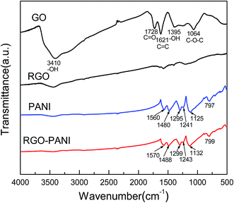
Fig. 1 shows the FT-IR spectra of GO, RGO, PANI and RGO–PANI composites. The typical FT-IR spectrum of GO is an agreement with previous work.19,20 The bands at 3410, 1728, 1621, 1395, and 1064 cm−1 correspond to –OH in intercalated water, C![[double bond, length as m-dash]](https://www.rsc.org/images/entities/char_e001.gif) O in COOH, C
O in COOH, C![[double bond, length as m-dash]](https://www.rsc.org/images/entities/char_e001.gif) C, –OH in C–OH and C–O in COC(epoxy) functional groups, respectively. These features indicate that graphene oxide is heavily oxidized and contains large quantity of oxygen containing functional groups. Compared with GO, the featureless spectra of RGO indicates that the chemical reduction of GO is relatively complete. For PANI, the appearance of peaks at 1560 and 1480 cm−1 are attributed to the C
C, –OH in C–OH and C–O in COC(epoxy) functional groups, respectively. These features indicate that graphene oxide is heavily oxidized and contains large quantity of oxygen containing functional groups. Compared with GO, the featureless spectra of RGO indicates that the chemical reduction of GO is relatively complete. For PANI, the appearance of peaks at 1560 and 1480 cm−1 are attributed to the C![[double bond, length as m-dash]](https://www.rsc.org/images/entities/char_e001.gif) C stretching of the quinonoid and benzenoid rings, respectively.21 Meanwhile, the bands at 1295, 1241 and 1125 cm−1 are ascribed to C–N and C–H bending of benzenoid and quinoid rings. These are characteristics absorption bands of PANI, confirming the successful synthesis of PANI. The FTIR spectrum of RGO–PANI is almost the same as PANI which confirms the successful coating of PANI nanorods. It is worth mentioning here that the peaks related to the PANI matrix in the RGO–PANI composites shift to higher wavenumbers. These shifts may arise from π–π interaction and hydrogen bonding between RGO sheets and the polymer backbone.
C stretching of the quinonoid and benzenoid rings, respectively.21 Meanwhile, the bands at 1295, 1241 and 1125 cm−1 are ascribed to C–N and C–H bending of benzenoid and quinoid rings. These are characteristics absorption bands of PANI, confirming the successful synthesis of PANI. The FTIR spectrum of RGO–PANI is almost the same as PANI which confirms the successful coating of PANI nanorods. It is worth mentioning here that the peaks related to the PANI matrix in the RGO–PANI composites shift to higher wavenumbers. These shifts may arise from π–π interaction and hydrogen bonding between RGO sheets and the polymer backbone.
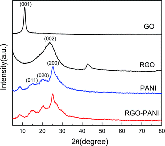
The structure of the composites was further investigated by powder X-ray diffraction (XRD) analysis (Fig. 2). A strong characteristic peak of GO is observed at 2θ of 11.2°, indicating an increase in the interlayer distance caused by the introduction of oxygen containing groups compared with typical graphite. After chemical reduction, a broader peak of RGO caused by the disorder in the graphene sheets appears at 23.76°, illustrating that most oxygen functional groups have been removed from the GO surface.22 The pure PANI exhibits one sharp peak centered around 25.3° accompanied by other two low intensity peaks with their position around 20° and 15.2°, corresponding to (200), (020), and (011) semi-crystalline planes of PANI in its emeraldine salt (ES) form, respectively.23 For RGO–PANI composites, the characteristic peaks are almost the same as that of pure PANI, which confirmed that the formation of PANI nanoparticle is sufficient to coat on the surface of the RGO sheets.
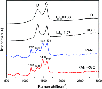
Raman spectroscopy is one of the most suitable tools to characterize carbon materials. Fig. 3 shows the Raman spectra of GO, RGO, PANI and PANI–RGO nanocomposites. Both GO and RGO display two prominent Raman-active peaks at 1350 cm−1 assigned to the D mode corresponding to the structural defects and at 1590 cm−1 corresponding to the G mode related to the first-order scattering of the E2g mode observed for sp2-carbon domains.24 In addition, the intensity ratio (ID/IG) of RGO (1.07) increases more than that of GO (0.88), indicating that many defects are formed and a high level of disorder is introduced during the reduction process, which is consistent with previous XRD and FT-IR data. For PANI–RGO composites, C–H bending deformation in the benzenoid ring at 1162 cm−1, C–N+ stretching at 1335 cm−1, C![[double bond, length as m-dash]](https://www.rsc.org/images/entities/char_e001.gif) N stretching vibration at 1480 cm−1, C
N stretching vibration at 1480 cm−1, C![[double bond, length as m-dash]](https://www.rsc.org/images/entities/char_e001.gif) C stretching of quinoid at 1595 cm−1 are observed, revealing the presence of PANI structure on the surface of RGO.25 The Raman spectrum of PANI–RGO is very similar to pure PANI except some slight redshifts, because the pure PANI possesses the similar Raman features when combined with carbon structure. Furthermore, low content of RGO in this hybrids is another important factor. It is also worth noting that the PANI–RGO composite presents an increased intensity of C
C stretching of quinoid at 1595 cm−1 are observed, revealing the presence of PANI structure on the surface of RGO.25 The Raman spectrum of PANI–RGO is very similar to pure PANI except some slight redshifts, because the pure PANI possesses the similar Raman features when combined with carbon structure. Furthermore, low content of RGO in this hybrids is another important factor. It is also worth noting that the PANI–RGO composite presents an increased intensity of C![[double bond, length as m-dash]](https://www.rsc.org/images/entities/char_e001.gif) N stretching and a shift towards low wavenumbers as compared to PANI, which owing to the strong π–π electronic interaction between RGO and PANI.
N stretching and a shift towards low wavenumbers as compared to PANI, which owing to the strong π–π electronic interaction between RGO and PANI.
3.2 Microstructure and morphologies
The morphology and structure of the samples are shown in Fig. 4. It can be found that the samples of pure PANI in Fig. 4(a) are fully composed of well dispersed nanofiber, whose size is about 350 nm in length and 70 nm in diameter. The reduced graphene oxide prepared here has typically transparent lamellar structure with the size of hundreds of nanometers, as shown in Fig. 4(b). For PANI–RGO composites, Fig. 4(c) shows that PANI nanofiber arrays were vertically aligned on the surface of RGO evenly. Compared with random disperse states, the size of well-ordered PANI in the composites became much smaller (about 20 nm). Transmission electron microscopy (TEM) was further used to confirm the hierarchical morphology of composites. From TEM image in Fig. 4(d), some wrinkled forms uniformly distributed on the surface of RGO were clearly shown.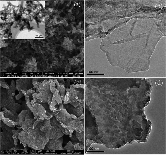 | ||
| Fig. 4 SEM image of pure PANI (inset exhibits TEM image of pure PANI) (a); TEM of reduced GO (b); SEM (c) and TEM (d) of PANI–RGO composites. | ||
RGO has two-dimensional sheets that have many defects and various oxygen functional groups on their edges. These regions could act as anchor sites and enable the subsequent in situ polymerization of PANI attaching on the surfaces and edges of RGO sheets.26 In addition, the π–π stacking force and hydrogen bonding between the phenyl and basal plane of RGO were also beneficial to nucleation and growth processes of PANI occurred on the surface of RGO.
3.3 Electromagnetic properties
The real permittivity (ε′) and imaginary permittivity (ε′′) of the samples with different concentration of aniline were investigated in the frequency range of 2–18 GHz, as shown in Fig. 5. Generally, the real parts of complex permittivity and permeability represent the storage capability of electric and magnetic energy, and the imaginary parts represent the loss of electric and magnetic energy.27,28 From the Fig. 5(a), it is clear that the real parts (ε′) of the four samples show a declining tendency with increasing frequency, which is demonstrated as dielectric dispersion. The real parts ε′′ increased firstly and then decreased with the concentration of aniline increasing. And PRG 2 shows more distinct dielectric response characteristics than other samples, which may be closely related to permutation intensity of aligned polyaniline nanorods at the microscopic scale. The permittivity is an expression of the polarization of a material and consists of interface and dipole relaxation polarization process under the EM field.29 When an external EM field is applied to the composite, the random dipoles of the composites will change their orientation to be parallel to the external field, leading to dipole polarization.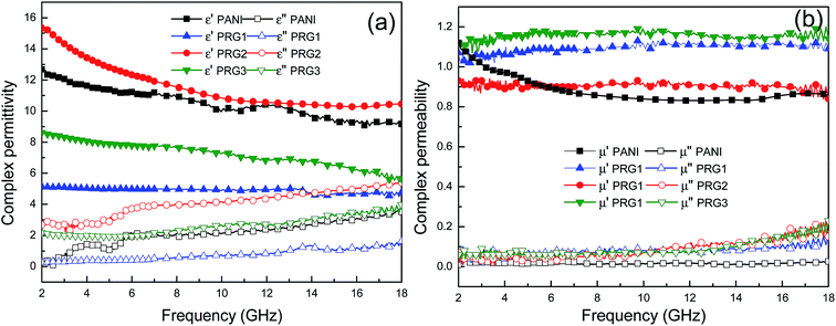 | ||
| Fig. 5 Frequency dependence of relative complex permittivity real part and imaginary part (a); frequency dependence of relative complex permeability real part and imaginary part (b). | ||
However, in practice, there is much resistance to overcome during the energy loss process. When the frequency increases to a certain degree, the rearrangement of the dipoles is unable to keep pace with the rapid changing the external field and makes virtually no contribution to the dielectric polarization. Therefore, the dielectric response tends to gradually decrease with increasing frequency as shown in Fig. 5(a). The imaginary parts (ε′′) of PANI and PANI–RGO composites have a strong dependence of the content of PANI, which are found to increase when the frequency increases in the tested region. The 0.07 mol L−1 aniline sample (PRG 2) shows relatively higher ε′′ values than the other samples in the whole frequency range of 2–18 GHz, which can result in excellent dielectric loss properties. As is shown in Fig. 5(b), the permeability real part (μ′) and imaginary part (μ′′) are almost constant with no obvious variation in the whole frequency range. In particular, their imaginary parts are very close to zero, implying their negligible magnetic loss.
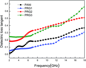
The dielectric loss tangent (tan![[thin space (1/6-em)]](https://www.rsc.org/images/entities/char_2009.gif) δE = ε′′/ε′) represents the material's conversion of microwave radiation into other energy forms. In theory, the higher dielectric loss tangent, the more EM wave energy gets absorbed.30,31 As shown in Fig. 6, the dielectric loss tangent values of the four samples increased with the increasing frequency, and the samples of PRG 2 and PRG 3 show larger tan
δE = ε′′/ε′) represents the material's conversion of microwave radiation into other energy forms. In theory, the higher dielectric loss tangent, the more EM wave energy gets absorbed.30,31 As shown in Fig. 6, the dielectric loss tangent values of the four samples increased with the increasing frequency, and the samples of PRG 2 and PRG 3 show larger tan![[thin space (1/6-em)]](https://www.rsc.org/images/entities/char_2009.gif) δE than that of PANI within the entire frequency range. However, the tan
δE than that of PANI within the entire frequency range. However, the tan![[thin space (1/6-em)]](https://www.rsc.org/images/entities/char_2009.gif) δE is reduced when the loading aniline is decreased to 0.04 mol L−1 (PRG 1), which indicates lower energy loss capabilities. This is because RGO layers cannot be completely covered by aligned PANI nanofiber arrays in the case of excessively low concentration of aniline, resulting in no chemical reaction “empty RGO” region. The incomplete structure will affect the construction of the conductive network, reducing the electron transition effect and interfacial polarization effect, thus affecting the dielectric loss properties. Nevertheless, it can be concluded that the dielectric loss in the composite is significantly enhanced by doping RGO with PANI, especially when the concentrate of aniline is 0.07 and 0.1 M.
δE is reduced when the loading aniline is decreased to 0.04 mol L−1 (PRG 1), which indicates lower energy loss capabilities. This is because RGO layers cannot be completely covered by aligned PANI nanofiber arrays in the case of excessively low concentration of aniline, resulting in no chemical reaction “empty RGO” region. The incomplete structure will affect the construction of the conductive network, reducing the electron transition effect and interfacial polarization effect, thus affecting the dielectric loss properties. Nevertheless, it can be concluded that the dielectric loss in the composite is significantly enhanced by doping RGO with PANI, especially when the concentrate of aniline is 0.07 and 0.1 M.
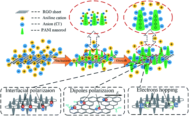
On the basis of the above experimental results, a possible mechanism for the formation of RGO–PANI hybrids and dielectric loss was schematically proposed in Fig. 7. After adding aniline into the mixed suspension of HCl and RGO, aniline cations would be first formed and immediately adsorbed on the surface of RGO owing to electrostatic attraction. When the oxidant and initiator APS was added, polymerization occurred just at the adsorbing sites, and thus a large number of PANI nuclei are generated on the RGO surface at the starting-period of the polymerization process by heterogeneous nucleation. The initial low molecular weight PANI was positively charged, so the free negative ions (Cl−) in the solution would spontaneously gather surround the PANI molecular chains, forming a very fine protective layer to restrain the growth of PANI. This explains the PANI nanowires size decreases when doping with RGO nanosheets. There are three main ways to consume electromagnetic energy loss for RGO–PANI composites with special structure: interfacial polarization, dipole polarization and electrons hopping effects. In the range of microwave frequency, interfacial polarization and dipole polarization play a major role. Firstly, growing aligned polyaniline nanorods on reduced graphene oxide nanosheet results in numerous interfaces associated with enhanced dielectric relaxation,32 and the interfacial polarized electron/ion will generate the orientation change and release heat, which facilitate the improvement of EM wave absorption properties. Secondly, as a result of the defects, the dipoles exist on the surface of RGO, which can give rise to orientation polarization in the presence of an alternate electromagnetic field to dissipate a certain amount of electromagnetic waves in the form of heat.
3.4 Microwave absorbing properties
To reveal the microwave absorption performance of synthesized RGO–PANI composites, the reflection loss (RL) values were calculated using the relative complex permeability and permittivity at a given layer thickness according to the transmission line theory, which is backed by a perfect conductor for single absorber layer, as follows:
 | (1) |
 | (2) |
 | (3) |
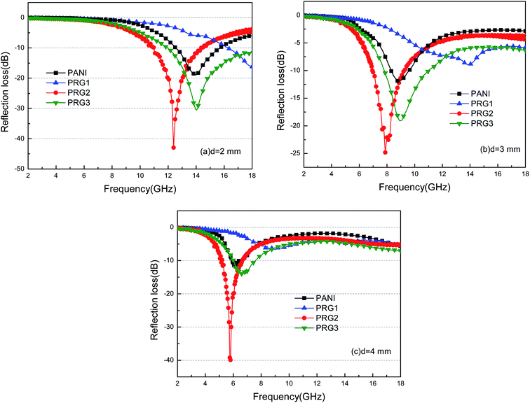 | ||
| Fig. 8 The calculated reflection losses for PANI and RGO–PANI composite samples with d = 2 mm (a), 3 mm (b) and 4 mm (c) in the frequency range of 2–18 GHz. | ||
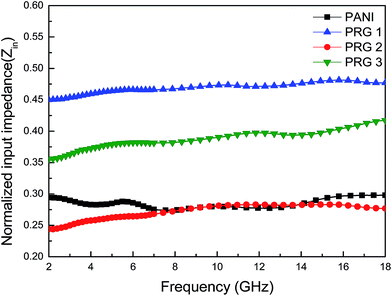
It can be seen that the maximum RL of PANI is only −18 dB at 13.8 GHz with a thickness of 2 mm. This demonstrates that PANI fibers exhibits a relatively weak ability to absorb EM wave. However, as shown in Fig. 8(a), after PANI nanorods are grown on the surface of RGO, the maximum RL of the composites (PRG 2) increases to −43 dB at 12.4 GHz and the absorption bandwidths exceeding −10 dB are 3.5 GHz (from 10.9 GHz to 14.4 GHz) with a thickness 2 mm. The results demonstrate that RGO–PANI nanorods possess excellent microwave absorption capabilities, in terms of both maximum RL value and absorption bandwidths. Generally, apart from dielectric loss, another important concept relating to excellent microwave absorption is strongly dependent on the impedance matching. According to eqn (1) and (2), Zin (Zin equals real input impedance divided by impedance in free space (377 Ω sq−1)) should be close to 1.0 to achieve lower reflection of microwave. From Fig. 9, it is clear that the values of Zin for PRG 1 are the maximal and most close to 1.0, indicating a better impedance matching. While the values of PRG 2 are farthest away from 1.0, so that more EM waves are reflected off. However, in fact, the corresponding RL of PRG 1 is only −8.9 dB at 3 mm, much lower than that of PRG 2. The reason is that a better impedance matching condition only means that a small part of the EM waves are reflected at its surface, but the value of dielectric loss tangent is also a decisive effect for the effective attenuation of the entering EM wave. Therefore, to achieve excellent wave-absorbing properties, both relatively large loss tangent and impedance matching condition should be considered at the same time.35
As mentioned above, we conclude that the as-prepared RGO–PANI composites exhibit excellent EM absorption performance and the effective EM absorption frequency can be tailored by controlling the mass ratios of RGO/PANI and thickness of the absorbing material.
4. Conclusions
Aligned PANI nanofiber arrays decorated reduced graphene oxide (RGO) were synthesized via a facile in situ polymerization process. The hybrids of RGO–PANI exhibited a superior electromagnetic wave absorption performance with high efficiency and broad bandwidth at thin thicknesses. Impressively, an effective bandwidth of 3.5 GHz was observed for the 0.07 mol L−1 aniline sample (PRG2) with a thickness of 2.0 mm. The highest reflection loss of a sample with the thickness of 2.0 mm reached −43 dB at 12.4 GHz. The famous properties were mainly attributed to the compromise between the impedance matching condition and the dielectric loss. The experimental results verified the good hybridization between PANI and RGO, giving rise to the enhanced dielectric dipole polarization, interfacial polarization and electrons hopping. Thus, the deposition of PANI nanofibers on the surface of RGO is an efficient way to fabricate lightweight composites for excellent electromagnetic absorption properties.Conflicts of interest
There are no conflicts to declare.Acknowledgements
The authors acknowledge the Supported by Program for the National Natural Science Foundation of China (No. 51577021), the Fundamental Research Funds for the Central Universities (DUT17GF107), Industry-University-Research Collaboration Project of Aviation Industry Corporation of China (cxy2103DLLG34).References
- J. Z. He, X. X. Wang and Y. L. Zhang, et al., Small magnetic nanoparticles decorating reduced graphene oxides to tune the electromagnetic attenuation capacity, J. Mater. Chem. C, 2016, 4(29), 7130–7140 RSC.
- J. R. Jauchem and K. L. Ryan, Cardiovascular and thermal effects of microwave irradiation at 1 and/or 10 GHz in anesthetized rats, Bioelectromagnetics, 2000, 21(3), 159–166 CrossRef CAS PubMed.
- C. Liu, Y. Xu and L. Wu, et al., Fabrication of core–multishell MWCNT/Fe3O4/PANI/Au hybrid nanotubes with high-performance electromagnetic absorption, J. Mater. Chem. A, 2015, 3(19), 10566–10572 CAS.
- D. Yuping, W. Guangli and G. Shuchao, et al., Study on microwave absorbing properties of carbonyl–iron composite coating based on PVC and Al sheet, Appl. Surf. Sci., 2012, 258(15), 5746–5752 CrossRef.
- W. Zhu, L. Wang and R. Zhao, et al., Electromagnetic and microwave-absorbing properties of magnetic nickel ferrite nanocrystals, Nanoscale, 2011, 3(7), 2862–2864 RSC.
- Y. Zhu, S. Murali and W. Cai, et al., Graphene and graphene oxide: synthesis, properties, and applications, Adv. Mater., 2010, 22(35), 3906–3924 CrossRef CAS PubMed.
- W. Q. Cao, X. X. Wang and J. Yuan, et al., Temperature dependent microwave absorption of ultrathin graphene composites, J. Mater. Chem. C, 2015, 3(38), 10017–10022 RSC.
- B. Wen, X. X. Wang and W. Q. Cao, et al., Reduced graphene oxides: the thinnest and most lightweight materials with highly efficient microwave attenuation performances of the carbon world, Nanoscale, 2014, 6(11), 5754–5761 RSC.
- M. S. S. Dorraji, M. H. Rasoulifard and A. R. Amani-Ghadim, et al., Microwave absorption properties of polypyrrole-SrFe12O19-TiO2-epoxy resin nanocomposites: optimization using response surface methodology, Appl. Surf. Sci., 2016, 383, 9–18 CrossRef.
- J. Stejskal, M. Trchová and P. Bober, et al., Polypyrrole salts and bases: superior conductivity of nanotubes and their stability towards the loss of conductivity by deprotonation, RSC Adv., 2016, 6(91), 88382–88391 RSC.
- P. B. Liu, Y. Huang and X. Sun, Excellent electromagnetic absorption properties of poly(3, 4-ethylenedioxythiophene)-reduced graphene oxide–Co3O4 composites prepared by a hydrothermal method, ACS Appl. Mater. Interfaces, 2013, 5(23), 12355–12360 CAS.
- X. J. Zhang, G. S. Wang and W. Q. Cao, et al., Enhanced microwave absorption property of reduced graphene oxide (RGO)-MnFe2O4 nanocomposites and polyvinylidene fluoride, ACS Appl. Mater. Interfaces, 2014, 6(10), 7471–7478 CAS.
- N. G. Deshpande, Y. G. Gudage and R. Sharma, et al., Studies on tin oxide-intercalated polyaniline nanocomposite for ammonia gas sensing applications, Sens. Actuators, B, 2009, 138(1), 76–84 CrossRef CAS.
- Y. S. Negi and P. V. Adhyapak, Development in polyaniline conducting polymers, J. Macromol. Sci., Part C: Polym. Rev., 2002, 42(1), 35–53 CrossRef.
- M. Oyharçabal, T. Olinga and M. P. Foulc, et al., Influence of the morphology of polyaniline on the microwave absorption properties of epoxy polyaniline composites, Compos. Sci. Technol., 2013, 74, 107–112 CrossRef.
- K. J. Vinoy and R. M. Jha, Radar absorbing materials- From theory to design and characterization, Kluwer Academic Publishers, Boston, MA, 1996, p. 1996 Search PubMed.
- T. H. Ting, Y. N. Jau and R. P. Yu, Microwave absorbing properties of polyaniline/multi-walled carbon nanotube composites with various polyaniline contents, Appl. Surf. Sci., 2012, 258(7), 3184–3190 CrossRef CAS.
- X. Chen, F. Meng and Z. Zhou, et al., One-step synthesis of graphene/polyaniline hybrids by in situ intercalation polymerization and their electromagnetic properties, Nanoscale, 2014, 6(14), 8140–8148 RSC.
- Y. Duan, J. Liu and Y. Zhang, et al., First-principles calculations of graphene-based polyaniline nano-hybrids for insight of electromagnetic properties and electronic structures, RSC Adv., 2016, 6(77), 73915–73923 RSC.
- H. Wang, Q. Hao and X. Yang, et al., Graphene oxide doped polyaniline for supercapacitors, Electrochem. Commun., 2009, 11(6), 1158–1161 CrossRef CAS.
- M. Shabani-Nooshabadi and F. Karimian-Taheri, Electrosynthesis of a polyaniline/zeolite nanocomposite coating on copper in a three-step process and the effect of current density on its corrosion protection performance, RSC Adv., 2015, 5(117), 96601–96610 RSC.
- Y. Xu, K. Sheng and C. Li, et al., Self-assembled graphene hydrogel via a one-step hydrothermal process, ACS Nano, 2010, 4(7), 4324–4330 CrossRef CAS PubMed.
- J. Yan, T. Wei and B. Shao, et al., Preparation of a graphene nanosheet/polyaniline composite with high specific capacitance, Carbon, 2010, 48(2), 487–493 CrossRef CAS.
- M. Kim, C. Lee and J. Jang, Fabrication of Highly Flexible, Scalable, and High-Performance Supercapacitors Using Polyaniline/Reduced Graphene Oxide Film with Enhanced Electrical Conductivity and Crystallinity, Adv. Funct. Mater., 2014, 24(17), 2489–2499 CrossRef CAS.
- M. Cochet, G. Louarn and S. Quillard, et al., Theoretical and experimental vibrational study of emeraldine in salt form. Part II, J. Raman Spectrosc., 2000, 31(12), 1041–1049 CrossRef CAS.
- S. Chen, J. Zhu and X. Wu, et al., Graphene oxide–MnO2 nanocomposites for supercapacitors, ACS Nano, 2010, 4(5), 2822–2830 CrossRef CAS PubMed.
- Y. Du, J. Wang and C. Cui, et al., Pure carbon microwave absorbers from anion-exchange resin pyrolysis, Synth. Met., 2010, 160(19), 2191–2196 CrossRef CAS.
- X. A. Li, X. J. Han and Y. C. Du, et al., Magnetic and electromagnetic properties of composites of iron oxide and Co–B alloy prepared by chemical reduction, J. Magn. Magn. Mater., 2011, 323(1), 14–21 CrossRef CAS.
- B. Wen, X. X. Wang and W. Q. Cao, et al., Reduced graphene oxides: the thinnest and most lightweight materials with highly efficient microwave attenuation performances of the carbon world, Nanoscale, 2014, 6(11), 5754–5761 RSC.
- Z. Liu, G. Bai and Y. Huang, et al., Microwave absorption of single-walled carbon nanotubes/soluble cross-linked polyurethane composites, J. Phys. Chem. C, 2007, 111(37), 13696–13700 CAS.
- H. Yang, M. Cao and Y. Li, et al., Enhanced dielectric properties and excellent microwave absorption of SiC powders driven with NiO nanorings, Adv. Opt. Mater., 2014, 2(3), 214–219 CrossRef.
- P. Liu, Y. Huang and J. Yan, et al., Magnetic graphene@PANI@porous TiO2 ternary composites for high-performance electromagnetic wave absorption, J. Mater. Chem. C, 2016, 4(26), 6362–6370 RSC.
- L. Kong, X. Yin and F. Ye, et al., Electromagnetic wave absorption properties of ZnO-based materials modified with ZnAl2O4 nanograins, J. Phys. Chem. C, 2013, 117(5), 2135–2146 CAS.
- J. Yan, Y. Huang and C. Wei, et al., Covalently bonded polyaniline/graphene composites as high-performance electromagnetic (EM) wave absorption materials, Composites, Part A, 2017, 99, 121–128 CrossRef CAS.
- Y. Duan, Z. Liu and H. Jing, et al., Novel microwave dielectric response of Ni/Co-doped manganese dioxides and their microwave absorbing properties, J. Mater. Chem., 2012, 22(35), 18291–18299 RSC.
| This journal is © The Royal Society of Chemistry 2017 |

