
 Open Access Article
 This Open Access Article is licensed under a Creative Commons Attribution-Non Commercial 3.0 Unported Licence
Asymmetric fabric supercapacitor with a high areal energy density and excellent flexibility†
Yunxia Lianga,
Wei Weng*a,
Junjie Yanga,
Lianmei Liub,
Yang Zhanga,
Lijun Yang a,
Xiaogang Luoa,
Yanhua Chenga and
Meifang Zhu*a
a,
Xiaogang Luoa,
Yanhua Chenga and
Meifang Zhu*a
aState Key Laboratory for Modification of Chemical Fibers and Polymer Materials, College of Materials Science and Engineering, Donghua University, Shanghai 201620, China. E-mail: gotovic@163.com; zhumf@dhu.edu.cn
bKey Laboratory of Fabric Science & Technology, Ministry of Education of China, College of Textiles, Donghua University, Shanghai 201620, China
First published on 17th October 2017
Abstract
Currently, there still remains a big challenge for flexible supercapacitors: low energy density. According to the equation E = (1/2)CU2, here we realize a combination of high gravimetric specific capacitances of active materials, high mass loadings of active materials and a large voltage window, which results in the highest areal energy density to the best of our knowledge. Specifically, a cotton fabric was tuned to have an optimal pore structure, on which CNT/rGO and PPy were coated by dip-coating and chemical polymerization, respectively. The mass loading of CNT/rGO is up to 7.7 mg cm−2, to balance which the PPy has a mass loading of 5.7 mg cm−2. The resulting asymmetric supercapacitor with a voltage window of 1.8 V exhibits a super-high areal energy density of 0.26 mW h cm−2. Moreover, it possesses excellent stability under charge/discharge for 1000 cycles and under bending 100 times with an angle of 180°.
Introduction
Recently, flexible supercapacitors have gained much attention both from academic and industrial fields.1–4 They are urgently needed in the burgeoning flexible and wearable electronics as an indispensable power supply. Supercapacitors possess distinct merits of high power density, long cycle life and environmental benignity when compared with the other mainstream energy storage device, i.e., the lithium-ion battery.5–7 However, supercapacitors have their inherent shortage that is the low energy density.8,9 Therefore, a sustained effort has been devoted to the pursuit of high energy density and flexibility in the last decade.10–14According to the equation of E = (1/2)CU2, to enlarge the energy density (E) we should improve the specific capacitance (C) and broaden the voltage window (U).15 To this end, on the one hand bunches of electrochemically active materials with high gravimetric specific capacitances, e.g., conducting polymers and metal oxides/hydroxides have been developed;16–20 on the other hand asymmetric supercapacitors whose voltage windows are larger than 1.5 V have been assembled.21,22 Moreover, in terms of flexibility, high flexibility has been demonstrated by using various flexible substrates, for example, film, paper, foam, mesh and fabric.23–28
At a glance of the above advancements, it seemed that the problem had been solved. However, there still remains a big gulf between the flexible supercapacitors in the lab and those could be put on the market. One deficiency is that the aforementioned achievements were usually separate. In fact, a comprehensive triumph is desired, i.e., a combination of high gravimetric specific capacitance, large voltage window and excellent flexibility. The other deficiency is that in most cases only the gravimetric energy densities based on the active materials are concerned. In the light of the integration of flexible supercapacitors into the wearable electronics, it should be noted that the usable area of a human body is limited to 2 m2.29 Thus the areal energy density, a unit of the device, is preferred and vital, which so far is very low though. To the best of our knowledge, the largest areal energy density of the flexible supercapacitors is only 0.18 mW h cm−2.30 One important reason maybe lies in the difficulty in fabricating thick flexible electrodes with high mass loadings of active materials, which meantime maintain porosity throughout the whole thickness.
In our previous work, an initial attempt was made in tuning the pore structure of a cotton fabric, which turned out to be an ideal platform to load polypyrrole (PPy) with a high mass loading and a high gravimetric specific capacitance.31 Based on that, herein we continue the strategy, i.e., applying a porous substrate with an optimum pore structure to incorporate nano/micro-sized active materials, by which both high mass loadings and high gravimetric specific capacitances can be achieved. Specifically, carbon nanotube/reduced graphene oxide hybrid (CNT/rGO) was deposited on the tuned porous cotton fabric using a facile dip-coating method and a high mass loading of 7.7 mg cm−2 was obtained. And the mass loading of PPy that grown on the fabric via chemical polymerization could be up to 9.9 mg cm−2, nevertheless the value of 5.7 mg cm−2 was chosen to match the CNT/rGO electrode. Consequently, the resulting asymmetric supercapacitor works at a large voltage window of 1.8 V and reaches the highest areal energy density of 0.26 mW h cm−2 to date. Furthermore, the supercapacitor possesses excellent flexibility. The electrochemical performance maintains stable under bending for 100 times with an angle of 180°.
Experimental section
Cotton fabrics were tuned to possess an optimal pore structure, serving as the flexible substrates. The porosity is 80% and the average pore diameter is 45 μm.31 Graphene oxide (GO) was synthesized by the modified Hummers' method.32 Then GO was reduced by ascorbic acid at 95 °C leading to the reduced graphene oxide (rGO). Afterwards, 300 mg carbon nanotubes (CNTs, nanocyl NC 7000, Belgium) and 300 mg rGO were mixed in 50 mL deionized water by using sodium dodecyl sulfate (SDS) as the disperser and under ultrasonic treatment for 60 min, resulting in the CNT/rGO dispersion. To prepare the CNT/rGO-coated fabric, the fabric with an area of 4 cm2 was immersed into the dispersion for 20 min, then pulled out and finally dried at 80 °C for 30 min. This process is denoted as one time of dip-coating. The mass loading of CNT/rGO on the fabric can be controlled by the time of dip-coating.To prepare PPy-coated fabric, the cotton fabric was immersed into 50 mL aqueous solution of pyrrole at 0 °C for 20 min. Then 50 mL aqueous solution of FeCl3 and sodium anthraquinone-2-sulfonate (NaAQS) was added dropwise to initiate polymerization. The concentration of pyrrole was varied from 0.05 to 0.25 mol L−1, and the molar ratio of pyrrole/FeCl3/NaAQS was kept at 1/2/0.25. The polymerization reaction was carried out at 0 °C for 2 h. After polymerization, the coated fabric was washed with deionized water and then dried at 80 °C. The mass loading of PPy is dependent on the concentration of pyrrole.
Field emission scanning electron microscope (FESEM, SU8010, Hitachi) was used to observe the morphology of the fabrics. Raman spectra were obtained with a Renishaw microRaman spectroscopy system (633 nm laser). Fourier transform infrared (FTIR) results were measured with a FTIR spectrometer (Nicolet, 6700). And surface resistance was recorded using a four-point probe (SX1944, Suzhou Baishen Technology Co., Ltd).
Electrochemical tests of the fabric electrodes were performed in a three-electrode system with 1 M Na2SO4 aqueous electrolyte on a CHI 660E electrochemical workstation. The PPy-coated cotton fabrics and the CNT/rGO-coated cotton fabrics were directly used as the working electrode, while a Pt wire and Ag/AgCl electrode served as the counter and reference electrodes, respectively. The capacitance of the fabric electrodes can be calculated from the galvanostatic discharge curves by the follow equation:
| Celectrode = (2 × I × Δt)/ΔU |
| Cdevice = (I × Δt)/ΔU |
| Edevice = 0.5 × Cdevice × ΔU2 |
Results and discussion
Fig. 1 illustrates the preparation scheme of the fabric electrodes and the asymmetric supercapacitor. CNT was uniformly blended with rGO, which was then dip-coated on the tuned porous cotton fabric, resulting in the CNT/rGO-coated fabric. Pyrrole was polymerized on the same kind of the cotton fabric leading to the PPy-coated fabric. Both fabrics were thoroughly soaked by the electrolyte and stacked to form an asymmetric supercapacitor. Between two fabrics is an insulating membrane. | ||
| Fig. 1 Preparation scheme of the fabric electrodes and asymmetric supercapacitor. | ||
Fig. 2 shows the morphologies of bare cotton fabric, CNT/rGO-coated and PPy-coated cotton fabrics. In Fig. 2a, the bare cotton fabric displays a typical loop geometric model of the knitted fabric and has a smooth and clean surface observed at enlarged magnifications (Fig. 2b and c). After coating with CNT/rGO and PPy, the fabrics retained the knitted structure (Fig. 2d and g). For the CNT/rGO-coated fabric (Fig. 2e), the CNT/rGO hybrid bridged neighboring cotton yarns and finally formed a CNT/rGO layer on and in the fabrics. Moreover, the CNTs were uniformly dispersed in the CNT/rGO hybrid (Fig. 2f). For the PPy-coated fabric (Fig. 2h), PPy was homogeneously coated on the surface of the cotton yarns after chemical polymerization. It can be observed that the surface of PPy-coated yarn (Fig. 2i) became rough compared with the uncoated cotton yarn (Fig. 2c), demonstrating the deposition of PPy.
 | ||
| Fig. 2 SEM images of bare cotton fabric with small (a), medium (b) and large (c) magnifications. SEM images of CNT/rGO-coated cotton fabric with small (d), medium (e) and large (f) magnifications. SEM images of PPy-coated cotton fabric with small (g), medium (h) and large (i) magnifications. | ||
Raman spectra of the bare cotton fabric, CNT/rGO-coated and PPy-coated cotton fabrics can be found in Fig. 3a. For the bare cotton fabric, it appears no distinct peaks owing to the strong fluorescence of the sample. For the PPy-coated fabric, peaks at 924, 1077, 1227, 1367 and 1581 cm−1 correspond to PPy characteristic peaks of the ring deformation, C–H in-plane deformation, C–H in-plane bending, ring stretching and C![[double bond, length as m-dash]](https://www.rsc.org/images/entities/char_e001.gif) C stretching, respectively.33,34 As for the CNT/rGO-coated fabric, it exhibits two typical bands, i.e., D band (1325 cm−1) and G band (1591 cm−1). The D band represents the breathing vibration modes of sp2 carbon atoms, which caused by the defects and disorder of the carbon lattice. The G band represents the in-plane vibration modes of sp2 carbon atoms.35,36 The existence of D and G bands of carbon atoms indicated that CNT/rGO hybrid was successfully introduced into the cotton fabric.
C stretching, respectively.33,34 As for the CNT/rGO-coated fabric, it exhibits two typical bands, i.e., D band (1325 cm−1) and G band (1591 cm−1). The D band represents the breathing vibration modes of sp2 carbon atoms, which caused by the defects and disorder of the carbon lattice. The G band represents the in-plane vibration modes of sp2 carbon atoms.35,36 The existence of D and G bands of carbon atoms indicated that CNT/rGO hybrid was successfully introduced into the cotton fabric.
 | ||
| Fig. 3 Raman spectra of bare, CNT/rGO-coated and PPy-coated cotton fabrics (a). FTIR spectra of bare, CNT/rGO-coated and PPy-coated cotton fabrics (b). Dependence of sheet resistance of CNT/rGO-coated cotton fabric on the mass loading of CNT/rGO (c). Dependence of sheet resistance of PPy-coated cotton fabric on the mass loading of PPy (d). | ||
FTIR spectra of the bare cotton fabric, CNT/rGO-coated and PPy-coated cotton fabrics are shown in Fig. 3b. For the bare cotton fabric, peak at 3440 cm−1 is assigned to the O–H stretching vibration, and peak at 2930 cm−1 is for the C–H stretching vibration.37 Peaks situating at 1639 cm−1 and 1436 cm−1 correspond to the CO stretching and CH2 symmetric bending, respectively.38 Furthermore, peaks at 1027, 1068, 1116 and 1155 cm−1 are related to the overlapping bands of the C–O, C–C and C–O–C stretching vibrations.39 For the PPy-coated fabric, peaks at 1546 and 1457 cm−1 are ascribed to the C–C and C–N stretching vibrations in the pyrrole ring, respectively.40 A weak peak at 1311 cm−1 is assigned to the C–H and N–H in-plane deformation modes. Peak at 1159 cm−1 corresponds to the breathing vibration of the pyrrole ring. And the in-plane deformation of N–H is observed at 1033 cm−1. Peaks at 906 and 777 cm−1 belong to the C–C and C–H out-of-plane ring deformation modes.41 For the CNT/rGO-coated fabric, no new peaks are observed. However, the intensity of peaks at 2930 and 1639 cm−1 increases compared with that of the bare cotton fabric, which may be due to the introduction of CNT/rGO. All of the above results verify that PPy and CNT/rGO have been successfully coated onto the fabric.
Conductivities of the CNT/rGO-coated and PPy-coated cotton fabrics were tested. For the CNT/rGO-coated fabric, the mass loading was controlled by the dip-coating number and increases with it monotonously (Fig. S1†). The sheet resistance decreases and the conductivity increases when increasing the mass loading of CNT/rGO (Fig. 3c and S2†). The sheet resistance can be as low as 27 Ω □−1 when the CNT/rGO mass loading reaches 8.4 mg cm−2, at which the conductivity is 38.6 S m−1. The mass loading of PPy was dependent on the concentration of the pyrrole in the preparation process (Fig. S3†). The sheet resistance decreases and the conductivity increases with the increasing mass loading of PPy (Fig. 3d and S4†). At the PPy mass loading of 9.9 mg cm−2, the sheet resistance is only 18 Ω □−1 and the conductivity is 52.2 S m−1. Furthermore, the CNT/rGO-coated and PPy-coated fabrics have been compared with other conductive fabrics in Table S1 and Fig. S5,† from which the conductivities achieved here are larger than most of the reported data. Therefore, the excellent conductivities make them competent as the supercapacitor electrodes.
Fig. 4 illustrates the electrochemical properties of the CNT/rGO-coated fabric electrode. The potential window (vs. Ag/AgCl) is from −1.0 V to 0 V. The dependence of areal and gravimetric specific capacitances of the fabric electrode on the CNT/rGO mass loading is displayed in Fig. 4a. Here the current density is 2 mA cm−2. The maximum gravimetric specific capacitance is 138.6 F g−1 corresponding to the mass loading of 7.7 mg cm−2. In this case, the areal specific capacitance reaches 1060.3 mF cm−2, which is nearly the highest one in the whole mass loading range. Therefore, the mass loading of CNT/rGO-coated fabric hereafter was chosen as 7.7 mg cm−2. The galvanostatic charge/discharge (GCD) curves at different current densities are displayed in Fig. 4b. The GCD curves show a symmetric triangular shape, indicating the double-layer capacitance behavior of the CNT/rGO-coated fabric electrode. The areal specific capacitances were calculated to be 1060.3, 786.5, 728, 674.3 and 635.5 mF cm−2 at current densities of 2, 4, 6, 8 and 10 mA cm−2, respectively (Fig. 4c). The long-life performance of the CNT/rGO-coated fabric electrode is shown in Fig. 4d. The capacitance retained by 94% after 1000 charge/discharge cycles.
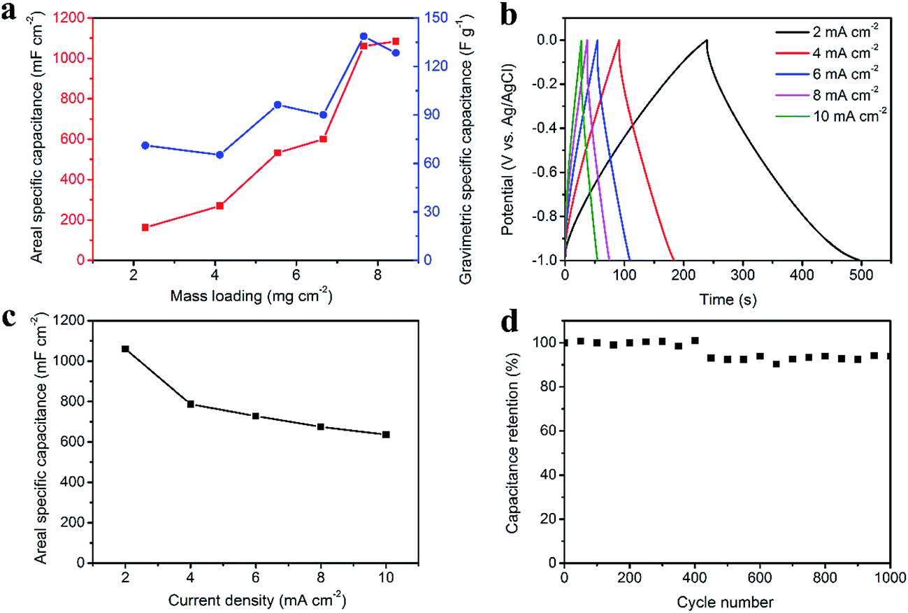 | ||
| Fig. 4 Electrochemical properties of CNT/rGO-coated fabric electrode. Dependence of areal and gravimetric specific capacitances on the mass loading of CNT/rGO, the current density is 2 mA cm−2 (a). Galvanostatic charge/discharge curves (b). Rate capability (c). Long-life performance (d). For the latter three tests, the CNT/rGO mass loadings of fabric electrodes are all 7.7 mg cm−2. | ||
Fig. 5 displays the electrochemical properties of PPy-coated fabric electrode. The potential window (vs. Ag/AgCl) is from 0 V to 0.8 V. Seen from Fig. 5a, the gravimetric specific capacitance increases with increasing the mass loading no more than 8.1 mg cm−2, at which the maximum gravimetric specific capacitance of 324.8 F g−1 is obtained. The areal specific capacitance increases with increasing the mass loading up to 9.9 mg cm−2, at which the maximum areal specific capacitance is 3090.6 mF cm−2. Here the current density is 2 mA cm−2. In order to match the CNT/rGO-coated fabric electrode with a mass loading of 7.7 mg cm−2, the mass loading of PPy-coated fabric is set as 5.7 mg cm−2. The matching detail is described as follows.
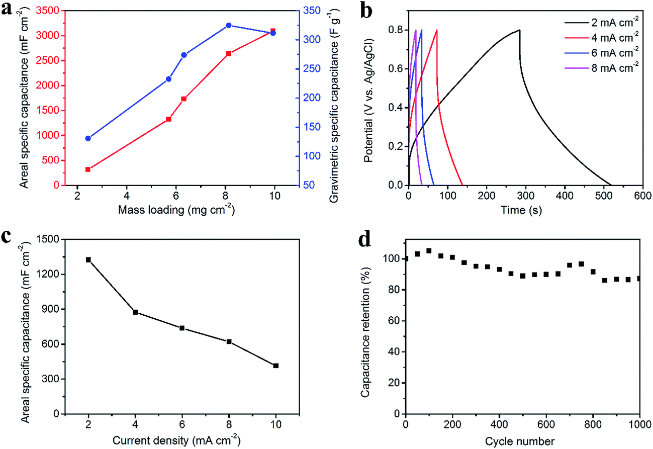 | ||
| Fig. 5 Electrochemical properties of PPy-coated fabric electrode. Dependence of areal and gravimetric specific capacitances on the mass loading of PPy, the current density is 2 mA cm−2 (a). Galvanostatic charge/discharge curves (b). Rate capability (c). Long-life performance (d). For the latter three tests, the PPy mass loadings of fabric electrodes are all 5.7 mg cm−2. | ||
In the asymmetric supercapacitor, PPy-coated and CNT/rGO-coated fabric electrodes work as the positive and negative electrodes, respectively. The charge balance between the positive and negative electrodes is shown in the equations:
| q+ = q− |
| q = CA × S × ΔU |
| CA+ × ΔU+ = CA− × ΔU− |
For the negative electrode, the mass loading of CNT/rGO was set as 7.7 mg cm−2 and then CA− is 1060 mF cm−2 and ΔU− is 1 V (Fig. 4a and b). Correspondingly, for the positive electrode, ΔU+ is 0.8 V and therefore CA+ should be 1325 mF cm−2. Consequently, the mass loading of PPy was chosen as 5.7 mg cm−2, because at which the PPy-coated fabric electrode can generate the similar areal specific capacitance of its counterpart (Fig. 5a).
A deep investigation of the electrochemical properties of the PPy-coated fabric electrode with a mass loading of 5.7 mg cm−2 was carried out. The GCD results are shown in Fig. 5b, which demonstrate the pseudo-capacitance type. The areal specific capacitances are 1325.4, 874.5, 737.2, 620.4 and 413.34 mF cm−2 at the current densities of 2, 4, 6, 8 and 10 mA cm−2, respectively (Fig. 5c). Fig. 5d represents the long-life performance, i.e., 87% capacitance retention after 1000 charge/discharge cycles. It can be learned that the PPy-coated fabric has a poorer cycle performance than the CNT/rGO-coated fabric. The reason is mainly the volume change of PPy under redox cycles, which is the common issue for the active materials of pseudo-capacitance type.17,42,43 Additionally, the cycle performance can be improved here to be 93% by coating an rGO layer on the PPy-coated fabric (Fig. S6†).
For the asymmetric supercapacitor, the PPy-coated fabric electrode was used as the positive electrode while the CNT/rGO-coated fabric electrode served as the negative electrode. The cyclic voltammetry (CV) curves of the asymmetric supercapacitor with different voltage windows at 10 mV s−1 exhibit in Fig. 6a. As expected, the voltage window of the asymmetric supercapacitor can be extended to 1.8 V. Fig. 6b illustrates the GCD curves at different current densities with a voltage window of 1.8 V, from which a small voltage drop was observed. The rate capability is shown in Fig. 6c, from which the maximum areal specific capacitance is 569.6 mF cm−2 at 1 mA cm−2. As for the long-life performance, the supercapacitor possesses 91% of its initial capacitance after cycling for 1000 cycles, demonstrating a good cycling stability (Fig. 6d).
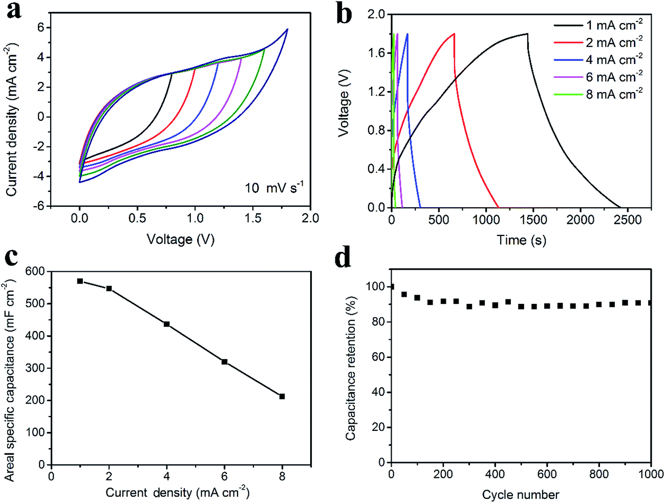 | ||
| Fig. 6 Electrochemical properties of the asymmetric supercapacitor. CV spectra at different working voltage windows (a). Galvanostatic charge/discharge curves at different current densities (b). Rate capability (c). Long-life performance (d). | ||
As for the energy density, considering the areal specific capacitance of 569.6 mF cm−2 at 1 mA cm−2 and the voltage window of 1.8 V, the areal energy density was calculated to be 0.26 mW h cm−2, which is the highest areal energy density among the available flexible supercapacitors (Fig. 7a, data extracted from Table S2†). Fig. 7b shows the CV curves under bending with angles of 0°, 90° and 180°. There is negligible change, verifying the excellent flexibility. Fig. 7c exhibits the stability of the asymmetric supercapacitor under bending for 100 times with a bending radius of 1 cm and an angle of 180°. Consequently, 87% of the initial capacitance is retained. Furthermore, two asymmetric supercapacitors in parallel can lighten as many as 14 LEDs at one time (Fig. 7d).
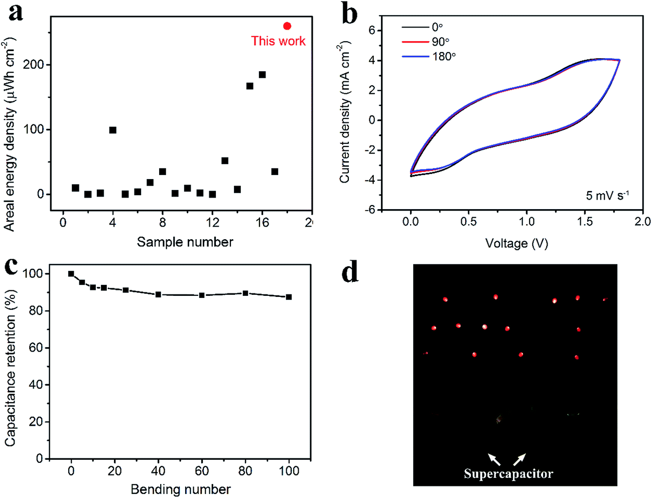 | ||
| Fig. 7 Performance of the asymmetric supercapacitor. Comparison on the areal energy density between this work and the reported flexible supercapacitors (data extracted from Table S2†) (a). CV spectra under bending with different bending angles (b). Capacitance retention under bending with different bending cycles. The bending angle is 180° (c). Lightening 14 LEDs at one time by using two asymmetric supercapacitors (each has an effective area of 1.5 cm2) (d). | ||
Conclusion
Here, an asymmetric supercapacitor was successfully assembled using CNT/rGO-coated fabric as the negative electrode and PPy-coated fabric as the positive electrode. Both electrodes achieve high areal specific capacitances. Therefore, the resulting asymmetric supercapacitor with a large voltage window of 1.8 V delivers a super-high areal energy density of 0.26 mW h cm−2. Furthermore, it presents an excellent stability under charge/discharge cycling and bending. The proposed strategy, i.e., loading high mass of active materials and still maintaining the porosity throughout the whole electrode thickness, is demonstrated to be effective for flexible supercapacitors and can be expanded to other electronic devices.Conflicts of interest
There are no conflicts to declare.Acknowledgements
This work was supported by the National Natural Science Foundation of China (51603038, 51673038), Program for Changjiang Scholars and Innovative Research Team in University (IRT16R13), Science and Technology Commission of Shanghai Municipality (16JC1400700), Innovation Program of Shanghai Municipal Education Commission (2017-01-07-00-03-E00055) and the Fundamental Research Funds for the Central Universities, DHU Distinguished Young Professor Program.References
- S. Zhai, H. E. Karahan, L. Wei, Q. Qian, A. T. Harris, A. I. Minett, S. Ramakrishna, A. K. Ng and Y. Chen, Energy Storage Materials, 2016, 3, 123–139 CrossRef.
- K. Jost, G. Dion and Y. Gogotsi, J. Mater. Chem. A, 2014, 2, 10776–10787 CAS.
- K. Wang, X. Zhang, C. Li, X. Sun, Q. Meng, Y. Ma and Z. Wei, Adv. Mater., 2015, 27, 7451–7457 CrossRef CAS PubMed.
- J. Yang, C. Fang, C. Bao, W. Yang, T. Yu, W. Zhu, F. Li, J. Liu and Z. Zou, RSC Adv., 2016, 6, 75186–75193 RSC.
- Z. S. Wu, K. Parvez, X. Feng and K. Mullen, Nat. Commun., 2013, 4, 2487 Search PubMed.
- J. W. Lee, A. S. Hall, J.-D. Kim and T. E. Mallouk, Chem. Mater., 2012, 24, 1158–1164 CrossRef CAS.
- J. Xue, Y. Zhao, H. Cheng, C. Hu, Y. Hu, Y. Meng, H. Shao, Z. Zhang and L. Qu, Phys. Chem. Chem. Phys., 2013, 15, 8042–8045 RSC.
- P. Simon, Y. Gogotsi and B. Dunn, Science, 2014, 343, 1210–1211 CrossRef CAS PubMed.
- Y. Gogotsi and P. Simon, Science, 2011, 334, 917–918 CrossRef CAS PubMed.
- Z. Fan, J. Yan, T. Wei, L. Zhi, G. Ning, T. Li and F. Wei, Adv. Funct. Mater., 2011, 21, 2366–2375 CrossRef CAS.
- S. Sarkar, S. Garain, D. Mandal and K. K. Chattopadhyay, RSC Adv., 2014, 4, 48220–48227 RSC.
- H. R. Ghenaatian, M. F. Mousavi and M. S. Rahmanifar, Electrochim. Acta, 2012, 78, 212–222 CrossRef CAS.
- C. Wu, X. Lu, L. Peng, K. Xu, X. Peng, J. Huang, G. Yu and Y. Xie, Nat. Commun., 2013, 4, 2431 Search PubMed.
- J. Zhi, C. Yang, T. Lin, H. Cui, Z. Wang, H. Zhang and F. Huang, Nanoscale, 2016, 8, 4054–4062 RSC.
- J. Yan, Q. Wang, T. Wei and Z. Fan, Adv. Energy Mater., 2014, 4, 1300816 CrossRef.
- Y. Shi, L. Pan, B. Liu, Y. Wang, Y. Cui, Z. Bao and G. Yu, J. Mater. Chem. A, 2014, 2, 6086–6091 CAS.
- X. Bai, X. Hu and S. Zhou, RSC Adv., 2015, 5, 43941–43948 RSC.
- T. G. Yun, B. Hwang, D. Kim, S. Hyun and S. M. Han, ACS Appl. Mater. Interfaces, 2015, 7, 9228–9234 CAS.
- M. Cakici, K. R. Reddy and F. Alonso-Marroquin, Chem. Eng. J., 2017, 309, 151–158 CrossRef CAS.
- X. Wu, L. Jiang, C. Long, T. Wei and Z. Fan, Adv. Funct. Mater., 2015, 25, 1648–1655 CrossRef CAS.
- W. Ma, S. Chen, S. Yang, W. Chen, W. Weng, Y. Cheng and M. Zhu, Carbon, 2017, 113, 151–158 CrossRef CAS.
- H. Y. Jin, Z. H. Peng, W. M. Tang and H. L. W. Chan, RSC Adv., 2014, 4, 33022–33028 RSC.
- F. M. Guo, R. Q. Xu, X. Cui, X. B. Zang, L. Zhang, Q. Chen, K. L. Wang and J. Q. Wei, RSC Adv., 2015, 5, 89188–89194 RSC.
- L. Ma, R. Liu, H. Niu, M. Zhao and Y. Huang, Compos. Sci. Technol., 2016, 137, 87–93 CrossRef CAS.
- D. Ghosh and C. K. Das, ACS Appl. Mater. Interfaces, 2015, 7, 1122–1131 CAS.
- C. Shi, Q. Zhao, H. Li, Z.-M. Liao and D. Yu, Nano Energy, 2014, 6, 82–91 CrossRef CAS.
- Z. Gao, N. Song, Y. Zhang and X. Li, RSC Adv., 2015, 5, 15438–15447 RSC.
- L. Li, Q. Zhong, N. D. Kim, G. Ruan, Y. Yang, C. Gao, H. Fei, Y. Li, Y. Ji and J. M. Tour, Carbon, 2016, 105, 260–267 CrossRef CAS.
- Y. Yang, Q. Huang, L. Niu, D. Wang, C. Yan, Y. She and Z. Zheng, Adv. Mater., 2017, 29, 1606679 CrossRef PubMed.
- H. Heydari and M. B. Gholivand, New J. Chem., 2017, 41, 237–244 RSC.
- L. Liu, W. Weng, J. Zhang, X. Cheng, N. Liu, J. Yang and X. Ding, J. Mater. Chem. A, 2016, 4, 12981–12986 CAS.
- W. S. Hummers and R. E. Offeman, J. Am. Chem. Soc., 1958, 80, 1339 CrossRef CAS.
- R. Kiefer, N. Aydemir, J. Torop, T. Tamm, R. Temmer, J. Travas-Sejdic, I. Must, F. Kaasik and A. Aabloo, Sens. Actuators, B, 2014, 201, 100–106 CrossRef CAS.
- W. Wang, W. Li, R. Zhang and J. Wang, Synth. Met., 2010, 160, 2255–2259 CrossRef CAS.
- C. Zhao, K. Shu, C. Wang, S. Gambhir and G. G. Wallace, Electrochim. Acta, 2015, 172, 12–19 CrossRef CAS.
- W. Liu, X. Yan, J. Lang, C. Peng and Q. Xue, J. Mater. Chem., 2012, 22, 17245–17253 RSC.
- I. A. Sahito, K. C. Sun, A. A. Arbab, M. B. Qadir and S. H. Jeong, Carbohydr. Polym., 2015, 130, 299–306 CrossRef CAS PubMed.
- G. Cai, Z. Xu, M. Yang, B. Tang and X. Wang, Appl. Surf. Sci., 2017, 393, 441–448 CrossRef CAS.
- J. Xu, D. Wang, Y. Yuan, W. Wei, L. Duan, L. Wang, H. Bao and W. Xu, Org. Electron., 2015, 24, 153–159 CrossRef CAS.
- J. Xu, D. Wang, Y. Yuan, W. Wei, S. Gu, R. Liu, X. Wang, L. Liu and W. Xu, Cellulose, 2015, 22, 1355–1363 CrossRef CAS.
- S. Peng, L. L. Fan, C. Z. Wei, X. H. Liu, H. W. Zhang, W. L. Xu and J. Xu, Carbohydr. Polym., 2017, 157, 344–352 CrossRef CAS PubMed.
- H. Lee, H. Kim, M. S. Cho, J. Choi and Y. Lee, Electrochim. Acta, 2011, 56, 7460–7466 CrossRef CAS.
- L. Zhu, L. Wu, Y. Sun, M. Li, J. Xu, Z. Bai, G. Liang, L. Liu, D. Fang and W. Xu, RSC Adv., 2014, 4, 6261–6266 RSC.
Footnote |
| † Electronic supplementary information (ESI) available. See DOI: 10.1039/c7ra08703a |
| This journal is © The Royal Society of Chemistry 2017 |