 Open Access Article
Oxygen electrode reactions of doped BiFeO3 materials for low and elevated temperature fuel cell applications
Rana Arslan Afzal†
a,
Ka-Young Park†a,
Sung-Hwa Choa,
Nam-In Kima,
Sung Ryul Choia,
Jung Hyun Kimb,
Hyung-Tae Limc and
Jun-Young Park *a
*a
aHMC, Department of Nanotechnology and Advanced Materials Engineering, Sejong University, Seoul 05006, Korea. E-mail: jyoung@sejong.ac.kr
bDepartment of Advanced Materials Science and Engineering, Hanbat National University, Daejeon, 34158, Korea
cSchool of Materials Science and Engineering, Changwon National University, Changwon 51140, Korea
First published on 11th October 2017
Abstract
Perovskite-based catalysts have been considered as candidate bifunctional electrocatalysts for oxygen evolution (OER) and reduction reactions (ORR) for unitized regenerative fuel cells (URFCs), because of their excellent catalytic activity and durability at low temperature. Furthermore, perovskite-structured materials can be utilized as an oxygen electrode material for solid oxide fuel cells (SOFCs) at even elevated temperatures due to their distinctive layered structure, providing great flexibility regarding the modification of their electronic configurations. Herein, we investigate whether alkaline earth metal-doped bismuth iron oxides (Bi0.6M0.4FeO3, M = Ba, Sr, Ca, and Mg) can act as both bifunctional catalysts for URFCs and cathode materials for SOFCs. Among these, Bi0.6Ca0.4FeO3 (BCFO) exhibits remarkable OER and ORR catalytic performances, with better long-term stability than that of a pristine BiFeO3 (BFO) catalyst in alkaline media at room temperature. Moreover, the DC conductivity of BCFO is more than 2 to 3 orders of magnitude higher than that of the BFO material at 500–700 °C for SOFCs. In addition, BCFO has a αTEC value of 12.4 × 10⁻⁶ K−1 at 25–650 °C, which is near those of yttria-stabilized zirconia and rare-earth-doped ceria electrolytes. Hence, BCFO demonstrates potential as an oxygen electrode material for operation at room and elevated temperatures.
1. Introduction
The global climate change with over-extraction of fossil fuels is bringing about the changeover from internal combustion engines to clean and sustainable renewable energy systems. In particular, electrochemical-based energy conversion and storage devices, such as fuel cells, water-splitting cells, and rechargeable metal–air batteries, are currently being investigated as sustainable energy systems with solar and wind systems.1–5 Among these, fuel cells are the most promising alternative, due to their low emission, high-efficiency, and reasonable energy density.6,7 The fuel cell is a clean electrochemical cell that converts the chemical energy from a hydrogen-containing fuel into electricity through electrochemical reactions with an oxidizing agent. Fuel cells are classified by the type of electrolyte and operating temperature they use.8,9 Polymer electrolyte membrane fuel cells (PEMFCs) use polymer membranes (e.g. Nafion) as an electrolyte at lower temperature (<100 °C). In contrast, solid oxide fuel cells (SOFCs) use ceramic electrolytes (e.g. yttria-stabilized zirconia) at high operating temperature (600–1000 °C). The electrolytic cell is an electrochemical cell that when external electrical energy is applied, produces hydrogen with oxygen.2,10–12 When electrical energy is applied to the electrodes, the ions (oxygen or proton) in the electrolyte are transported by redox reactions to an electrode with the opposite charge. Recently, integration of the two functionalities in a single electrochemical device, such as unitized regenerative fuel cells (URFCs, at <100 °C) and reversible solid oxide cells (RSOCs, at 600–1000 °C), has received great attention, due to the considerable simplification of system design, and the high power-to-weight ratio of energy conversion and storage systems.13–16Until now, designing highly active, cost-efficient, and durable air-electrode materials has been an essential part of these fuel cells (and electrolytic cells), especially for oxygen reduction (ORR) and evolution reactions (OER), to overcome the sluggish reaction kinetics and large overpotential associated with the transportation of four protons/electrons.17–20 For example, the current carbon-supported noble metal catalysts (e.g. Pt/C, PtRu/C, and Ir/C) are not feasible for large-scale commercialization of PEMFCs (or URFCs), due to high price and easy degradation of noble metal-based catalysts. Hence, one main goal of catalyst design for PEMFCs (and URFCs) is the development of highly active ORR and OER catalysts to replace and/or decrease the carbon-supported noble metal catalysts. Alternatively, non-precious metal compounds and metal-free catalysts, such as transitional metal (e.g. Co, Fe, and Ni) complexes, chalcogenides, transition metal oxides or nitrides, and macrocycles, have been found to have some catalytic activity for the oxygen electrode reaction.17,21–24 However, the complicated synthesis methods of catalysts are not suitable for reliable and scalable mass production. Further, relatively fast degradation of these catalysts was still observed during the accelerated stability test. Recently, several breakthroughs in activity and durability have been achieved in the field of non-precious metal catalysts. Suntivich et al.25,26 and Grimaud et al.27 demonstrated that the perovskite-based oxides with a general formula of ABO3, which show excellent oxygen ion diffusion rate and surface exchange coefficient, can be utilized as potential competitors to noble-based catalysts for the oxygen electrode of URFCs, due to their excellent oxygen ion diffusion rate and surface exchange coefficient. Furthermore, oxygen deficient perovskites and brownmillerites have even surpassed the activity of state-of-the-art IrO2 catalysts.28–30
Similarly, it is believed that the ORR is responsible for much of the performance loss of SOFCs with high cathodic overpolarization.31 In particular, SOFCs that operate in an intermediate temperature (IT) range (500–700 °C) are of great interest, due to their low degradation rates, materials cost, and easier sealing.32–36 However, with the decrease of operating temperature, the cathode overpotential increases significantly, because of the decreased values of the oxygen diffusion coefficient and oxygen surface exchange coefficient. Therefore, it is of great importance to develop high performance cathode materials for the IT–SOFCs. Currently, considerable efforts are devoted to cobalt-containing perovskite-type oxides, such as Ba0.5Sr0.5Co0.8Fe0.2O3−δ, La0.5Sr0.5CoO3−δ, and NdBa0.5Sr0.5Co0.8Fe0.2O5+δ, as some of the most promising cathodes for IT–SOFCs.32,37–39 These catalysts exhibited higher electrocatalytic activity toward ORR, with much higher electrical conductivity than conventional La0.5Sr0.5MnO3−δ cathodes. However, these cobalt-containing cathodes have some issues, like high cost, low phase stability, and high thermal expansion coefficients, leading to delamination of, or cracks in the cathode layer during the operation of SOFCs. Recently, many cobalt-free perovskite-type materials have been reported for the cathodes of IT–SOFCs. For example, the doped lanthanum ferrite perovskite oxides, La0.8Sr0.2FeO3−δ, Ba0.5Sr0.5Zn0.2Fe0.8O3−δ, and LaBaCuFeO5+δ, have been investigated as potential IT–SOFC cathodes.40–42
Herein we explore bismuth ferrite (BiFeO3, BFO) as a novel cobalt-free cathode IT–SOFC, considering that ferrite-based materials exhibit a reasonable electrochemical performance.43,44 The cathode material should possess high electrical conductivity for ORR with thermochemical compatibility for electrolyte at operating temperature.45 Furthermore, we examine the feasibility of BFO-based materials as the catalyst of ORR and OER for PEMFCs and URFCs, since BFO is one of the most attractive heterogeneous catalysts.46,47 The BFO-based materials are synthesized via a co-precipitation method, and their electrical conductivity and electrochemical performances are characterized in detail to investigate whether BFO performs well at both low (PEMFCs/URFCs) and elevated temperatures (SOFCs), expanding their practical applications. In addition, in order to improve the electrochemical performances of BFO as oxygen electrode materials, alkaline-earth metal ions (Mg2+, Ca2+, Sr2+, and Ba2+) are doped into the A-site of the Bi3+ ions. The doping of alkaline earth metal into BFO can result in the increment of transport rates of charge species for the electrochemical reactions through change of the electronic structure.
2. Experimental section
2.1 Preparations of BFO and doped-BFOs
The pristine- and modified-BFO catalysts were synthesized by a coprecipitation method. Stoichiometric amounts of bismuth(III) nitrate hydrate (Bi(NO3)3·xH2O, 99.999% purity, Alfa Aesar) and iron(III) nitrate nonahydrate (Fe(NO3)3·9H2O, 99.99% purity, Duksan) were dissolved in distilled water with glucose monohydrate (C6H12O6·H2O, Sigma-Aldrich) and sodium bicarbonate (NaHCO3, Sigma-Aldrich). During the precipitation, the solution was stirred continuously and heated at 60 °C for 18 h. Magnesium nitrate hexahydrate (Mg(NO3)2·6H2O, 98.0% purity, Sigma-Aldrich), calcium nitrate tetrahydrate (Ca(NO3)2·4H2O, 99.0% purity, Sigma-Aldrich), strontium(II) nitrate (Sr(NO3)2, 99% purity, Alfa Aesar), and barium(II) nitrate (Ba(NO3)2, 99.95% purity, Alfa Aesar) were added into BFO as an A-site dopant. The obtained materials were centrifuged, and washed several times with ethanol and distilled water to remove impurities and residues. Finally, the precipitates were dried in an electric oven at 80 °C for 12 h, and then calcined at 500 °C for 4 h.For the cathode materials in the SOFCs, the calcined powders were ground using a mortar and pestle, and pressed uniaxially (at 18 MPa) for 1 min. The pellets were then sintered at 700 °C for 4 h, with heating and cooling rates of 5 °C min−1.
2.2 Characterizations of BFO-based materials
The crystalline phase of all samples was examined by X-ray diffraction (XRD, D/MAX 2500, Rigaku) with Cu-Kα radiation in the range of 20–80° with 0.02° step size. Rietveld refinements were performed by Fullprof software to reveal the lattice parameters and crystal structure. The morphology and microstructure of the synthesized catalysts were observed by field emission-scanning electron microscopy (FE-SEM, S-4700, Hitachi High Tech) with energy dispersive X-ray spectroscopy (EDX, Oxford Instruments) to analyze the material composition. The specific surface area of catalysts was analyzed by performing nitrogen sorption measurement at 77 K on a 3Flex surface characterization analyzer (Micromeritics, USA). The surface area was estimated using the Brunauer–Emmett–Teller (BET) equation, using 3Flex software. Pore size distributions were calculated using the Barrett–Joyner–Halenda (BJH) method from the adsorption branch of the isotherm. The X-ray photoelectron spectroscopy (XPS) was performed by spectrometer (theta probe angle-resolved XPS system, Thermo Fisher Scientific) with a monochromatized Al Kα (1486.6 eV) as X-ray source. The chamber was kept as a vacuum condition, 1 × 10⁻¹⁰ Torr, and the measured data were calibrated using C 1s peak (284.6 eV) as reference. The thermal expansion coefficient (TEC) of the sintered BFO-based sample was measured using a dilatometer (Tesatronic TT-80) between room temperature and 650 °C with a heating/cooling rate of 5 °C min−1 in air atmosphere. The average TECs were found from the linear section of dilatometric data.2.3 Electrochemical analysis of BFO-based catalysts
Catalyst suspensions were prepared from 10 mg of BFO-based catalyst, 5 mg carbon black (Vulcan XC-72R, Cabot), 5 wt% Nafion solution (Sigma-Aldrich), isopropanol (Daejung), and de-ionized (DI) water; they were then ultrasonicated for 30 min to make the homogeneous solution. The slurry was pipetted onto the glassy carbon by a microsyringe (Daihan Sci.), then heated at 60 °C to dry. 0.1 M potassium hydroxide (KOH) solution was used as electrolyte. Electrochemical measurements were carried out by rotating disk electrode (RDE) system (RRDE-3A, ALS) with galvanostat/potentiostat electrochemical analyzer (SP-150, BioLogic). In the three-electrode system, Hg/HgO (sat. NaOH), Pt wire, and catalyst coated-glassy carbon were applied as reference, counter, and working electrode, respectively. The measured potentials were converted to the reversible hydrogen electrode (RHE) scale according to the following relation;| V (vs. RHE) = V (vs. Hg/HgO) + 0.098 + 0.059pH | (1) |
The measured potentials were also compensated as 85% by iR-correction method. Pre-conditioning of the materials was conducted by cyclic voltammetry (CV) technique to clean the surface of the materials in N2-saturated 0.1 M KOH solution between 0.05 and 1.2 V for 50 cycles at a scan rate of 100 mV s−1. Linear sweep voltammetry (LSV) was performed to evaluate the OER and ORR performances, using the RDE from 1.2 to 1.7 V (OER) and 1.1 to 0.2 V (ORR) at a scan rate of 5 mV s−1 and a rotation of 1600 rpm in 0.1 M KOH solution. 20 wt% of Ir/C (Premetek) and Pt/C (Johnson Matthey) were used as reference catalysts for OER and ORR, respectively. The accelerated durability tests (ADTs) were carried out for OER (1.2–1.7 V) and ORR (0.6–1.2 V) potential ranges, respectively, at a scan rate of 200 mV s−1 for 1500 cycles in electrolyte solution with rotation.
For four-probe DC conductivity measurements, the sintered BFO and BCFO pellets were ground into rectangular-type bars. Four platinum wires were bound to each sample to form four contacts and leads for DC four-probe measurements. The electrical conductivity of the samples was measured by using a potentiostat/galvanostat instrument (SP-240, Biologic). By passing current and recording the voltage of the samples, four-probe DC conductivity was performed as a function of temperature in ambient air atmosphere.
3. Results and discussion
3.1 Characterizations of the doped-BFOs
Fig. 1 shows the XRD patterns of calcined pristine and alkaline earth metal oxide (MgO, CaO, SrO, and BaO)-doped BiFeO3 (BFO) powders at 500 °C. In all cases, the major phases are consistent with a rhombohedral phase corresponding to the crystalline structure of trigonal BFO (JCPDS #72-2035).48,49 Peaks that relate to the impurity (Bi2Fe4O9) are observed at 28° and 30°, as marked with the symbol in Fig. 1(a), apart from the perovskite phase. However, the main diffraction peaks of (010), (110), (111), (020), (120), and (121) are sharp, indicating that alkaline earth metal dopants did not destroy the original lattice structure of BFO. Furthermore, it could be reasonably assumed that such a small amount of doping did not appear to influence the electrochemical performance. The average crystallite sizes of the materials were calculated by Scherrer equation (Table 1). BFO showed a larger crystallite size of 4.99 nm, compared to that of the doped BFO materials. Bi0.6Ba0.4FeO3 (BBFO), Bi0.6Sr0.4FeO3 (BSFO), Bi0.6Ca0.4FeO3 (BCFO), and Bi0.6Mg0.4FeO3 (BMFO) exhibited 3.63, 3.56, 3.78, and 3.66 nm of crystallite size, respectively, indicating that doping of alkaline earth metal contributed to decrease of the crystallite size of the BFO.21,50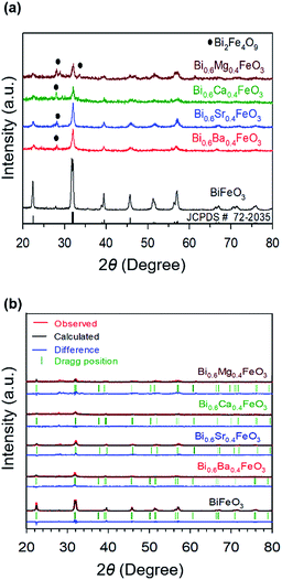 | ||
| Fig. 1 (a) XRD patterns of calcined pristine and alkaline earth metal oxide (MgO, CaO, SrO, and BaO)-doped BiFeO3 (BFO) powders at 500 °C, with (b) their Rietveld refinement results. | ||
| Catalyst | a-axis (Å) | b-axis (Å) | c-axis (Å) | Chi2 (χ2) | Crystallite size (nm) |
|---|---|---|---|---|---|
| BiFeO3 | 5.580 | 5.580 | 13.862 | 0.71 | 4.99 |
| Bi0.6Ba0.4FeO3 | 5.591 | 5.591 | 13.771 | 2.60 | 3.63 |
| Bi0.6Sr0.4FeO3 | 5.608 | 5.608 | 13.830 | 1.93 | 3.56 |
| Bi0.6Ca0.4FeO3 | 5.578 | 5.578 | 13.727 | 1.46 | 3.78 |
| Bi0.6Mg0.4FeO3 | 5.585 | 5.585 | 13.849 | 3.76 | 3.66 |
To better understand the nature of the detailed structural information of BFO-based materials, the XRD patterns of overall catalysts were further analyzed by the Rietveld refinement using the Fullprof program,51 and Fig. 1(b) shows the refinement results. The diffraction peaks of all samples were indexed as a rhombohedral perovskite structure with space group of R3cH, in agreement with the previous results.49,52 Fig. 2 shows that the unit cell can be described in a hexagonal frame of reference, with the hexagonal c-axis parallel to the diagonals of the perovskite cube ([111]pseudocubic ‖ [001]hexagonal). The average hexagonal lattice parameters are ahex = 5.59 Å and chex = 13.80 Å, and Table 1 shows the refinement parameters of BFO materials.
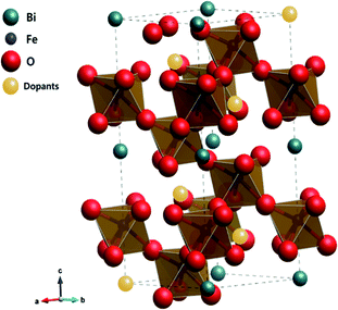 | ||
| Fig. 2 Crystalline structure of alkaline earth metal oxide-doped BFO simulated by the Rietveld refinement. | ||
The chi-square (χ2) values of BFO-based materials are reasonably low (χBFO2 = 0.703, χBBFO2 = 2.60, χBSFO2 = 1.93, χBCFO2 = 1.46, and χBMFO2 = 3.76), as the criteria for judging the quality of the profile fit. It is clear that the alkaline earth metals are doped into the A-site of the Bi3+ to maintain the structural stability in the ABO3 structure (considering the tolerance factor of perovskite,  ), since there is a large difference in ionic radii between A and B cations. Furthermore, the valence of B cations should be varied by oxygen vacancies to maintain the electroneutrality of the unit cell, because the B cations is surrounded by octahedron of oxygen anions.53,54 In contrast, the alkaline earth metals are non-magnetic materials with a fixed ionic valence as M2+ (e.g. Mg2+, Ca2+, Sr2+, and Ba2+). The morphology and microstructure of the BFO catalysts were examined by FE-SEM. Fig. 3 shows that the BFO-containing catalysts displayed a cotton ball-like structure with agglomerated features, typical of the morphology of coprecipitated ceramic powders after calcination. The doping strategy effectively reduced the average particle size of the BFO from 84 to 40 nm, due to the interaction between dopants and surfaces (or grain boundaries), which reduces the interfacial energy at those regions.55 This trend was in agreement with the BET results of catalysts. The BET surface area of catalysts was analyzed by nitrogen adsorption–desorption isotherms as shown in Fig. 4(a), and was determined to be 2.8, 4.8, 7.4, 9.4, and 15.1 m2 g−1 for the BFO, BBFO, BSFO, BCFO, and BMFO, respectively. That is, the doping of alkaline earth metal into BFO effectively increased the surface area of the catalysts. Fig. 4(b) shows the total pore volume and pore size, which were obtained from the adsorption branches by using the BJH method. The formed pore volume and diameter of the pristine BFO were also increased by the addition of alkaline earth metal, and the mean pore diameter was 17.4, 25.7, 30.7, 22.5, and 34.6 nm for the BFO, BBFO, BSFO, BCFO, and BMFO, respectively. Table 2 lists all of the detailed data for the BET surface area, pore size, and pore volume of the BFO-based catalysts.
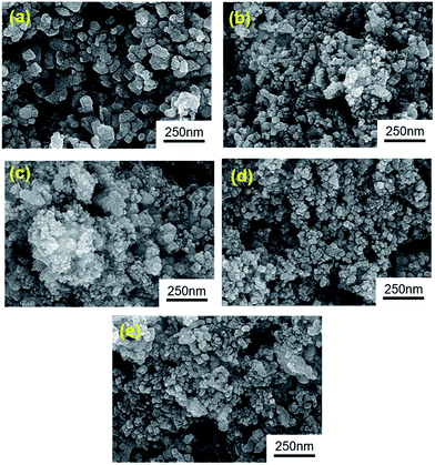 | ||
| Fig. 3 Morphology and microstructure of the BFO-based catalysts examined by FE-SEM; (a) BiFeO3, (b) Bi0.6Ba0.4FeO3, (c) Bi0.6Sr0.4FeO3, (d), Bi0.6Ca0.4FeO3, and (e) Bi0.6Mg0.4FeO3. | ||
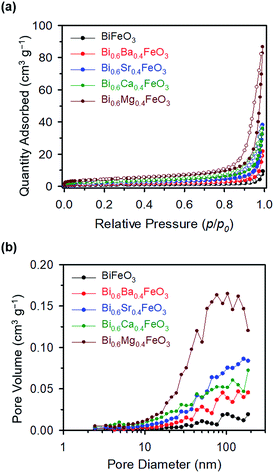 | ||
| Fig. 4 (a) Nitrogen adsorption–desorption isotherms, and (b) total pore volume and pore size, obtained from adsorption branches of the BFO-based catalysts. | ||
| Catalyst | BET (m2 g−1) | Total pore volume [p/p0 = 0.990] (cm3 g−1) | Mean pore diameter (nm) |
|---|---|---|---|
| BiFeO3 | 2.8 | 0.012 | 17.4 |
| Bi0.6Ba0.4FeO3 | 4.8 | 0.031 | 25.7 |
| Bi0.6Sr0.4FeO3 | 7.4 | 0.056 | 30.7 |
| Bi0.6Ca0.4FeO3 | 9.4 | 0.053 | 22.5 |
| Bi0.6Mg0.4FeO3 | 15.1 | 0.130 | 34.6 |
3.2 Electrocatalytic activity and stability of the BFO-based catalysts for OER and ORR at room temperature
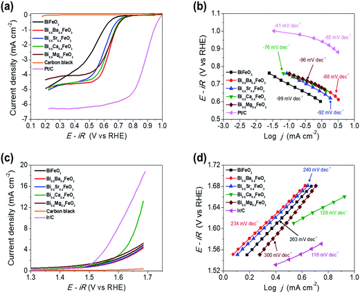
The electrocatalytic activity of the BFO-based catalysts was investigated with the Hg/HgO reference electrode using RRDE measurements in an O2-saturated 0.1 M KOH solution at a rotation speed of 1600 rpm. BFO-based particles were mixed with carbon black for the ORR activity measurements, to overcome the electronic conductivity limitations. Fig. 5(a) shows the ORR polarization curves of the catalysts.The electrochemical performances of carbon black, Pt/C (20 wt% Pt, Johnson Matthey), and Ir/C (20 wt%, Premetek) were measured and plotted for comparison purpose. It is clearly observed that doping of alkaline earth metal into BFO makes a remarkable improvement to the ORR activity. In particular, Ca-doped BFO (BCFO) shows the best catalytic behavior for ORR among these catalysts. The onset (ηonset) and half-wave potential (ηhalf-wave at −3 mA cm−2) of BCFO are 0.705 and 0.619 V, respectively, as the crucial parameter to determine the level of intrinsic ORR activity, while those of BFO are 0.633 and 0.480 V. The kinetics of the BFO-based catalysts were investigated from their Tafel plots using the Tafel equation (η = a + b![[thin space (1/6-em)]](https://www.rsc.org/images/entities/char_2009.gif) log
log![[thin space (1/6-em)]](https://www.rsc.org/images/entities/char_2009.gif) j, where η and j are the overpotential and current density, respectively) in Fig. 5(b). The measured Tafel slopes of BFO, BBFO, BSFO, BCFO, and BMFO catalysts are −99, −88, −92, −76, and −96 mV dec−1, respectively. Moreover, the doped BFO materials show an increment in the exchange current density (j0) from 3.23 × 10⁻⁹ (pristine BFO) to 5.17 × 10⁻⁸ mA cm−2 (BCFO). Table 3 shows the values of the ORR polarization curves.
j, where η and j are the overpotential and current density, respectively) in Fig. 5(b). The measured Tafel slopes of BFO, BBFO, BSFO, BCFO, and BMFO catalysts are −99, −88, −92, −76, and −96 mV dec−1, respectively. Moreover, the doped BFO materials show an increment in the exchange current density (j0) from 3.23 × 10⁻⁹ (pristine BFO) to 5.17 × 10⁻⁸ mA cm−2 (BCFO). Table 3 shows the values of the ORR polarization curves.
| Catalysts | ORR | OER | ||||||
|---|---|---|---|---|---|---|---|---|
| ORR onset potential, ηonset | EORR/V (at j = −3 mA cm−2) | Tafel slope/mV dec−1 | Exchange current density/mA cm−2 | OER onset potential, ηonset | jOER/mA cm−2 (at 1.65 V) | Tafel slope/mV dec−1 | Exchange current density/mA cm−2 | |
| BiFeO3 | 0.633 | 0.480 | −99 | 3.23 × 10⁻⁹ | 1.606 | 3.63 | 263 | 9.24 × 10⁻² |
| Bi0.6Ba0.4FeO3 | 0.685 | 0.578 | −88 | 1.77 × 10⁻⁹ | 1.619 | 3.06 | 234 | 5.02 × 10⁻² |
| Bi0.6Sr0.4FeO3 | 0.702 | 0.605 | −92 | 2.81 × 10⁻⁹ | 1.618 | 3.29 | 240 | 5.88 × 10⁻² |
| Bi0.6Ca0.4FeO3 | 0.705 | 0.619 | −76 | 5.17 × 10⁻⁸ | 1.609 | 6.93 | 128 | 3.24 × 10⁻¹ |
| Bi0.6Mg0.4FeO3 | 0.708 | 0.593 | −96 | 1.33 × 10⁻⁹ | 1.619 | 4.04 | 300 | 1.63 × 10⁻¹ |
The oxygen evolution activities of pristine and doped BFOs were also measured in a 0.1 M KOH solution at room temperature by rotating disk electrode (RDE) system. Fig. 5(c) demonstrates the linear sweep voltammetry (LSV) curves from 1.3 to 1.7 V vs. RHE at a scan rate of 5 mV s−1 to minimize the capacitive current. It is evident that the BCFO is the most highly active for the OER, compared to those of BFO, BBFO, BSFO, and BMFO catalysts. The current density for OER (jOER) of BCFO shows a significantly high value of 6.93 mA cm−2, at a fixed overpotential of 0.42 V (1.65 V vs. RHE), which is approximately 2 times higher than that of the other catalysts. Fig. 5(d) also shows corresponding Tafel plots for OER, and the catalysts showed Tafel slopes ranging from 128 to 300 mV dec−1. The BCFO catalyst exhibits the lowest Tafel slope of 128 mV dec−1 with high j0 (3.24 × 10⁻¹ mA cm−2), while BFO shows 263 mV dec−1 and 9.24 × 10⁻² mA cm−2 for OER. Detailed electrochemical parameters of the BFO catalysts were tabulated in Table 3.
In order to grasp the pathway for ORR, the Koutecky–Levich (K–L) plots of the BFOs materials are obtained from ORR polarization curves. The kinetic parameters can be determined by the following Koutecky–Levich equations;56–59
| 1/j = 1/jL + 1/jK = 1/(Bω1/2) + 1/jK | (2) |
| B = 0.62nFC0(D0)3/2ν−1/6 | (3) |
| jK = nFkC0 | (4) |
![[thin space (1/6-em)]](https://www.rsc.org/images/entities/char_2009.gif) 485C mol−1), C0 and D0 are the saturation concentration (1.26 × 10⁻⁶ mol cm−3) and diffusion coefficient (1.93 × 10⁻⁵ cm2 s−1) of oxygen gas, respectively, ν is the kinematic viscosity of the electrolyte (0.1 M KOH, 1.09 × 10⁻² cm2 s−1), and k is the electron transfer rate constant, respectively. The K–L plots shows a linear shape in Fig. 6 and the number of electrons (n) are calculated from their slopes as 2.6 (BFO), 3.4 (BMFO), 3.5 (BBFO and BSFO), 3.7 (BCFO) at 0.5 V, respectively, indicating that the dopants (Ba, Sr, Ca, and Mg) contribute to significantly improve the intrinsic ORR activity of BFO. This result may be due to the enhanced oxygen catalytic activity through modification of the electrical properties of catalysts by doping of alkaline earth metal oxides.
485C mol−1), C0 and D0 are the saturation concentration (1.26 × 10⁻⁶ mol cm−3) and diffusion coefficient (1.93 × 10⁻⁵ cm2 s−1) of oxygen gas, respectively, ν is the kinematic viscosity of the electrolyte (0.1 M KOH, 1.09 × 10⁻² cm2 s−1), and k is the electron transfer rate constant, respectively. The K–L plots shows a linear shape in Fig. 6 and the number of electrons (n) are calculated from their slopes as 2.6 (BFO), 3.4 (BMFO), 3.5 (BBFO and BSFO), 3.7 (BCFO) at 0.5 V, respectively, indicating that the dopants (Ba, Sr, Ca, and Mg) contribute to significantly improve the intrinsic ORR activity of BFO. This result may be due to the enhanced oxygen catalytic activity through modification of the electrical properties of catalysts by doping of alkaline earth metal oxides.
 | ||
| Fig. 6 Koutecky–Levich plots of alkaline earth metal-doped BFOs with the number of electrons at various ORR potentials; (a) 0.45 V, (b) 0.5 V, and (c) 0.55 V. | ||
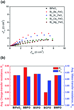
In order to ascertain the chemical state (electronic state) for the individual elements, the XPS spectra are carried out (Fig. 7). It is observed that the spectra of Bi 4f and Fe 2p are almost similar for all BFO-based materials. The peaks in O 1s spectra at 530.4 and 529.15 eV are associated with the Bi2–(O 1s)3 and Fe2–(O 1s)3 bonds, respectively.60,61 The Bi2–(O 1s)3 peaks were shifted in BBFO and BSFO to higher binding energy, while to lower binding energy in BMFO. This indicates that the binding energy between Bi and lattice oxygen can be varied by the dopant ions (that is, higher binding energy for larger ions and lower for smaller ions). Ca-doped BFO shows negligible change in the O 1s spectra due to the similar ionic size of Bi3+ and Ca2+ (Bi3+ = 1.17 Å, Ca2+ = 1.14 Å), which is consistent with the results of previous studies.62–64 That is, small difference of ionic radii between Bi3+ and Ca2+ decreases the crystallite size with structural stability including the improved ORR and OER activities.65–67 The excellent performance of BCFO for OER and ORR is also due to the rapid charge-transport property of the BCFO catalyst. The doping of CaO into BFO can result in the increment of transport rates of charge species for the electrochemical reactions through the change of electronic structure. In order to confirm this explanation, electrochemical impedance spectroscopy (EIS) was performed in a 0.1 M KOH electrolyte at room temperature. Fig. 8(a) shows the complex-plane Nyquist plots of the BFO-based catalyst at a potential of 1.65 V vs. RHE. The charge transfer (Rct, as determined from the diameter of the semicircle of the Nyquist plot at a high frequency region) and mass transfer resistances (Rmt, at a low frequency region) were obtained from the fitted equivalent circuit using EC-Lab software, and are shown in Fig. 8(b). It is clear that the doping of CaO resulted in significant decrease of the Rct of the BFO. Rct of the BCFO decreased from 0.73 (BFO) to 0.61 ohm cm2 (BCFO), while the Rmt showed negligible change. This finding is concordant with the results of the oxygen activities (OER and ORR) of the BFO-based catalysts presented in Fig. 5. Ineffective change of Rct of the BBFO, BSFO, and BMFO with oxygen activity needs to more understanding as future works.
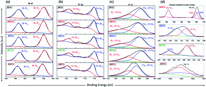 | ||
| Fig. 7 XPS spectra of BFO-based catalysts. (a) Bi 4f, (b) Fe 2p, (c) O 1s, and (d) dopants (Ba 3d, Sr 3d, Ca 2p, and Mg 1s). | ||
Fig. 9 shows the effect of CaO content of the BFO on the oxygen activity. The performances of Ca-doped BFO displayed with Pt/C and Ir/C for ORR and OER, respectively. In Fig. 9(a), the ORR activity of BCFO catalysts was investigated in a 0.1 M KOH solution at a rotation speed of 1600 rpm (RRDE). With increasing CaO content at room temperature, the ORR activity (in ηhalf-wave at −3 mA cm−2) increased until 40 mol%. Further increases in the CaO content resulted in decreased ORR activity of the BCFO catalysts. The ηhalf-wave of BCFO was 0.610, 0.611, 0.616, 0.619, and 0.616 V for 10, 20, 30, 40, and 50 mol% CaO doping, respectively. For the OER activity, 40 mol% CaO doped BFO showed the lowest overpotential at a fixed current density of 5 mA cm−2, as shown in the LSV curves of Fig. 9(b). The jOER of BCFO was 5.09, 5.58, 5.19, 6.92, and 4.22 mA cm−2, at a fixed overpotential of 0.42 V (1.65 V vs. RHE).
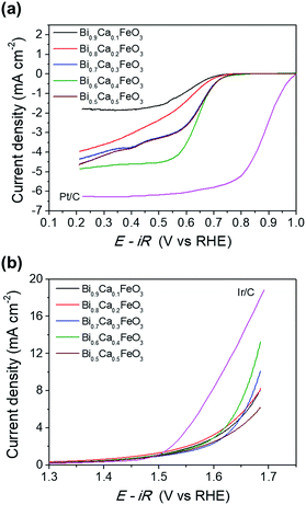 | ||
| Fig. 9 (a) ORR polarization curves and (b) OER polarization curves of the Bi1−xCaxFeO3 (x = 0.1, 0.2, 0.3, 0.4, and 0.5). | ||
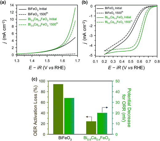
For sustainable use for bifunctional OER and ORR catalysts, long-term stability is one of the important factor.21,47,68 The durability of BFO and BCFO was examined by the potential cycling method from 1.25 to 1.65 V (for OER) and 0.6 to 1.0 V (for ORR) for 1500 cycles in 0.1 M KOH solution. Fig. 10(a) shows the polarization curves of the OER stability tests for BFO and BCFO. After potential cycling, the OER activities of BCFO decreased from 6.98 to 5.22 mA cm−2 at 1.65 V, resulting in a 24% loss of activity; whereas, BFO underwent a more severe degradation of 95.1% (from 3.57 to 0.172 mA cm−2) (Fig. 10(a) and (c)). Fig. 10(b) and (c) show the ORR polarization curves of BFO and BCFO before and after potential cycling, and in comparison with that of the BFO catalyst. The potential decrease for ORR clearly reveals that the durability of BCFO is greater than that of the BFO. The potential of the BCFO decreased 20 mV at ηhalf-wave, whereas that of BFO decreased substantially by 34 mV after 1500 cycles. The better durability of BCFO for bifunctional oxygen reactions was mainly due to the robust crystal structure of BCFO by doped Ca2+ ions, which could inhibit the agglomeration and amorphization of particles during the water oxidation and reduction reactions. Many researchers reported that the surface oxidation and amorphization of oxide and agglomeration of nanoparticles are responsible as the main degradation mechanisms of OER and ORR activities during the long-term electrochemical reactions associated with oxygen.21,51,69–71
3.3 Thermomechanical and electrical properties of BFO and BCFO at high temperature
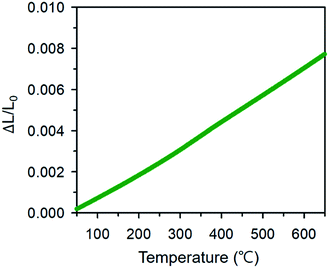
A major technical challenge in SOFC research is to develop cathode materials of similar thermal expansion coefficient (TEC) to those of other cell components (anode, electrolyte, and contact functional layers) to mitigate thermomechanical stresses, especially during thermal cycling.7,39,72–75 The TEC (αTEC) commonly describes how a compound changes unit cell parameter in response to temperature, and is defined as;
 | (5) |
Therefore, it would be beneficial to use BCFO as a cathode material with conventional electrolytes for IT–SOFCs, because cracking and delamination of the cell can be greatly reduced at high operating temperatures, through the relieving of thermal stress at the interface.
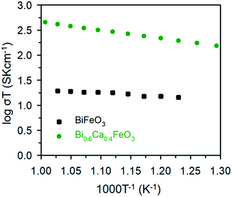
The electrical properties of the BFO and BCFO compounds were studied by four-probe DC technique between 500 and 700 °C. Fig. 12 compares the total conductivity of the BFO and BCFO cathodes in air conditions. The DC conductivity data of the BCFO were more than 2–3 orders of magnitude higher than that of the BFO material in all the measured temperature range (particularly at intermediate temperature). This indicates that the doping of CaO contributes to significantly increase of the conductivity of BFO, in agreement with the results of ORR and OER at room temperature. In addition, the conductivity of BCFO increased with increase of operation temperature, indicating the semiconducting behavior of BCFO. In order to examine the long-term stability of materials, the electrical conductivity of BCFO was also measured as a function of time under air at 550 °C, as shown in Fig. 13. After long-term operation for 115 h, the change in the conductivity of BCFO was negligible, indicating the robustness and stability of the BCFO. That is, the BCFO showed promise for SOFCs as a cathode material.
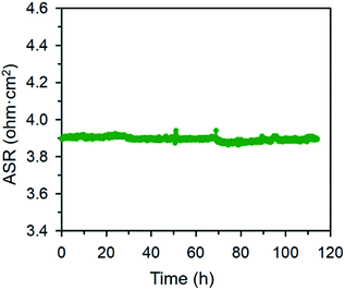 | ||
| Fig. 13 Area specific resistances of the BCFO as a function of time at 650 °C for the stability test. | ||
4. Conclusions
We explored, for the first time, the use of bismuth ferrite (BFO)-based materials as a novel cobalt-free oxygen electrode catalyst at both low and high temperatures. Among these, CaO-doped BFO (BCFO) showed good catalytic activity and high stability for OER and ORR in URFCs and SOFCs. The onset and half-wave potentials at −3 mA cm−2 of BCFO were 0.705 and 0.619 V, respectively for ORR, while those of BFO were 0.633 and 0.480 V. The measured Tafel slopes of BFO and BCFO catalysts were −99 and −76 mV dec−1, respectively, for ORR. The current density for OER of BCFO showed a significantly high value of 6.93 mA cm−2, at a fixed overpotential of 0.42 V (1.65 V vs. RHE), which was approximately 2 times higher than that of other BFO-based catalysts. The excellent performance of BCFO for OER and ORR was because the doping of CaO into BFO resulted in the increment of the transport rates of charge species for the electrochemical reactions through the change of electronic structure, which was confirmed by EIS measurements. BCFO also recorded outstandingly lesser performance decay ratios after the cycling tests for OER and ORR than that of the pristine BFO in an alkaline medium. For further improvement of the activity and stability, BFO-based electrocatalyst would be hybridized with the nitrogen doped reduced graphene oxide, heteroatom doped carbon nanotubes (or carbon nanofiber), and conducting polymeric materials (such as polyaniline) as future works. We also investigated the electrical conductivity of BCFO at elevated temperatures, and BCFO exhibited 2–3 orders higher values at 500−700 °C than did BFO. In summary, the feasibility of BCFO was demonstrated as the oxygen electrode material for ORR and OER at both room temperature and elevated temperatures.Conflicts of interest
There are no conflicts to declare.Acknowledgements
This research was supported by the Mid-career Researcher and Technology Development Program to Solve Climate Changes through the National Research Foundation of Korea (NRF-2014R1A2A1A11052276 and NRF-2015M1A2A2057042) and by the Industrial Technology Innovation and International Collaborative Energy Technology R&D Program of the Korea Institute of Energy Technology Evaluation and Planning (KETEP) granted financial resource from the Ministry of Trade, Industry & Energy, Republic of Korea (No. 20153010031940 and No. 20158520030830).References
- A. S. Aricò, P. Bruce, B. Scrosati, J.-M. Tarascon and W. van Schalkwijk, Nat. Mater., 2005, 4, 366 CrossRef PubMed.
- S. Park, Y. Shao, J. Liu and Y. Wang, Energy Environ. Sci., 2012, 5, 9331 CAS.
- J. C. Burns, A. Kassam, N. N. Sinha, L. E. Downie, L. Solnickova, B. M. Way and J. R. Dahn, J. Electrochem. Soc., 2013, 160, A1451 CrossRef CAS.
- G. Wang, L. Zhang and J. Zhang, Chem. Soc. Rev., 2012, 41, 797 RSC.
- O. Gröger, H. A. Gasteiger and J.-P. Suchsland, J. Electrochem. Soc., 2015, 162, A2605 CrossRef.
- E. D. Wachsman and K. T. Lee, Science, 2011, 334, 935 CrossRef CAS PubMed.
- B. C. H. Steele and A. Heinzel, Nature, 2001, 414, 345 CrossRef CAS PubMed.
- V. Ramani, Electrochem. Soc. Interface, 2006, 15, 41 CAS.
- L. Carrette, K. A. Friedrich and U. Stimming, ChemPhysChem, 2000, 1, 162 CrossRef CAS PubMed.
- A. Brisse, J. Schefold and M. Zahid, Int. J. Hydrogen Energy, 2008, 33, 5375 CrossRef CAS.
- F. Mitlitsky, B. Myers and A. H. Weisberg, Energy Fuels, 1998, 12, 56 CrossRef CAS.
- S.-D. Yim, W. Y. Lee, Y.-G. Yoon, Y.-J. Sohn, G.-G. Park, T.-H. Yang and C.-S. Kim, Electrochim. Acta, 2004, 50, 713 CrossRef CAS.
- G. Chen, S. R. Bare and T. E. Mallouk, J. Electrochem. Soc., 2002, 149, A1092 CrossRef CAS.
- J. Pettersson, B. Ramsey and D. Harrison, J. Power Sources, 2006, 157, 28 CrossRef CAS.
- M. A. Laguna-Bercero, J. Power Sources, 2012, 203, 4 CrossRef CAS.
- M.-B. Choi, B. Singh, E. D. Wachsman and S.-J. Song, J. Power Sources, 2013, 239, 361 CrossRef CAS.
- Y. Gorlin and T. F. Jaramillo, J. Am. Chem. Soc., 2010, 132, 13612 CrossRef CAS PubMed.
- B. Hua, Y.-Q. Zhang, N. Yan, M. Li, Y.-F. Sun, J. Chen, J. Li and J.-L. Luo, Adv. Funct. Mater., 2016, 26, 4106 CrossRef CAS.
- W. T. Hong, M. Risch, K. A. Stoerzinger, A. Grimaud, J. Suntivich and Y. Shao-Horn, Energy Environ. Sci., 2015, 8, 1404 CAS.
- D. N. Leonard, A. Kumar, S. Jesse, M. D. Biegalski, H. M. Christen, E. Mutoro, E. J. Crumlin, Y. Shao-Horn, S. V. Kalinin and A. Y. Borisevich, Adv. Energy Mater., 2013, 3, 788 CrossRef CAS.
- N.-I. Kim, Y. J. Sa, S.-H. Cho, I. So, K. Kwon, S. H. Joo and J.-Y. Park, J. Electrochem. Soc., 2016, 163, F3020 CrossRef CAS.
- M. Jiang, Y. Li, X. Sun and X. Duan, Inorg. Chem. Front., 2016, 3, 630 RSC.
- T. Y. Ma, J. Ran, S. Dai, M. Jaroniec and S. Z. Qiao, Angew. Chem., Int. Ed., 2015, 54, 4646 CrossRef CAS PubMed.
- R. Cao, J.-S. Lee, M. Liu and J. Cho, Adv. Energy Mater., 2012, 2, 816 CrossRef CAS.
- J. Suntivich, H. A. Gasteiger, N. Yabuuchi, H. Nakanishi, J. B. Goodenough and Y. Shao-Horn, Nat. Chem., 2011, 3, 546 CrossRef CAS PubMed.
- J. Suntivich, K. J. May, H. A. Gasteiger, J. B. Goodenough and Y. Shao-Horn, Science, 2011, 334, 1383 CrossRef CAS PubMed.
- A. Grimaud, K. J. May, C. E. Carlton, Y.-L. Lee, M. Risch, W. T. Hong, J. Zhou and Y. Shao-Horn, Nat. Commun., 2013, 4, 2439 Search PubMed.
- W. Zhou, J. Sunarso, Z.-G. Chen, L. Ge, J. Motuzas, J. Zou, G. Wang, A. Julbe and Z. Zhu, Energy Environ. Sci., 2011, 4, 872 CAS.
- C. P. Jijil, M. Lokanathan, S. Chithiravel, C. Nayak, D. Bhattacharyya, S. N. Jha, P. D. Babu, B. Kakade and R. N. Devi, ACS Appl. Mater. Interfaces, 2016, 8, 34387 CAS.
- C. P. Jijil, S. M. Unni, K. Sreekumar and R. N. Devi, Chem. Mater., 2012, 24, 2823 CrossRef CAS.
- S. Choi, S. Yoo, J. Kim, S. Park, A. Jun, S. Sengodan, J. Kim, J. Shin, H. Y. Jeong, Y. Choi, G. Kim and M. Liu, Sci. Rep., 2013, 3, 2426 CrossRef PubMed.
- Z. Shao and S. M. Haile, Nature, 2004, 431, 170 CrossRef CAS PubMed.
- D. J. K. Brett, A. Atkinson, N. P. Brandon and S. J. Skinner, Chem. Soc. Rev., 2008, 37, 1568 RSC.
- T.-H. Lee, S.-S. Baek, K.-Y. Park, Y. Seo, B. Park, H.-T. Lim and J.-Y. Park, J. Alloys Compd., 2017, 706, 330 CrossRef CAS.
- K.-Y. Park, T.-H. Lee, S. Jo, J. Yang, S.-J. Song, H.-T. Lim, J. H. Kim and J.-Y. Park, J. Power Sources, 2016, 336, 437 CrossRef CAS.
- C. Jeong, H.-H. Lee, M. Park, J. Hong, H. Kim, J.-W. Son, J.-H. Lee, B.-K. Kim and K. J. Yoon, J. Power Sources, 2015, 297, 370 CrossRef CAS.
- W. Zhou, R. Ran and Z. Shao, J. Power Sources, 2009, 192, 231 CrossRef CAS.
- R. Zeng and Y. Huang, Int. J. Hydrogen Energy, 2017, 42, 7220 CrossRef CAS.
- T.-H. Lee, K.-Y. Park, N.-I. Kim, S.-J. Song, K.-H. Hong, D. Ahn, A. K. Azad, J. Hwang, S. Bhattacharjee, S.-C. Lee, H.-T. Lim and J.-Y. Park, J. Power Sources, 2016, 331, 495 CrossRef CAS.
- T. Hong, M. Zhao, K. Brinkman, F. Chen and C. Xia, ACS Appl. Mater. Interfaces, 2017, 9, 8659 CAS.
- B. Wei, Z. Lü, X. Huang, M. Liu, N. Li and W. Su, J. Power Sources, 2008, 176, 1 CrossRef CAS.
- Q. Zhou, W. Wang, T. Wei, X. Qi, Y. Li, Y. Zou, Y. Liu, Z. Li and Y. Wu, Ceram. Int., 2012, 38, 1529 CrossRef CAS.
- Y. Niu, W. Zhou, J. Sunarso, F. Liang, Z. Zhu and Z. Shao, Electrochem. Commun., 2011, 13, 1340 CrossRef CAS.
- H. J. Park and J. Y. Park, Solid State Ionics, 2013, 244, 30 CrossRef CAS.
- J. Richter, P. Holtappels, T. Graule, T. Nakamura and L. J. Gauckler, Monatsh. Chem., 2009, 140, 985 CrossRef CAS.
- Y.-C. Tu, C.-Y. Chang, M.-C. Wu, J.-J. Shyue and W.-F. Su, RSC Adv., 2014, 4, 19925 RSC.
- I. Papadas, J. A. Christodoulides, G. Kioseoglou and G. S. Armatas, J. Mater. Chem. A, 2015, 3, 1587 CAS.
- W. Liu, G. Tan, X. Xue, G. Dong and H. Ren, J. Mater. Sci.: Mater. Electron., 2013, 24, 4827 CrossRef CAS.
- M. Tokunaga, M. Akaki, T. Ito, S. Miyahara, A. Miyake, H. Kuwahara and N. Furukawa, Nat. Commun., 2015, 6, 5878 CrossRef CAS PubMed.
- G. Kim, N. Lee, K. B. Kim, B. K. Kim, H. Chang, S. J. Song and J. Y. Park, Int. J. Hydrogen Energy, 2013, 38, 1571 CrossRef CAS.
- N.-I. Kim, R. A. Afzal, S. R. Choi, S. W. Lee, D. Ahn, S. Bhattacharjee, S.-C. Lee, J. H. Kim and J.-Y. Park, J. Mater. Chem. A, 2017, 5, 13019 CAS.
- P. Kumar, C. Panda and M. Kar, Smart Mater. Struct., 2015, 24, 045028 CrossRef.
- N. Ramadass, Mater. Sci. Eng., 1978, 36, 231 CrossRef CAS.
- B. Bhushan, A. Basumallick, S. K. Bandopadhyay, N. Y. Vasanthacharya and D. Das, J. Phys. D: Appl. Phys., 2009, 42, 065004 CrossRef.
- M. Hasan, M. A. Basith, M. A. Zubair, M. S. Hossain, R. Mahbub, M. A. Hakim and M. F. Islam, J. Alloys Compd., 2016, 687, 701 CrossRef CAS.
- U. A. Paulus, A. Wokaun, G. G. Scherer, T. J. Schmidt, V. Stamenkovic, V. Radmilovic, N. M. Markovic and P. N. Ross, J. Phys. Chem. B, 2002, 106, 4181 CrossRef CAS.
- Y. Feng and N. Alonso-Vante, Electrochim. Acta, 2012, 72, 129 CrossRef CAS.
- Y. Li, Z. W. Wang, C.-Y. Chiu, L. Ruan, W. Yang, Y. Yang, R. E. Palmer and Y. Huang, Nanoscale, 2012, 4, 845 RSC.
- Y. Liang, Y. Li, H. Wang, J. Zhou, J. Wang, T. Regier and H. Dai, Nat. Mater., 2011, 10, 780 CrossRef CAS PubMed.
- S. Han and C. S. Kim, J. Appl. Phys., 2013, 113, 17D921 CrossRef.
- Z. Quan, H. Hu, S. Xu, W. Liu, G. Fang, M. Li and X. Zhao, J. Sol-Gel Sci. Technol., 2008, 48, 261 CrossRef CAS.
- A. P. Grosvenor, B. A. Kobe, M. C. Biesinger and N. S. McIntyre, Surf. Interface Anal., 2004, 36, 1564 CrossRef CAS.
- T. Susi, T. Pichler and P. Ayala, Beilstein J. Nanotechnol., 2015, 6, 177 CrossRef PubMed.
- T. Saitoh, A. E. Bocquet, T. Mizokawa, H. Namatame and A. Fujimori, Phys. Rev. B: Condens. Matter Mater. Phys., 1995, 51, 13942 CrossRef CAS.
- A. L. Gal and S. Abanades, J. Phys. Chem. C, 2012, 116, 13516 Search PubMed.
- S.-T. Myung, A. Ogata, K.-S. Lee, S. Komaba, Y.-K. Sun and H. Yashiro, J. Electrochem. Soc., 2008, 155, A374 CrossRef CAS.
- R. Hausbrand, G. Cherkashinin, H. Ehrenberg, M. Gröting, K. Alba, C. Hess and W. Jaegermann, Mater. Sci. Eng., B, 2015, 192, 3 CrossRef CAS.
- I.-S. So, N.-I. Kim, S.-H. Cho, Y.-R. Kim, J. Yoo, Y. Seo, Y.-S. Seo, B. Park, K. Kwon and J.-Y. Park, J. Electrochem. Soc., 2016, 163, F3041 CrossRef CAS.
- K. J. May, C. E. Carlton, K. A. Stoerzinger, M. Risch, J. Suntivich, Y.-L. Lee, A. Grimaud and Y. Shao-Horn, J. Phys. Chem. Lett., 2012, 3, 3264 CrossRef CAS.
- A. Grimaud, C. E. Carlton, M. Risch, W. T. Hong, K. J. May and Y. Shao-Horn, J. Phys. Chem. C, 2013, 117, 25926 CAS.
- A. Bergmann, E. Martinez-Moreno, D. Teschner, P. Chernev, M. Gliech, J. F. de Araújo, T. Reier, H. Dau and P. Strasser, Nat. Commun., 2015, 6, 8625 CrossRef CAS PubMed.
- J.-H. Kim and A. Manthiram, J. Electrochem. Soc., 2008, 155, B385 CrossRef CAS.
- J. C. Ruiz-Morales, D. Marrero-López, J. Canales-Vázquez and J. T. S. Irvine, RSC Adv., 2011, 1, 1403 RSC.
- K. T. Lee and A. Manthiram, J. Electrochem. Soc., 2006, 153, A794 CrossRef CAS.
- J. H. Kim and J. T. S. Irvine, Int. J. Hydrogen Energy, 2012, 37, 5920 CrossRef CAS.
- L. Zhao, J. Shen, B. He, F. Chen and C. Xia, Int. J. Hydrogen Energy, 2011, 36, 3658 CrossRef CAS.
- Y. Huang, K. Ahn, J. M. Vohs and R. J. Gorte, J. Electrochem. Soc., 2004, 151, A1592 CrossRef CAS.
- G. Kim, N. Lee, K.-B. Kim, B.-K. Kim, H. Chang, S.-J. Song and J.-Y. Park, Int. J. Hydrogen Energy, 2013, 38, 1571 CrossRef CAS.
- C. Kwak, D. W. Jung, D.-H. Yeon, J. S. Kim, H. J. Park, S.-J. Ahn, S. Seo and S. M. Lee, RSC Adv., 2013, 3, 10669 RSC.
Footnote |
| † Rana Arslan Afzal and Ka-Young Park contributed equally as first authors. |
| This journal is © The Royal Society of Chemistry 2017 |

