
 Open Access Article
 This Open Access Article is licensed under a Creative Commons Attribution-Non Commercial 3.0 Unported Licence
Multifold enhancement of the output power of flexible thermoelectric generators made from cotton fabrics coated with conducting polymer†
Y. Du *a,
K. F. Caib,
S. Z. Shenc,
R. Donelsonandc,
J. Y. Xua,
H. X. Wangd and
T. Lin*d
*a,
K. F. Caib,
S. Z. Shenc,
R. Donelsonandc,
J. Y. Xua,
H. X. Wangd and
T. Lin*d
aSchool of Materials Science and Engineering, Shanghai Institute of Technology, 100 Haiquan Road, Shanghai 201418, PR China. E-mail: ydu@sit.edu.cn
bKey Laboratory of Advanced Civil Engineering Materials of Ministry of Education, School of Materials Science & Engineering, Tongji University, 4800 Caoan Road, Shanghai 201804, China
cCSIRO Manufacturing Flagship, Private Bag 10, Clayton South, VIC 3169, Australia
dInstitute for Frontier Materials, Deakin University, Geelong, VIC 3216, Australia. E-mail: tong.lin@deakin.edu.au
First published on 11th September 2017
Abstract
Thermoelectric (TE) conversion of human body heat is highly desirable for powering microelectronic devices. However, most of the existing TE generators are not practical because they contain toxic substances, are difficult to process, are rigid and impermeable, or are unable to be produced on a large scale. Previously, we have demonstrated a flexible, air-permeable TE power generator fabricated from polyester fabric coated with a conducting polymer, poly(3,4-ethylenedioxythiophene):poly(4-styrenesulfonate), and fine silver wires [Y. Du, et al., Sci. Rep., 2015, 5, 06411]. Here, we show a multifold enhancement of the output power of this type of flexible thermoelectric generator using poly(3,4-ethylenedioxythiophene):poly(4-styrenesulfonate) coated cotton fabric, and fine Constantan wires. A fabric device consisting of 5 TE units was found to generate a voltage output (V) of 18.7 mV and maximum output electrical power of 212.6 nW at a temperature difference (ΔT) of 74.3 K. The fabric generators can be rolled up and remain operational after being bent at different bending radii and in different directions. Furthermore, a TE generator has been shown to be stable even after 10 days of continuous operation at a ΔT up to ∼78 K. This fabric-based TE generator is seen to be useful for the development of self-powered, wearable electronic devices.
1. Introduction
Personal electronic devices, e.g. smart phones and health monitors, have become essential for day-to-day living. One critical limitation of the existing personal electronic devices is their reliance on externally supplied power sources such as batteries and supercapacitors which require recharging.1 Integration of an energy generator into electronic devices is a promising strategy to make the devices self-powering and self-sustainable. To do this, power generators capable of efficiently converting surrounding energy into electricity is vital.Human thermal energy could be used as an alternative energy source for powering small electronic devices, because the human body maintains its temperature around 37 °C regardless of changes in ambient temperature.2 Wearable thermoelectric (TE) power generators, which utilize the Seebeck effect, can harvest thermal energy into useful electricity. In the quiescent state, the total heat dissipation power for an adult is ∼116 W.3 Based on Carnot efficiency, the maximum power available from the released body heat (assuming the human body temperature is 37 °C and the environmental temperature is – 10 °C) is approximately 13.19 W,2 which is enough for powering low-power portable smart electronic device.4 TE power generators are often reliable, and their energy conversion is environment-friendly as well.5
Growing efforts have been devoted to developing flexible TE power generators to harvest body heat.2,6–12 Five methods have been reported to prepare flexible wearable TE power generators, (1) integrating commercial TE bulk thermopiles, which are mainly made of rigid inorganic TE units, into the cloth,9 (2) combining TE films, which are mainly made of inorganic materials, conducting polymers, or composites, into the cloth together with either rigid or flexible substrate (e.g. glass plate, silicon wafer or plastic film),10–12 (3) screen-printing Bi2Te3 (n-type) and Sb2Te3 (p-type) on the glass fabrics,7 (4) dispenser printing to embed Bi0.5Sb1.5Te3 (p-type) and Bi2Se0.3Te2.7 (n-type) into polymer fabric,8 (5) filling Bi2Te3 (n-type) and Sb2Te3 (p-type) into the fibrous matrix of a silk fabric.6 Most of these TE generators, however, are not ideal for practical use for one or more of the following reasons: they contain toxic heavy metals, are difficult to process, are rigid (i.e. don't conform to the body) or are impermeable. An ideal wearable TE power generator should be able to efficiently convert surrounding energy into usable electrical power, comfortable to wear, nontoxic, light-weight, breathable, and, if possible, washable.2
PEDOT:PSS is a conducting polymer with good stability, low density, low thermal conductivity, and high electrical conductivity.5,13 The TE properties of PEDOT:PSS has significantly improved over recent years of studies,14–16 and its coating endows fabrics with TE properties.2 In our previous study, we prepared a TE power generating fabric using a commercial polyester fabric as a substrate.2 By combining PEDOT:PSS coated polyester fabric with a p-type metal wire (silver), we showed that this fabric device had a high air permeability and could generate 4.3 mV output voltage and 12.29 nW electric output at a ΔT of 75.2 K. One reason for the low output voltage and output power for the polyester-based TE generator is due to both of the PEDOT:PSS coated cotton fabric and silver wire are p-type conduction. As a result, the silver wire has a deleterious effect on power generation. To increase output voltage and output power, an n-type wire should be chosen.
In this study, we have prepared a flexible TE power generator by using a PEDOT:PSS coated cotton fabric and Constantan wires, as p-type and n-type TE materials, respectively. The TE fabric device can generate a voltage output (V) of 18.7 mV and maximum output electrical power of 212.6 nW at a temperature difference (ΔT) of 74.3 K. In comparison with the TE fabric device made of PEDOT:PSS and silver wires (12.16 nW at a ΔT = 72.2 K), the p–n TE fabric can generate 17.5 times higher maximum output electrical power.
2. Experimental section
2.1 Materials
PEDOT:PSS (Clevios™ PH 1000) was purchased from H. C. Stark, Inc. Commercial cotton fabric was purchased from a local retailer. Dimethyl sulfoxide (DMSO) and porous polyvinylidene fluoride (PVDF) (0.45 μm nominal pore size) membranes were purchased from Sigma-Aldrich. Electrode paint (Electrodag 1415 M) was purchased from Agar Scientific Ltd. Silver plated copper wire (silver wire) (Cu/Ag50, diameter 0.2 mm) was obtained from Elektrisola. Constantan wire (diameter 0.5 mm) was obtained from ECE FAST.2.2 PEDOT:PSS coating treatment of commercial cotton fabric
An appropriate amount of DMSO was mixed with PEDOT:PSS solution to form 5 wt% of DMSO/PEDOT:PSS mixture. The mixture was sonicated for 1 hour at RT and then filtered through a 0.45 μm PVDF membrane to remove any undissolved aggregates. Commercial cotton fabric was put into the PEDOT:PSS solution containing 5 wt% DMSO, sonicated for 2 h, and dried at 130 °C for 15 min. Then the as-coated fabric was put into the PEDOT:PSS solution again, sonicated for 0.5 h, and dried at 130 °C for 15 min to preparation of PEDOT:PSS coated fabric (all the coated fabrics are prepared by using this method, unless otherwise specified).2.3 Fabrication of fabric TE generators
A PEDOT:PSS coated cotton fabric was cut into several strips (length × width, 35 mm × 5 mm for each), which were mounted to another piece of cotton fabric using silver paint (the interval of two strips is ∼5–6 mm). Each strip was connected in series by using silver wires (diameter 0.2 mm) or Constantan wire (diameter 0.5 mm) as conductive connections. A fine layer of conductive silver paint was applied to the contact regions between the metal wire and the PEDOT:PSS coated strips to reduce the contact resistance.2.4 Characterizations
The characterizations of the scanning electron microscope (SEM, accelerating voltage: 5 KV), energy dispersive X-ray spectrometry (EDS) and SEM-EDS mapping, X-ray photoelectron spectroscopy (XPS), electrical conductivity and Seebeck coefficient, air permeability, and thickness of the samples can refer to our previous works.23. Results and discussion
Fig. 1 and ESI Fig. S1 & S2† show the SEM images and photos of commercial cotton fabric before and after coating with PEDOT:PSS. Both the coated and uncoated cotton fibers have a smooth surface (Fig. 1b and d). The coated fabrics possess excellent softness and flexibility; they can be bent, twisted, rolled up easily. They can also be tailored into almost any desired shapes (Fig. 1g and h and ESI Fig. S2†). The coating had a small effect on porous structure (Fig. 1a, c and e, and ESI Fig. S1†). After coating treatment, some pores were blocked with PEDOT:PSS (Fig. 1c and e, and ESI Fig. S1b†). As a result, the fabric air permeability decreased from 65.00 cm3 cm−2 s−1 to 19.47 cm3 cm−2 s−1. The EDS result shows that the uncoated fabric contained elements C and O, while after PEDOT:PSS treatment, element S was found (Fig. 1i), which indicated that PEDOT:PSS was successfully applied on cotton fabric. Ir was detected due to the samples were coated by Ir for SEM observation. Fig. 1e and f and ESI Fig. S3 & 4† show the SEM-EDS mapping result of the cotton fabric and cotton fiber which shows that element S (originated from PEDOT:PSS) covers on the coated fabric relatively evenly.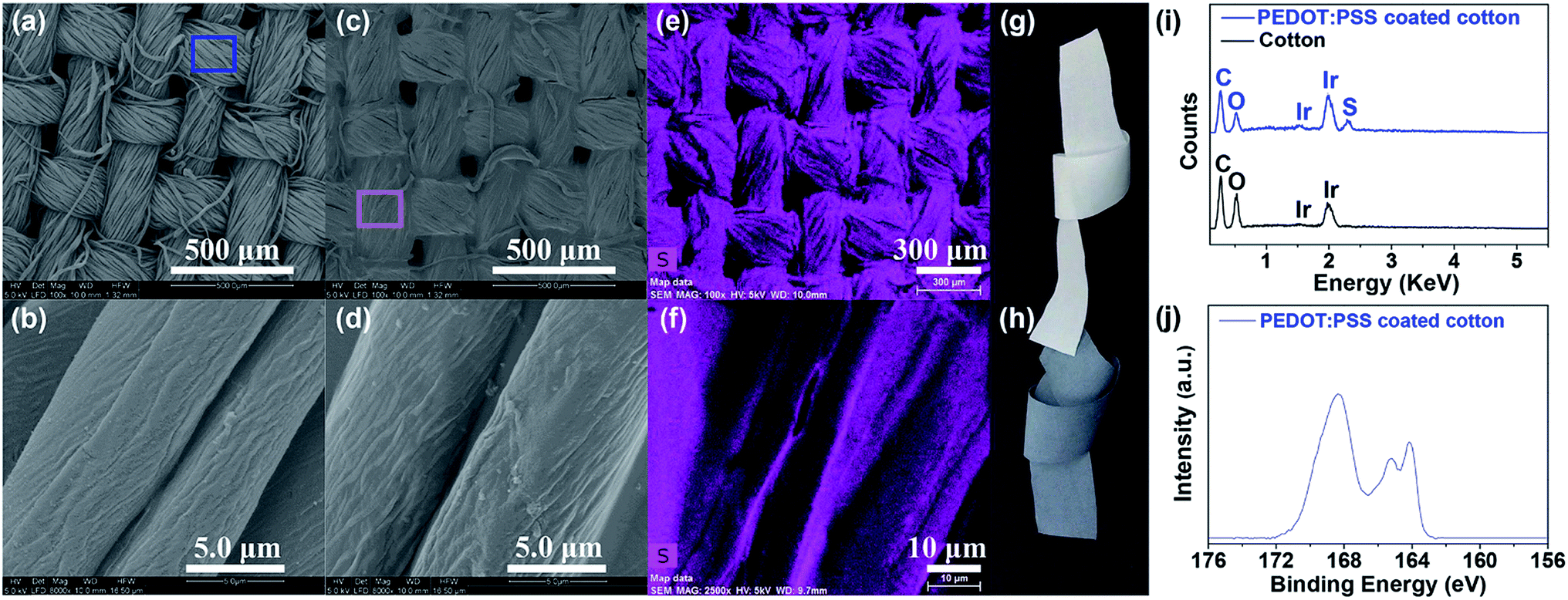 | ||
| Fig. 1 SEM images of cotton fabric (a and b) before and (c and f) after coating treatment with PEDOT:PSS. SEM-EDS mapping of the (e) PEDOT:PSS coated cotton fabric, and (f) PEDOT:PSS coated cotton fibers. Photos of commercial cotton fabric (g) before and (h) after PEDOT:PSS coating treatment. (i) EDS spectra at the areas marked by a blue square and a pink square in (a and c), respectively. (j) High resolution S 2p spectrum of PEDOT:PSS coated fabric. | ||
To confirm the chemical composition changes of the cotton fabric after PEDOT:PSS treatment, we performed an XPS analysis. Fig. 1j and ESI Fig. S5† show the XPS results of the PEDOT:PSS coated fabric. The S 2p peak at a binding energy around 168.4 eV originated from the sulfur atoms in the PSS units, whereas the peaks at around 165.2 eV and 164.2 eV corresponded the sulfur atoms in the PEDOT units.2,12,15–18 The PSS has a higher S 2p binding energy than PEDOT because the electronegative oxygen attached to the sulfonate moiety.12 The XPS result also indicates that the PEDOT:PSS is uniformly coated on the cotton fabric, which is in good agreement with the EDS and SEM-EDS mapping results.
The performance of a TE material can be expressed by a dimensionless figure of merit, ZT = S2σT/κ (where S is the Seebeck coefficient, σ is the electrical conductivity, κ is the thermal conductivity, and T is the absolute temperature).19 The electrical conductivity of the cotton fabric coated with PEDOT:PSS by this method was in the range of 0.1–3.1 S cm−1, and the Seebeck coefficient in 15.05–18.51 μV K−1 at ∼300 K. A PEDOT:PSS coated fabric was randomly chosen and cut into a small strip (length × width, ∼20.0 mm × 3.6 mm). This sample was cycled five times and the temperature dependency of their electrical conductivity, Seebeck coefficient, and calculated power factor (σS2) after each cycle is shown in Fig. 2. The electrical conductivity and Seebeck coefficient of the fabric strips exhibit very good repeatability throughout the test in the measured temperature range from 300 K to 390 K. The electrical conductivity kept almost constant throughout the range of temperatures, while the Seebeck coefficient increased slowly with an increase in temperature. As a result, the calculated power factor (based on the average value for the 5 times measurements) increased gradually from 0.049 μW m−1 K−2 at 300 K to 0.057 μW m−1 K−2 at 390 K. The PEDOT:PSS coated cotton fabrics have a positive value of Seebeck coefficient, suggesting that hole conduction is dominant.
 | ||
| Fig. 2 Dependencies of (a) electrical conductivity, (b) Seebeck coefficient, and (c) power factor of PEODT:PSS coated fabric on temperature. | ||
The TE fabric generator module was prepared by connecting the coated cotton strips (length × width, 35 mm × 5 mm for each), using Constantan wire (diameter 0.5 mm). The fabric strips were mounted to a piece of cotton fabric using silver paint (the interval of two strips is ∼5–6 mm) (see schematic illustration in Fig. 3a and ESI Fig. S6a†). To maintain the maximum temperature difference between the cold and the warm sides, the coated cotton strips were connected in series.20
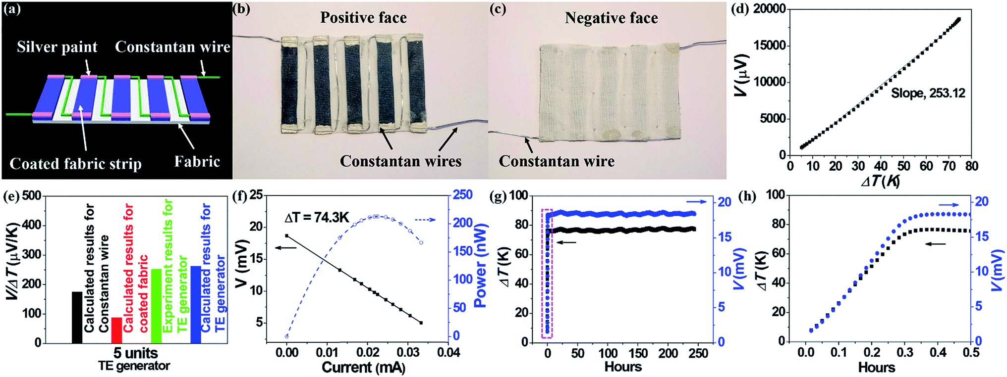 | ||
| Fig. 3 (a) Schematic illustration of the fabric-based TE generators (I-type connection). Positive (b) and negative face (c) of the 5-strip fabric-based TE generators connected with Constantan wires. (d) TE voltage generated versus ΔT, (e) the experimental results and calculated results based on eqn (1), for the TE voltage generated per 1 K ΔT (V/ΔT), and (f) the output voltage and power as a function of current (by adjusting the load resistance with different values) for the prepared 5-strip fabric-based devices connected by Constantan wires. (g) The thermal stability of the TE voltage generated by the 5-strip devices connected by Constantan wires under different time at a ΔT up to 78 K, (h) is the magnified results marked by a pink dotted line area in the (d). | ||
Such a device geometry is completely different to that of commercial inorganic TE generators. For commercial inorganic TE generators, the p-type and the n-type legs are connected in a typical π-type structure.21 This π-type connection can convert the temperature gradient between the top surface and the bottom surface of the TE legs. In our case, the PEDOT-coated fabric and metal wire were connected in series (also referred to as “I-type”, see schematic illustration in Fig. 3a and ESI Fig. S6a†), rather than a π-type (see schematic illustration in ESI Fig. S6b†).
Fig. 3b and c show the photos of positive face and negative face for the 5-strip TE generator connected by Constantan wires with I-type structure (also see positive face of the 1-unit, 3-unit, 4-unit, and 5-unit fabric-based TE generators, and negative face of the 5-unit fabric-based TE generators, connected with Constantan wires in the ESI Fig. S6c–g†). The Constantan wires were sewed along the PEDOT:PSS coated strips (Fig. 3b and c). The distance between the two fabric strips can also be adjusted as per the requirement of application. ESI Fig. S7† shows the setup to evaluate the performance of the fabric TE generator. When one side of a fabric TE generator was heated with a heater, while the other side was cooled with a chilled block, a voltage was generated.
Fig. 3d shows the voltage (V) versus temperature difference (ΔT) curves of the fabric TE generator, which consists of 5 PEDOT:PSS coated cotton strips and Constantan wires. The V increased immediately when a ΔT was applied between the two sides of the fabric generator, and the V increased linearly with an increase of the ΔT, because of the Seebeck effect. A voltage of 18.7 mV was generated at a ΔT of 74.3 K. This result indicates that a fabric-based TE generator which consists of 400 strips with Constantan wire connection could generator a V up to ∼1.5 V, which is the operating voltage for many practical devices.22 A V/ΔT of 253.12 μV K−1 was obtained for a TE generator consisting of 5 PEDOT:PSS coated fabric strips (Fig. 3d and e) and is, in part, due to the fact that the Constantan wires also contribute to the TE generation.
The V generated by our fabric TE generator can be estimated by the eqn (1):
| V = N(STE fabric − Smetal wire)·ΔT | (1) |
ESI Fig. S8a† schematically illustrates the energy conversion mechanism of our fabric TE generator. When one side of the device was heated, both of the holes in the p-type coated fabrics and electrons in the n-type Constantan wires moved from the hot side to the cooled side. As a result, the current was in the direction along the hole moving in the fabric strips, which is opposite to the electron moving in the Constantan wires. This explains why the n-type Constantan wires have a positive effect on the V of the fabric TE generator.
Fig. 3f shows the output voltage and power as a function of current (by adjusting the load resistance with different values). The voltage–current was in linear relationship and the current–power was parabolic for all the devices. As we know, when the load resistance matched the internal electrical resistance (R0) of a power generator, the power maximum (Pmax) was achieved, which can be estimated by the eqn (2)
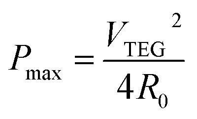 | (2) |
A Pmax of 212.6 nW was obtained at a ΔT = 74.3 K for the 5-strip TE generator.
Fig. 3g and h show the thermal stability of the fabric-based TE power generator connected by Constantan wires. The TE generator was very stable even after 10 days' non-stop run at a ΔT up to ∼78 K (Fig. 3g and h). Since the ΔT between ambient and human body (maintains at around 37 °C) is below 78 K, the fabric-based TE generator could be expected work at a wide variety of temperatures ranging from – 40 °C to 50 °C. The slight fluctuation of the output voltage was caused by the temperature control system.
The fabric-based generators were not affected by being rolled up and bent, as they still performed after being bent at different bending radii and in different directions (ESI Fig. S9 &10†). The flexible TE generator exhibited little resistance changes even after bending at different radii and directions (ESI Fig. S11†).
In addition, we also prepared TE fabric devices using silver wires as connectors (see the ESI Fig. S12a–c†). The silver wire devices showed different V and Pmax to the Constantan ones. At the same ΔT, the V increased with increasing the number of PEDOT:PSS fabric strips (N).
Table 1 and ESI Table 1† shows the comparison results of the output voltage and power for the typically flexible TE generators reported. The silver wire generator had much lower V than the Constantan wire device. The Pmax for the Constantan wire device was 17.5 times higher than that of the silver wire generator (12.16 nW at a ΔT = 72.2 K).
| Device name and methods | p-type materials | n-type materials | Number of TE legs | V | Pmax | Ref. |
|---|---|---|---|---|---|---|
| PEDOT:PSS coated polyester fabric-based generator (solution coating) | PEDOT:PSS coated polyester fabric strips connected with silver wires | 5 strips | 4.3 mV, ΔT = 75.2 K | 12.29 nW, ΔT = 75.2 K | 2 | |
| PEDOT:PSS coated cotton fabric-based generator (solution coating) | PEDOT:PSS coated cotton fabric strips connected with silver wires | 5 strips | 4.8 mV, ΔT = 70.9 K | 12.16 nW, ΔT = 72.2 K | This work | |
| PEDOT:PSS coated cotton fabric-based generator (solution coating) | PEDOT:PSS coated cotton fabric strips | Constantan wires | 5 strips | 18.7 mV, ΔT = 74.3 K | 212.6 nW, ΔT = 74.3 K | This work |
This can be attributed to the silver wire connection. Constantan is an n-type TE material, whereas silver is p-type. ESI Fig. S8b† schematically illustrates the difference in energy conversion mechanism between the two TE generators. The silver wires functioning like a p-type TE material have a deleterious effect on power generation.
Apart from the TE conversion feature, our Constantan-fabric TE generators have other unique features, such as being nontoxic, light-weight, permeable to air and moisture (even after assembling into fabric), which will be more comfortable to wear for human being than the traditional commercial TE devices.
4. Conclusions
In summary, an air-permeable and flexible TE power generator with enhanced voltage output and power was fabricated by combining PEDOT:PSS coated fabric with n-type metal wires. The device is simple to prepare and does not involve any toxic materials. The fabric generators are very stable even after 10 days' of continuous operation. They may be useful for development of self-powered wearable electronic devices.Conflicts of interest
There are no conflicts of interest to declare.Acknowledgements
This work was supported by the National Natural Science Foundation of China (61504081, 61611530550), the Program for Professor of Special Appointment (Young Eastern Scholar Program) at Shanghai Institutions of Higher Learning (QD2015039), Shanghai Innovation action plan project (17090503600), the ARC Future Fellow grant (ARC FT120100135), and the Key Program of National Natural Science Foundation of China (51632010). Alfred Deakin Postdoctoral Fellowship awarded by Deakin University to the first author is acknowledged.References
- X. Pu, L. X. Li, M. M. Liu, C. Y. Jiang, C. H. Du, Z. F. Zhao, W. G. Hu and Z. L. Wang, Adv. Mater., 2016, 28, 98 CrossRef CAS PubMed.
- Y. Du, K. F. Cai, S. Chen, H. X. Wang, S. Z. Shen, R. Donelson and T. Lin, Sci. Rep., 2015, 5, 06411 CrossRef CAS PubMed.
- J. Lee, H. J. Kim, L. F. Chen, S. H. Choi, G. N. Mathur and V. K. Varadan, Proc. SPIE, 2013, 8691, 86910R CrossRef.
- R. J. M. Vullers, R. van Schaijk, I. Doms, C. van Hoof and R. Mertens, Solid-State Electron., 2009, 53, 684 CrossRef CAS.
- Y. Du, S. Z. Shen, K. F. Cai and P. S. Casey, Prog. Polym. Sci., 2012, 37, 820 CrossRef CAS.
- Z. S. Lu, H. H. Zhang, C. P. Mao and C. M. Li, Appl. Energy, 2016, 164, 57 CrossRef CAS.
- S. J. Kim, J. H. We and B. J. Cho, Energy Environ. Sci., 2014, 7, 1959 CAS.
- M. K. Kim, M. S. Kim, S. Lee, C. Kim and Y. J. Kim, Smart Mater. Struct., 2014, 23, 105002 CrossRef.
- V. Leonov, IEEE Sens. J., 2013, 13, 2284 CrossRef.
- J. H. We, S. J. Kim and B. J. Cho, Energy, 2014, 73, 506 CrossRef CAS.
- Y. Guo, J. K. Mu, C. Y. Hou, H. Z. Wang, Q. H. Zhang and Y. G. Li, Carbon, 2016, 107, 146 CrossRef CAS.
- E. J. Bae, Y. H. Kang, K. S. Jang and S. Yun Cho, Sci. Rep., 2016, 6, 18805 CrossRef CAS PubMed.
- Y. N. Chen, Y. Zhao and Z. Q. Liang, Energy Environ. Sci., 2015, 8, 401 CAS.
- Z. Fan, P. C. Li, D. H. Du and J. Y. Ouyang, Adv. Energy Mater., 2017, 7, 1602116 CrossRef.
- G. H. Kim, L. Shao, K. Zhang and K. P. Pipe, Nat. Mater., 2013, 12, 719 CrossRef CAS PubMed.
- O. Bubnova, Z. U. Khan, A. Malti, S. Braun, M. Fahlman, M. Berggren and X. Crispin, Nat. Mater., 2011, 10, 429 CrossRef CAS PubMed.
- X. Crispin, F. L. E. Jakobsson, A. Crispin, P. C. M. Grim, P. Andersson, A. Volodin, C. van Haesendonck, M. Van der Auweraer, W. R. Salaneck and M. Berggren, Chem. Mater., 2006, 18, 4354 CrossRef CAS.
- C. C. Liu, H. Shi, J. K. Xu, Q. L. Jiang, H. J. Song and Z. Y. Zhu, J. Electron. Mater., 2015, 44, 1791 CrossRef CAS.
- K. F. Hsu, S. Loo, F. Guo, W. Chen, J. S. Dyck, C. Uher, T. Hogan, E. K. Polychroniadis and M. G. Kanatzidis, Science, 2004, 303, 818 CrossRef CAS PubMed.
- C. A. Hewitt, A. B. Kaiser, S. Roth, M. Craps, R. Czerw and D. L. Carroll, Nano Lett., 2012, 12, 1307 CrossRef CAS PubMed.
- Q. S. Wei, M. Mukaida, K. Kirihara, Y. Naitoh and T. Ishida, RSC Adv., 2014, 4, 28802 RSC.
- Y. M. Sun, P. Sheng, C. A. Di, F. Jiao, W. Xu, D. Qiu and D. B. Zhu, Adv. Mater., 2012, 24, 932 CrossRef CAS PubMed.
Footnote |
| † Electronic supplementary information (ESI) available. See DOI: 10.1039/c7ra08663f |
| This journal is © The Royal Society of Chemistry 2017 |