 Open Access Article
Creative Commons Attribution 3.0 Unported Licence
Robust Ni/WC superhydrophobic surfaces by electrodeposition†
Guochen Zhao abc,
Jinshang Lib,
Yuanfeng Huangd,
Liming Yangb,
Ying Ye
 d,
Frank C. Walshc,
Jie Chen
 *b and
Shuncai Wang
 *c
*c
aShandong Key Laboratory for High Strength Lightweight Metallic Materials, Jinan, 250000, China
bSchool of Environmental and Chemical Engineering, Shanghai University, Shanghai, 200444, China. E-mail: jchen@shu.edu.cn; Tel: +86 02166137482
cNational Centre for Advanced Tribology at Southampton (nCATS), University of Southampton, SO17 1BJ, UK. E-mail: wangs@soton.ac.uk; Tel: +44 (0)2380594638
dOcean College, Zhejiang University, 316021, China
First published on 19th September 2017
Abstract
Superhydrophobic, water repellent surfaces have attracted much attention but poor surface mechanical properties have limited their wider practical application. Robust surfaces based on nickel–tungsten carbide composite coatings have been electrodeposited. The surfaces showed superhydrophobicity after being modified by stearic acid. The maximum contact angle of water was 164.3 degrees with a sliding angle close to zero. By controlling the deposition conditions, versatile coatings have been produced and the effects of morphology on wettability are discussed. Coating texture has been analyzed by X-ray diffraction. The surfaces showed excellent abrasion resistance and water-repellence.
Introduction
Superhydrophobic surfaces, inspired by natural biology (e.g. a lotus leaf, a water strider leg or a mosquito compound eye), have drawn increasing attention from researchers and manufacturers over the last twenty years.1 Generally, a superhydrophobic surface has a water contact angle >150 degrees and a water sliding angle <10 degrees. Due to their water-repellence, such surfaces have been widely investigated in applications such as self-cleaning, anti-fogging, anti-biofouling, anti-corrosion, oil–water separation, energy saving, drag reduction, and microfluidic devices.Superhydrophobicity was first introduced in 1976 by Reick;2 its research has been accelerated after an investigation of water-repellent plants was published by Barthlott et al. in 1997.3,4 The effects of hierarchical structures on wetting was reviewed by Feng et al.5 Recently, the research on superhydrophobicity is focussed on more practical uses, and various superhydrophobic surfaces have been fabricated with improved properties. These surfaces can be classified into three categories,6 polymeric surfaces, inorganic surfaces modified by organic materials and inorganic surfaces. Due to the low surface energy of organic chemicals, most superhydrophobic surfaces are organic compounds or compounds modified by them. For instance, Tripathi et al. coated ultrathin polytetrafluoroethylene (PTFE) films on glass by RF magnetron sputtering to increase the superhydrophobicity and antireflection of the glass.7 Zhang et al. reported titanium dioxide nanowires combined with polydimethylsiloxane achieved superhydrophobicity and showed an excellent self-cleaning performance.8 Su et al. achieved the switch from superhydrophobic to hydrophilic surfaces of cobalt deposits by heating and dipping in myristic acid solution.9 Lu et al. created a superhydrophobic paint made by TiO2 nanoparticles and perfluorooctyltriethoxysilane, which has potential uses on cotton, paper, glass, and steel for self-cleaning applications.10 More and more materials have been attempted in the superhydrophobic research, like silver,11 copper,12 cobalt13 and its oxide,14 graphene,15 and silica.16 Most of these fabricated superhydrophobic surfaces, however, are at a laboratory-scale and not yet ready for robust use.17 The added surface modifiers (often fluorochemicals) tend to be environmentally persistent but are costly and easily removed by mechanical abrasion. It is clearly important to fabricate low-cost, stable and long-lasting superhydrophobic surfaces.
Nickel-based electrodeposits have played a significant role in the history of surface coating,18 with superior hardness,19–21 wear resistance,22 and corrosion resistance.23 Compared with other coating technologies, nickel-based electrodeposits have the advantages of simple setup at low cost, easy to operate, and reproducible.24 The technology of nickel electrodeposition began in the early 1900s and was optimized by Watts.25 After more than a century, this technology has become mature and routinely used for industrial production. Many superhydrophobic surfaces based on nickel electrodeposits have been reported in recent years. Khorsand et al. described a superhydrophobic nickel–cobalt alloy coating via a two-step electrodeposition without further modification.26 The coatings showed good chemical stability and long-term durability. From Khorsand's work, various nickel deposits fabricated by controlling electrodeposition parameters showed high corrosion protection and long-term durability.27 Geng et al. reported Ni micro- or nano-cone arrays fabricated by electrodeposition could be achieved following exposure to air at room temperature.28 Huang et al. prepared Ni–TiO2 composite coatings by electrodeposition, in a time saving and cost-effective fashion.29 The coatings showed superhydrophobicity after modification by FAS-17. A review published by Zhang et al. listed several nickel-based superhydrophobic surfaces which significantly enhanced boiling and condensation heat transfer performance.30 However, there were few publications which consider the abrasion resistance of electrodeposited nickel-based superhydrophobic coatings. The nickel coating deposited on copper by Su et al. became superhydrophobic after being modified by AC-FAS.31 In their abrasion test, using 800 grit SiC paper, this superhydrophobic coating could endure an abrasion length of 1000 mm under a 4.8 KPa load.
Tungsten carbide (WC) is extremely hard with a Vickers number of around 2600.32 WC is approximately two times stiffer than steel and WC–Co is the most common wear-resistance coating by thermal spray.33 The WC nanoparticles (NPs) contribute to nickel grain size reduction during codeposition while hardness and wear resistance of the composite coating are enhanced.34–36 Although the coatings have excellent wear resistance, they are intrinsically hydrophilic as the embedded WC particles in the coatings have strong covalent bonds and high surface energy.37 Therefore, developing a simple, inexpensive approach for a robust superhydrophobic surface is high required. In a recent research, Yan et al. have successfully modified the electro-brush plated Fe–TiO2 with stearic acid. However, the complex brush plating formula will affect mono the solutions' stability and thus coatings' reproducibility. Nevertheless, stearic acid (SA), a kind of fatty acid, has a long carbon–hydrogen chain and a carboxyl group on the top of the chain which determines its oil and water amphipathic property. With good lubricity and excellent stability against light and heat, stearic acid is widely used as lubrication, plasticization and stabilization, especially in PVC pipe manufacturing. Reported from previous study, stearic acid could be stable absorbed on the surface of several metals, such as gold,38 silver,39,40 copper,40 nickel,41 which indicate its application in fabrication of robust nickel-based composite coating. Liu et al. fabricated copper surfaces with dual-scale roughness by etching42 and electrodepositing43 methods. After modified by steric acid, all of the surfaces showed excellent superhydrophobicity with contact angles ranging from 167 to 170 degrees. Copper was slightly oxidized by SA indicated the SA molecular was immobilized on the surface, which decreased the surface energy.43 In addition, compared with fluorochemicals, stearic acid tends to more economical, environmentally-friendly than fluorochemicals which are the most currently used in development of hydrophobic surfaces. The inert nature of SA also benefits to maintain the surface resistance to coatings by forming inclusively a single assemble monolayer (SAM).
In the present work, a series of Ni–WC composite coatings were fabricated by electrodeposition, subsequently by a modification in a dilute stearic acid. The effects of current density, agitation speed and concentration of WC NPs in the bath will be investigated on surface morphology and wettability.
Experimental
Materials
The substrate used in this work was AISI 1020 carbon steel. Each sample was machined to the dimensions of 90 mm × 10 mm × 3 mm as cathode. The nickel plate with the same dimension was setup as anode. The bath was based on the typical Watts bath as shown in Table 1. Different concentrations of WC nanoparticles (99.9%, 400 nm, Aladdin) were added into the bath to improve the surface tribological properties of deposits. Hexadecyl trimethyl ammonium bromide (CTAB, 99%, Aladdin) as cationic surfactant was used to charge WC nanoparticles. Finally, the surface modification was processed by stearic acid (SA, AR, Aladdin). The stearic acid with its bifunctional character could be chemically adsorbed on the Ni(111) surface via a bidentate interaction.41| Component | Concentration/g dm−3 |
|---|---|
| NiSO4·6H2O (AR, Sinopharm) | 250 |
| NiCl2·6H2O (AR, Sinopharm) | 45 |
| H3BO3 (AR, Sinopharm) | 40 |
| CTAB (99%, Aladding) | 0.1 |
| WC NPs (99.9%, Aladding) | 0, 5, 10, 15, 20, 25 |
Sample preparation
Pre-treatment of the electrode surface is essential before electrodeposition. The plates were polished using 240 and 800 grit SiC sandpapers respectively. They were then rinsed in distilled water and 10% hydrochloric acid for 10 seconds to remove contaminants such as rust and oxides, and sprayed with acetone followed by distilled water.The electrodes were vertical parallel each other with an immersed area of 4 cm2 and 25 mm apart, in a 200 mL cylindrical beaker at a constant temperature of 40 °C. The solution bath was stirred by a cylindrical PTFE-coated steel magnetic follower of 6 mm diameter and 25 mm length. The deposition duration was 30 minutes.
The final process was surface modification. The as-prepared deposits were immersed into 2 mM SA–acetone solution for 60 minutes, then oven dried at 40 °C for 3 hours.
Deposit characterisation
Surface morphology was imaged by scanning electron microscopy (SEM) using a Hitachi SU-1500 instrument. The elemental analysis was carried by Oxford Instruments energy dispersive spectrometry (EDS). Wettability of the surface of coatings including water contact angle and sliding angle was analysed by an optical contact angle measuring system using EASTERN-DATAPHY OCA 15EC. The volume of water droplets was 8 μL. The angles were measured by DropSnake which is a plugin of ImageJ (software) to shape the drop.44,45 X-ray diffraction (XRD) experiments were performed on a Persee XD-3 instrument. The water bounce test utilised a Phantan V711 high speed camera at 7560 frames per second, with an approximate droplet size of 6 μL.Results and discussion
Control parameters and wettability
According to the previous theory, the wettability of solid surface is mostly determined by surface morphology and surface energy.17,46–48 The influential electrodeposition parameters, such as bath composition, additive type and level, operating conditions, agitation, cathode characters,18 should be appropriately controlled. Based on previous results,18,24,49 three factors can be identified as the dominating parameters influencing the composite electrodeposition process, namely, the particle type and concentration, the applied current density and bath agitation.50 In this work, the effects of particularly parameters have been considered, including current density, concentration and content of WC, degree of agitation. Other parameters such as temperature (40 °C), surfactant (CTAB, 0.1 g dm−3), and electrodeposition time (30 minutes) were fixed. The as-prepared coatings showed the ability to switch wettability and excellent robustness.Current density
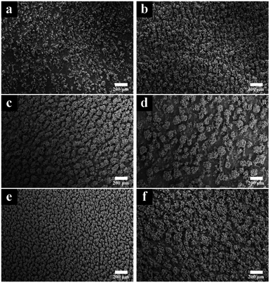
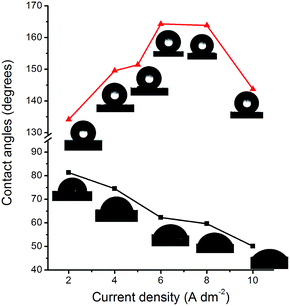
The effects of applied current density were reflected on the surface morphology. A low current density leads a low deposition rate, and a high current density results in a loose coating structure. As can be seen in Fig. 1, the roughness of the surfaces was obviously gained due to the increasing of current density, from (a) (2 A dm−2) to (f) (10 A dm−2). When 2 A dm−2 was applied, the coating showed a sparse surface. The low deposition rate caused by low current density contributed to such a structure on the smooth substrate. The locations of dendrites were random, as well as the sizes of their diameters. This phenomenon might be due to that the current density could not provide enough over potential for CTAB – WC NPs and the deposition of nickel took priority. As the current density increased (Fig. 1b–e), the appearance of cluster surface became intense. WC NPs with nickel ions were codeposited on the substrate to fabricate a uniform composite coating. The fine well-ordered dendrites were observed in Fig. 1e (8 A dm−2). The further increase of current density (10 A dm−2), however, led to a rougher surface as well as reduced tribological property (e.g. abrasive resistance) of the coating (Fig. 1f).Current density not only affects the surface morphology of coating, but also contributes in the shift of surface energy. Fig. 2 showed the influence of surface energy on wettability. For modification coatings, as the current density increased, the water contact angles decreased steadily, from 83.0 degrees (2 A dm−2) to 50.1 degrees (10 A dm−2). Two aspects may explain this trend. One is a surface roughness could enhance its original wettability. The hydrophilic surface, according to the Wenzel statement,46 is wetted faster on a rough surface than a smooth one. This is consistent with Fig. 1a–f, the rougher surfaces, the increasing hydrophilicity. The other factor is that a higher current density provides lower overpotential on the cathode, which benefits for the deposition of WC NPs. The WC contents in coatings are listed in Table 2. The increase of the nanosized WC particles will correspond to the decrease of the contact angles.
| Current density/A dm−2 | WC content/wt% |
|---|---|
| 2 | 6.8 |
| 4 | 11.5 |
| 6 | 11.9 |
| 8 | 20.1 |
After modification by SA, the coating surfaces experienced from hydrophilic to hydrophobic. As the current density increased, the hydrophobicity of modified surfaces was gradually enhanced. With the current densities of 5, 6, 8 A dm−2, the water contact angles of the surfaces reached 151.4, 164.3, 163.8 degrees, respectively, showing superhydrophobic. This switch was resulted from the passivation effect of SA. The adherent passivation layer provided heptadecyl chains exposed on the external surface and reduced the surface energy dramatically, resulting in superhydrophobicity. However, the contact angle was reduced to 143.7 degrees when at a current density of 10 A dm−2. This is probably due to the structure shown in Fig. 1f is too rough to allow water droplets penetrating51 to the surface. The results indicated that surface roughness and energy played a synergistic role in achieving a superhydrophobic surface architecture.
Concentration of WC
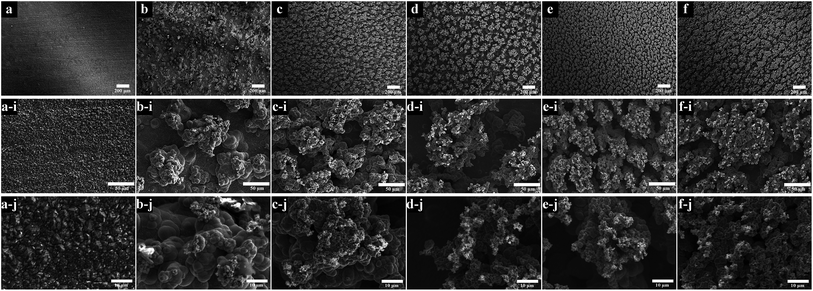
The influence of concentrations of WC on surface morphologies could be found in Fig. 3. The WC NPs were observed to reduce the grain size of nickel deposits thus improved the mechanical properties.24 The essential micro and nano structures are retained for superhydrophobicity.6 Fig. 3a shows the smooth surface of a pure nickel coating. The average grain size calculated by ImageJ from Fig. 3a-i was around 2.0 μm. As the WC NPs were increased in the bath, the grain size was reduced and dendrites (micro- and nano structures) appeared. It could be seen from Fig. 3b-i to f-i that the dendrite clusters became denser. The magnified images in Fig. 3b-j to f-j show the increasing size of dendrites. The coating fabricated from 20 g dm−3 WC NPs achieved a uniform surface in Fig. 3e, e-i and e-j. However, the further increase level of WC NPs in the bath resulted in an agglomerated micro structured coating and irregular morphological surface (Fig. 3f-i and f-j).Fig. 4a shows the contents of WC in the coatings increase with the concentration dissolved in the bath although a slight decrease is noticed for the 25 g dm−3 WC in the bath which is due to the saturated at a sufficiently high WC level as an ‘absorption effect’.52 The corresponding wettability of coatings was drawn in Fig. 4b. The figure shows that, as the WC content increased, the water contact angle increased rapidly. The superhydrophobic coatings containing 8.09, 10.27, and 20.07 wt% have the contact angles of 160.9, 161.2, and 163.8 degrees respectively. The reduced hydrophobicity of the coating which contained 18.91 wt% WC was caused by the agglomerated micro structure (Fig. 3f-i). In contrast, the smooth pure nickel coating (Fig. 3a) had a contact angle of 109.4 degrees modified by SA, demonstrating that surface roughness has a strong impact on achieving a superhydrophobic surface.
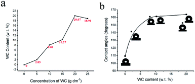 | ||
| Fig. 4 (a) The influence of concentration of WC in bath on WC content in coatings. (b) The water contact angles on coatings with different WC content. Current density was 8 A dm−2. | ||
The EDS mapping was performed in an SEM to determine the element distribution of nickel, tungsten and carbon in the micro dendrites. The tested sample (contact angle was 163.8 degrees) in Fig. 5a was fabricated from current density of 8 A dm−2, 20 g dm−3 WC NPs in bath. Fig. 5b shows nickel as the dominant element which covered the entire surface. Tungsten and carbon were mainly distributed on the top of micro dendrites which suggested the location of WC NPs.
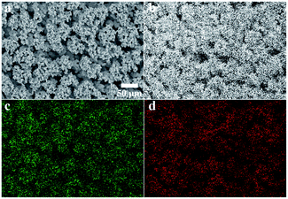 | ||
| Fig. 5 EDS mapping of the superhydrophobic coating. (a) SEM image; (b) map of element Ni; (c) map of element W; (d) map of element C. | ||
Degree of agitation
Controlled agitation is one of prerequisites to achieve uniform coatings50 although the effect of bath turbulence was complex. Fig. 6 showed the influence of three typical rotation speeds of agitation on surface morphology. In the condition of the lowest degree (400 rpm), the agglomerates were irregular and located at random, as marked by the white arrows in Fig. 6a. Some areas experienced limited co-deposition as indicated by circles. This situation was improved by increasing stirring speed. In the rates of 600 rpm in Fig. 6b and 800 rpm in Fig. 6c, the dendrites were homogenously formed and their sizes were much reduced and a directional distributed though. The particles were well-dispersed too in the coatings. The diameters of dendrites measured from Fig. 6a-i to c-i are 132.6 μm, 51.3 μm and 33.4 μm, respectively. The corresponding WC contents in the coatings were 11.9 wt%, 13.7 wt% and 22.9 wt%, which indicated the benefit to the deposition of WC NPs by increasing agitation. However, the agitation speeds seemed had little effect on the wettability of modified samples. The contact angles attached on the top right side of figures were 164.3, 161.7 and 164.0 degrees.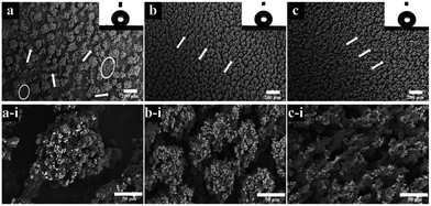 | ||
| Fig. 6 SEM images of coatings deposited with three degrees of agitation. (a) 400 rpm; (b) 600 rpm; (c) 800 rpm. (a-i), (b-i) and (c-i) were their corresponding high magnification images. | ||
Coating texture
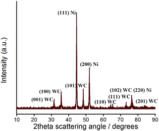
The crystal planes of coatings were identified using X-ray diffraction. Fig. 7 revealed the crystallisation on the as-prepared surfaces. The surfaces had a number of well-defined diffraction peaks. Referred to the standard diffraction of faced-cubic-centre (fcc) Ni powder (JCPDS 04-0850) and hexagonal-closed-packed WC powder (JCPDS 25-1047), three strongest peaks of Ni and WC could be found on the composite coatings (Fig. 7 spectrum III–VII), which determined the composition of structures of Ni and WC. A typical XRD pattern for the coating from a bath containing 20 g dm−3 WC is magnified in Fig. 8. The peaks of (111), (200), (220) of fcc Ni and the corresponding (001), (100), (101), (110), (111), (102), (201) of the hcp WC were indexed. Without a surprise, with the added concentrations of WC NPs increased, the diffraction peaks of WC were enhanced. This result indicated the WC contents in the coatings were steadily increased which was accorded with Fig. 4a. An evolution of preferred orientation was also observed. The pure Ni coating in spectrum II showed a strong texture of (200) plane parallel to the coating surface, compared to the maximum peak of (111) in the standard powder (Table 3). This indicates the iron matrix playing an important role for the crystal growth as the (200) plane can minimise the elastic strain. With the incorporation of the WC particles, Ni crystals in composite coatings in spectrum III–VII, however, were gradually dominated by (111) plane over other existing (200) plane. With the WC amount over 8.09%, the coatings show the close peak intensities of (111) and (200) as the standard power. The similar phenomena were also observed in Ni/WS2,53 and Ni/Al2O3 (ref. 54) composite coatings. This indicates that the addition of 8.09% WC will be enough to disturb the crystal growth, i.e. independent of the iron matrix, in which the (111) plane of fcc structure will be dominated to minimise the surface energy. The slight increase of (220) nickel peak intensities in Ni–WC deposit could be due to the spacing match less than 1% between (102)WC and (220)Ni at around 76 degrees which enhances its growth.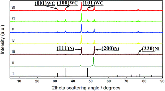 | ||
| Fig. 7 XRD patterns showing the effect of WC NPs in bath. (I) Standard XRD pattern of WC; (II) pure nickel coating; (III–VII) coatings from bath containing 5, 10, 15, 20, 25 g dm−3 WC, respectively. | ||
| hkl | Ni powder | XRD Ni peak intensities in the Ni–WC deposits with different WC contents | |||||
|---|---|---|---|---|---|---|---|
| 0% WC | 2.05% WC | 8.09% WC | 10.27% WC | 20.07% WC | 18.91% WC | ||
| 111 | 100 | 4 | 73 | 100 | 100 | 100 | 100 |
| 200 | 42 | 100 | 100 | 44 | 48 | 46 | 50 |
| 220 | 16 | 0 | 15 | 29 | 23 | 30 | 30 |
Abrasion resistance
The abrasion test was carried out on 800 grit SiC sandpaper. As shown in Fig. 9a, the as-prepared coating surface was put down on sandpaper. 100 g weight was placed on the sample to create a fixed normal pressure. The sample was moved repeatedly on the sandpaper and a return of 100 mm was recorded as 1 cycle. The whole test was carried out for more than 45 cycles, the water contact angle being measured after each cycle.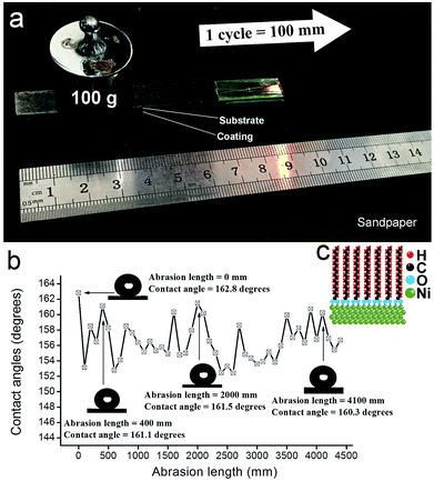 | ||
| Fig. 9 Abrasion test. (a) Setup and test procedure. (b) Influence of abrasion length on contact angles. (c) Simulation of chemical structure on the surface. | ||
Fig. 9b showed the result of abrasion test. All the contact angles were held in a range of 152 degrees to 163 degrees, which suggested that the superhydrophobicity of coating was kept during the mechanical abrasion. The contact angles were 162.8 degrees initially and then 161.1 degrees, 161.5 degrees and 160.3 degrees, after experiencing the abrasion lengths of 400 mm, 2000 mm and 4100 mm respectively. The change of water repellence property was almost imperceptible, which demonstrated the robustness of the as-prepared coatings. The abrasion length of coating kept its superhydrophobicity over 150 degrees in this work (at least 6800 mm) was longer than our published Ni/WS2 composite coating which was 1250 mm.24 The abrasive resistance of the coatings showed by Fig. 9b was similar with the “paint + adhesives” superhydrophobic surface10 (contact angles were between 156 degrees and 168 degrees in 4000 mm abrasion length) and even better than most surfaces such as AC-FAS/Ni surface31 (abrasion length was 1000 mm under a 4.8 KPa load) and organic–inorganic hybrid coatings55 (missing its superhydrophobicity after 1800 mm abrasion) etc. Two aspects contributed to the robustness of the coatings. On one hand, the incorporation of WC NPs reduced the grain size of Ni crystals, which improved mechanical property of the composite deposits, such as abrasive resistance, hardness. On the other hand, the stearic acid is chemically adsorbed on the (111)Ni surface via a bidentate interaction with a distance of approximately 1.8 Angstrom calculated by first-principles.41 As mentioned above, (111)Ni preferential crystallographic orientation was shown in the composite coating (Fig. 7). The chemical bonds (C–O–Ni) between SA and Ni deposits were formed, as illustrated by Fig. 9c. Formation of such a monolayer will maintain their superhydrophobic surface until the nickel matrix is worn out.
Water bounce studies
As an intuitive approach to determine the water repellence of the coatings, the bouncing test was carried out on the superhydrophobic surfaces. Fig. S1 in ESI† showed the snapshots acquired from time-lapse video on three as-prepared coatings. The blue water droplet in the figure was mixed with dimethyl blue. The droplet had a volume of 6 μL was dropped from a height of 60 mm above the coating. The speed when droplet touched the surface was calculated to be about 1.08 m s−1. All the samples was positioned horizontally.For a superhydrophobic or “lotus – like” surface, the water droplet would bounce with remarkable elasticity on contact. As can be seen in Fig. S1a,† the pure Ni coating with SA modified was readily wetted after touched and the droplet tended to stay on the surface to deform a stable contact angle. In contrast, the droplets in Fig. S1b and S1c† were bounced and completely left the surfaces without wetting. This meant the coatings had an excellent water-repellent property. In other words, the droplets prefer to slide down from these surfaces rather than stay on it. The water contact angles and sliding angles of these coatings are listed in Table 4.
| Current density/A dm−2 | Concentration of WC/g dm−3 | Speed of agitation/rpm | Contact angle/degrees | Sliding angle/degrees |
|---|---|---|---|---|
| 4 | 20 | 400 | 149.6 | 2.19 |
| 6 | 20 | 400 | 164.3 | 1.49 |
| 8 | 20 | 400 | 163.8 | 0.50 |
| 10 | 20 | 400 | 143.7 | 3.15 |
| 8 | 10 | 400 | 160.9 | 1.90 |
| 8 | 15 | 400 | 161.2 | 0.40 |
| 8 | 25 | 400 | 151.9 | 1.41 |
| 6 | 20 | 600 | 161.7 | 0.43 |
| 6 | 20 | 800 | 164.0 | 1.08 |
For further investigation, we introduced contact time to measure superhydrophobicity of the coatings. The contact time is how long the drop remains in contact with the surface during the shock, which depends on the inertia and capillarity of the drop, internal dissipation and surface–liquid interactions.56 Contact time could be a method to quantify the efficiency of water-repellent surfaces.57 In this work, the two coatings in Fig. S1b and S1c† had a contact time of 18.38 ms and 18.37 ms, respectively, indicating that the coatings had a similar degree of superhydrophobicity. However, the coating in Fig. S1b† (last snapshot) had a higher maximum rebound height than Fig. S1c,† probably caused by the difference in surface morphologies in Fig. 6b and 3e-i.
The videos of bouncing test could be found in Video S1, Video S2 and Video S3,† corresponding to Fig. S1a–S1c,† respectively. Interestingly, in Video S2,† a small drop was split from the big drop generated by splash, bounced higher and disappeared. In order to understand this drop, we put a group of snapshots to show its movement in ESI (Fig. S2†). Another video to demonstrate the fabrication of “lotus – like” surface by artificial rain could be found in Video S4.†. The relationship between wettability and contact time, maximum rebound height is the subject of the future work.
The surfaces switched from hydrophilic to superhydrophobic behaviour following modification by SA. The as-prepared superhydrophobic surfaces showed an excellent abrasive resistance and water-repellence.
Conclusions
By controlling electrodeposition parameters, including current density, concentration of WC NPs in the electrolyte and the degree of agitation, the as-prepared coatings achieved controlled surface morphologies. The influence of operational variables can be summarised:(a) As the current density increased, the coatings had roughness reduced. A uniform surface was observed after an 8 A dm−2 electrodeposition. Further increase of current density to 10 A dm−2 led to the surface roughness increase which reversed the surface mechanical property.
(b) The higher concentration of WC NPs in the bath resulted in a higher WC content in the coatings. A peak content on the concentration of 20 g dm−3 WC was achieved due to absorption.
(c) A well-dispersed particle content and uniform coating were fabricated using higher agitation. The intensifying agitation up to 800 rpm was observed to enhance the deposition of WC NPs.
(d) Robust superhydrophobic coatings over 160 degrees were achieved by SA modification.
(e) The embedded WC NPs reduced the textures of nickel matrix in which the crystal growth was independent of iron substrate.
(f) The abrasion test showed that the robust composite coating remained its superhydrophobic after a 4500 mm long abrasion on SiC paper. The contact angles were in the range from 152 degrees to 163 degrees but retained superhydrophobicity. The water-repellence was confirmed by a water bounce test.
Conflicts of interest
There are no conflicts to declare.Acknowledgements
The authors acknowledge financial support by the China Scholarship Council (CSC) (201406890068), the Faculty of Engineering and the Environment at University of Southampton, the Royal Society International Exchanges Scheme (IE151191), the EPSRC Global Challenge Research Fund, National Key Research and Development Plan (2016YFB0301105).References
- S. Wang, K. Liu, Y. Xi and J. Lei, Chem. Rev., 2015, 115, 705–709 Search PubMed.
- F. G. Reick, US Pat., US 3931428 A, 1976.
- C. Neinhuis and W. Barthlott, Ann. Bot., 1997, 79, 667–677 CrossRef.
- W. Barthlott and C. Neinhuis, Planta, 1997, 202, 1–8 CrossRef CAS.
- L. Feng, S. Li, Y. Li, H. Li, L. Zhang, J. Zhai, Y. Song, B. Liu, L. Jiang and D. Zhu, Adv. Mater., 2002, 14, 1857–1860 CrossRef CAS.
- F. Zhang, B. W. Robinson, H. de Villiers-Lovelock, R. J. Wood and S. C. Wang, J. Mater. Chem. A, 2015, 3, 13864–13873 CAS.
- S. Tripathi, S. M. Haque, K. D. Rao, R. De, T. Shripathi, U. Deshpande, V. Ganesan and N. K. Sahoo, Appl. Surf. Sci., 2016, 385, 289–298 CrossRef CAS.
- X. Zhang, Y. Guo, Z. Zhang and P. Zhang, Appl. Surf. Sci., 2013, 284, 319–323 CrossRef CAS.
- F. Su, K. Yao, C. Liu and P. Huang, J. Electrochem. Soc., 2013, 160, D593–D599 CrossRef CAS.
- Y. Lu, S. Sathasivam, J. Song, C. R. Crick, C. J. Carmalt and I. P. Parkin, Science, 2015, 347, 1132–1135 CrossRef CAS PubMed.
- Y. L. Zhou, M. Li, B. Su and Q. H. Lu, J. Mater. Chem. A, 2009, 19, 3301–3306 RSC.
- A. Haghdoost and R. Pitchumani, Langmuir, 2014, 30, 4183–4191 CrossRef CAS PubMed.
- Y. P. Xue, A. Taleb and P. Jegou, J. Mater. Chem. A, 2013, 1, 11580–11588 Search PubMed.
- X. Wang, W. Tian, T. Y. Zhai, C. Y. Zhi, Y. Bando and D. Golberg, J. Mater. Chem. A, 2012, 22, 23310–23326 RSC.
- X. Q. Zhang, S. H. Wan, J. B. Pu, L. P. Wang and X. Q. Liu, J. Mater. Chem. A, 2011, 21, 12251–12258 RSC.
- M. Wang, C. Chen, J. P. Ma and J. Xu, J. Mater. Chem. A, 2011, 21, 6962–6967 RSC.
- D. Zhang, L. Wang, H. Qian and X. Li, J. Coat. Technol. Res., 2016, 13, 11–29 CrossRef CAS.
- S. Wang, N. Zhou and F. C. Walsh, Trans. IMF, 2016, 94, 274–282 CrossRef CAS.
- M. Islam and M. R. Azhar, J. Mater. Eng. Perform., 2015, 24, 1–9 CrossRef.
- J. Lamovec, V. Jović, D. Randjelović, R. Aleksić and V. Radojević, Thin Solid Films, 2008, 506, 8646–8654 CrossRef.
- X. Li, Y. Gu, T. Shi and D. Peng, J. Mater. Eng. Perform., 2015, 24, 1–8 CrossRef.
- Y. He, S. C. Wang, F. C. Walsh, Y. L. Chiu and P. A. S. Reed, Surf. Coat. Technol., 2016, 307, 926–934 CrossRef CAS.
- Z. A. Hamid, M. A. Abbas and N. Gomaa, Anti-Corros. Methods Mater., 2003, 50, 115–120 CrossRef CAS.
- G. Zhao, Y. Xue, Y. Huang, Y. Ye, F. C. Walsh, J. Chen and S. C. Wang, RSC Adv., 2016, 6, 439–443 RSC.
- O. P. Watts, Trans. Am. Electrochem. Soc., 1916, 29, 395–403 Search PubMed.
- S. Khorsand, K. Raeissi, F. Ashrafizadeh and M. A. Arenas, Chem. Eng. J., 2015, 273, 638–646 CrossRef CAS.
- S. Khorsand, K. Raeissi and F. Ashrafizadeh, Appl. Surf. Sci., 2014, 305, 498–505 CrossRef CAS.
- W. Geng, A. Hu and M. Li, Appl. Surf. Sci., 2012, 263, 821–824 CrossRef CAS.
- S. Huang, Y. Hu and W. Pan, Surf. Coat. Technol., 2011, 205, 3872–3876 CrossRef CAS.
- P. Zhang and F. Lv, Energy, 2015, 82, 1068–1087 CrossRef.
- F. Su and K. Yao, ACS Appl. Mater. Interfaces, 2014, 6, 8762–8770 CAS.
- M. P. Groover, Fundamentals of modern manufacturing: materials, processes, and systems, J. Wiley, 5th edn, 2013 Search PubMed.
- R. J. K. Wood, Int. J. Refract. Met. Hard Mater., 2010, 28, 82–94 CrossRef CAS.
- S. Mohajeri, A. Dolati and S. Rezagholibeiki, Mater. Chem. Phys., 2011, 129, 746–750 CrossRef CAS.
- A. Amadeh and R. Ebadpour, J. Nanosci. Nanotechnol., 2013, 13, 1360–1363 CrossRef CAS PubMed.
- M. Stroumbouli, P. Gyftou, E. Pavlatou and N. Spyrellis, Surf. Coat. Technol., 2005, 195, 325–332 CrossRef CAS.
- N. Eustathopoulos, Metals, 2015, 5, 350 CrossRef CAS.
- J. L. Dote and R. L. Mowery, J. Phys. Chem., 1988, 92, 1571–1575 CrossRef CAS.
- A. Safaee, D. K. Sarkar and M. Farzaneh, Appl. Surf. Sci., 2008, 254, 2493–2498 CrossRef CAS.
- Y. T. Tao, J. Am. Chem. Soc., 1993, 115, 4350–4358 CrossRef CAS.
- S. H. Liang, T. Yu, D. P. Liu, W. X. Wang, Y. P. Wang and X. F. Han, J. Appl. Phys., 2011, 109, 289–295 Search PubMed.
- L. Liu, F. Xu and L. Ma, J. Phys. Chem. C, 2012, 116, 18722–18727 CAS.
- L. Liu, W. Liu, R. Chen, X. Li and X. Xie, Chem. Eng. J., 2015, 281, 804–812 CrossRef CAS.
- A. Stalder, G. Kulik, D. Sage, L. Barbieri and P. Hoffmann, Colloids Surf., A, 2006, 286, 92–103 CrossRef CAS.
- A. F. Stalder, T. Melchior, M. Müller, D. Sage, T. Blu and M. Unser, Colloids Surf., A, 2010, 364, 72–81 CrossRef CAS.
- R. N. Wenzel, Ind. Eng. Chem., 1936, 28, 988–994 CrossRef CAS.
- A. Cassie and S. Baxter, Trans. Faraday Soc., 1944, 40, 546–551 RSC.
- B. Bhushan and M. Nosonovsky, Philos. Trans. R. Soc., A, 2010, 368, 4713–4728 CrossRef CAS PubMed.
- Y. He, S. Wang, F. Walsh, W. Li, L. He and P. Reed, RSC Adv., 2015, 5, 42965–42970 RSC.
- F. Walsh and C. Ponce de Leon, Trans. IMF, 2014, 92, 83–98 CrossRef CAS.
- B. Bhushan and E. K. Her, Langmuir, 2010, 26, 8207–8217 CrossRef CAS PubMed.
- N. Guglielmi, J. Electrochem. Soc., 1972, 119, 1009–1012 CrossRef CAS.
- E. García-Lecina, I. García-Urrutia, J. Díez, J. Fornell, E. Pellicer and J. Sort, Electrochim. Acta, 2013, 114, 859–867 CrossRef.
- S. C. Wang and W. C. J. Wei, Mater. Chem. Phys., 2003, 78, 574–580 CrossRef CAS.
- H. Chang, K. Tu, X. Wang and J. Liu, RSC Adv., 2015, 5, 30647–30653 RSC.
- J. C. Bird, R. Dhiman, H.-M. Kwon and K. K. Varanasi, Nature, 2013, 503, 385–388 CrossRef CAS PubMed.
- D. Richard, C. Clanet and D. Quéré, Nature, 2002, 417, 811 CrossRef CAS PubMed.
Footnote |
| † Electronic supplementary information (ESI) available: Figures of bouncing test, videos of bouncing test and artificial rain. See DOI: 10.1039/c7ra08535d |
| This journal is © The Royal Society of Chemistry 2017 |

