
 Open Access Article
 This Open Access Article is licensed under a Creative Commons Attribution-Non Commercial 3.0 Unported Licence
An efficient polymer for producing electrospun transparent conducting films through simple procedures and a mild post-process†
Hui Chenab,
Shanyong Chen *b,
Youwei Guanb,
Hengqing Yanb,
Rong Jinb,
Huai Zhanga,
De Lia,
Jian Zhong*a and
Lu Li*b
*b,
Youwei Guanb,
Hengqing Yanb,
Rong Jinb,
Huai Zhanga,
De Lia,
Jian Zhong*a and
Lu Li*b
aState Key Laboratory of Electronic Thin Films and Integrated Devices, School of Optoelectronic Information, University of Electronic Science and Technology of China (UESTC), Chengdu 610054, P. R. China. E-mail: zhongjian@uestc.edu.cn
bResearch Institute for New Materials Technology, Chongqing University of Arts and Sciences, Yongchuan 402160, P. R. China. E-mail: jluchensy@163.com; lli@cqwu.edu.cn
First published on 3rd October 2017
Abstract
As a particular method for the preparation of metal-nanowire-based transparent conducting films (TCFs), electrospinning has some advantages that common methods don't possess, such as a low requirement for the match of substrate, no coffee rings and the ability of preparing films on curved or rugged substrates. However, at present, complex preparation procedures or high temperature treatment are usually needed to prevent electrospinning polymers from affecting the performance of TCFs. To solve this problem, polymers that are suitable for direct electrospinning with metal nanowires and can be easily eliminated under mild conditions are desirable. However, this type of polymer has been rarely reported. In this study, silver nanowires (AgNWs) were selected as the representative of metal nanowires and different polymers were tried to discover the most suitable material. The results of the experiments indicated that polyethylene oxide (PEO) (Mw = 50![[thin space (1/6-em)]](https://www.rsc.org/images/entities/char_2009.gif) 000) was the most suitable polymer. The chain length of this polymer was enough to effectively wrap the AgNWs to obtain good electrospinning films and it could be easily eliminated under mild conditions because of its low melting point and excellent solubility. Then, we determined the most suitable electrospinning solution, which consists of AgNWs (0.3%), PEO (2.5%), AMP (0.2%) and DI water (97%). From this solution, uniform electrospinning films were prepared. Subsequently, this film was heated at 70 °C for 15 s to fasten the AgNWs onto the substrate and then soaked in ethanol (70 °C) for 10 s to eliminate PEO, in sequence. Finally, a good TCF was obtained. The sheet resistance and transmittance of this film were 94 Ω sq−1 and 83.4%, respectively.
000) was the most suitable polymer. The chain length of this polymer was enough to effectively wrap the AgNWs to obtain good electrospinning films and it could be easily eliminated under mild conditions because of its low melting point and excellent solubility. Then, we determined the most suitable electrospinning solution, which consists of AgNWs (0.3%), PEO (2.5%), AMP (0.2%) and DI water (97%). From this solution, uniform electrospinning films were prepared. Subsequently, this film was heated at 70 °C for 15 s to fasten the AgNWs onto the substrate and then soaked in ethanol (70 °C) for 10 s to eliminate PEO, in sequence. Finally, a good TCF was obtained. The sheet resistance and transmittance of this film were 94 Ω sq−1 and 83.4%, respectively.
Introduction
Due to the wide application in transparent conducting films (TCFs), metal nanowires have gained a lot of attention over the last decade.1 At present, researchers usually prepare metal-nanowire-based TCFs through the following methods: spin coating,2 roller coating3 and roll-to-roll printing,4 which are suitable for the preparation of small-scale films, full-scale films and industrial production, respectively. These methods are simple and can produce excellent TCFs. However, these common methods have some intrinsic drawbacks. First, researchers should spend a great deal of time to adjust the kinetic properties of the metal nanowire inks, which is challenging. To prepare uniform films, metal nanowire inks must simultaneously have good matching with the substrates, machines and processing technologies. Generally, for one specific substrate and machine, only one specific ink has the best match. If the substrate or machine has some changes, the ink must be adjusted again. The adjustment process needs a lot of experiments and a great deal of time. In earnest, adjustment of the kinetic properties of inks is the core secret of ink companies and there are almost no reports available to teach the same to researchers. Therefore, it is difficult for researchers to obtain inks with the most suitable kinetic properties and this will greatly affect the uniformity of the films. Second, these three methods are not suitable for some types of metal nanowires. For copper nanowires (CuNWs) and gold nanowires (AuNW), researchers are unable to prepare qualified inks from them at present. However, metal nanowire inks are necessary materials to prepare TCFs through these three methods. Therefore, it is difficult to prepare uniform large-scale CuNW/AuNW-based TCFs through these three methods at present.5 Third, through these three methods, researchers can prepare TCFs on flat substrates, but could not prepare TCFs on curved or rugged substrates, which also have many applications.To improve the abovementioned problems, electrospinning is introduced because of its fascinating characteristics.6 First, for different substrates, the electrospinning solutions can be the same, which avoids the painful adjustment process of inks. Second, coffee rings or punctate films often exist during the preparation process of TCFs using inks.7 In contrast, during the electrospinning process, the fibers are dry when they fall on the substrate. Therefore, coffee rings and punctate films do not exist and uniform TCFs can be obtained easily through electrospinning. Third, electrospinning polymers could stabilize the CuNWs or AuNWs for their effective dispersion. Hence, large-scale CuNW/AuNW-based TCFs could be obtained through this method. Fourth, by using multi-needles and adjusting the position of each needle, researchers can prepare uniform TCFs on curving or rugged substrates through electrospinning. Because of these advantages, several researchers have chosen electrospinning to prepare TCFs.8 On the whole, the present preparation procedures that researchers utilize can be divided into three types: (1) polymer fibers are prepared by electrospinning and then, the metals are deposited onto the surface of the fibers via electroplating,9 sputtering10,11 or chemical deposition;12 (2) polymer fibers, which contain metal precursors are prepared by electrospinning and then, the polymers are eliminated and the metal precursors decompose into metal nanomaterials under high temperature13–15 or UV light;16 (3) the metals are deposited onto the substrate and then the polymer fibers are prepared by electrospinning on the surface of the metal layer; subsequently, the metal areas that are not covered by the fibers are etched and finally the fibers are eliminated by heat or solvent to obtain the TCFs.17,18 Using the abovementioned procedures, many excellent TCFs have been prepared.19
However, electrospinning is just one step in these procedures and two or more additional steps are usually required, which reveals the complexity of these procedures. Why do researchers utilize complex procedures and why don't they prepare TCFs using electrospinning directly? This question involves the principle of electrospinning. Electrospinning needs polymers to form fibers. Therefore, polymers are essential materials for electrospinning. At present, polyacrylonitrile (PAN),20 poly(vinyl alcohol) (PVA),21,22 polyvinylpyrrolidone (PVP),23,24 poly(acrylic acid) (PAA)8 and polystyrene (PS)25 are the most commonly used polymers used in electrospinning. These materials can form outstanding fibers but are difficult to be eliminated under mild conditions. If metal nanowires and these polymers mix together to prepare electrospun films, the existence of polymers will make the films non-conductive. To avoid the influence of the polymers, researchers have to use complex procedures or eliminate the polymers under extreme conditions.14 To prepare electrospun TCFs through simple procedures and a mild post-process, polymers which can be easily eliminated under mild conditions are necessary. However, such types of polymers have been rarely reported.
To solve this problem, in this study, silver nanowires (AgNWs) were chosen as a representative of metal nanowires. Different types of polymers and polymers with different molecular weights were investigated to find out the most suitable polymer for direct electrospinning with AgNWs. Then, the most appropriate concentrations of stabilizer, polymer and AgNWs in the electrospinning solution were determined. Finally, the TCF prepared from this solution was studied (Scheme 1).
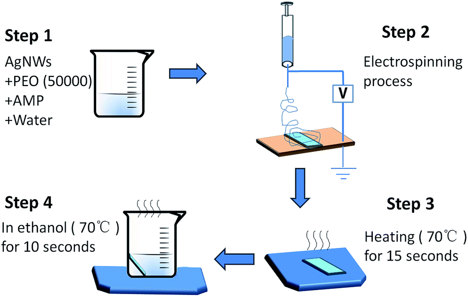 | ||
| Scheme 1 The preparation procedure of the electrospun TCFs based on PEO (Mw = 50000). | ||
Results and discussion
Preparation of the AgNWs
AgNWs were prepared according to a method reported in literature.26 The results of X-ray diffraction (XRD, Fig. S1, ESI†) and energy dispersive spectroscopy (EDS) analyses (Fig. S2, ESI†) demonstrated that pure AgNWs were obtained. The SEM image of the AgNWs exhibited their diameters ranging from 35 to 55 nm and their length ranging from 5.2 to 26.3 μm (Fig. 1).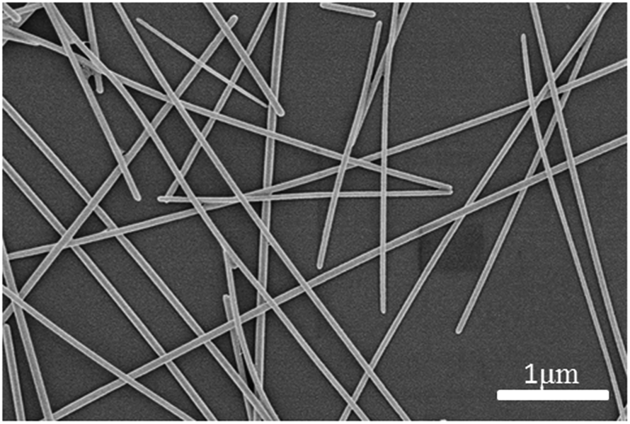 | ||
| Fig. 1 The SEM image of the AgNWs used in our experiments. | ||
Determination of the suitable polymer
As discussed above, to simplify present preparation procedures through electrospinning, we should first determine a suitable polymer. To realize this purpose, different polymers were introduced. For comparison, the concentrations of the polymers (2.0%), AMP (0.2%), AgNW (0.2%) and DI water (97.6%) in the electrospinning solutions were fixed.At present, polyvinylpyrrolidone (PVP) and poly(vinyl alcohol) (PVA) are the most commonly used polymers in electrospinning. Therefore, PVP (Mw = 55000, 360000, 1300000) and PVA were initially introduced. After electrospinning, uniform films were obtained, which indicated that PVP and PVA were highly suitable for electrospinning. However, PVP and PVA were not suitable for direct electrospinning with AgNWs because it was difficult to eliminate them under mild conditions. After the films were immersed in water (70°), PVP or PVA dissolved slowly. With the dissolution of polymers, the AgNWs also gradually dispersed in water. When the polymers dissolved in water completely, there were almost no AgNWs on the surface of the glass slide.
To improve this situation, polyvinyl acetate (PVAc) was introduced because of its lower melting point than those of PVP and PVA. After electrospinning, the film was placed on a hot stage (110 °C). Consequently, PVAc melted and the inner AgNWs were exposed. Part of the AgNWs could be fastened by the glass slide. In comparison, PVP and PVA did not melt and the AgNWs were still wrapped by the polymers. Although PVAc brought about some improvement, with the dissolution of PVAc in ethanol (70 °C), most of the AgNWs also dispersed in ethanol and the final film was non-conducting.
From the abovementioned experiments, we discovered that the polymers suitable for direct electrospinning with AgNWs should have low melting points and excellent solubilities in the solvent used simultaneously. If the polymer has a low melting point but poor solubility, the solvent needs a lot of time to dissolve the polymer. The glass slide can fasten the AgNWs in a short time, but is unable to hold them for a long time during the polymer dissolution. Consequently, the AgNWs fastened by the glass will gradually fall off and disperse in the solvent. The increase in duration for polymer dissolution will lead to large amount of AgNWs dispersion in the solvent; eventually, the residual AgNWs on the glass slide will be insufficient for the formation of a conductive network and the final TCF will be non-conductive. If the polymer has excellent solubility and a high melting point, high temperature is required for melting the polymer. It is well known that if an AgNW-based TCF is treated at high temperature, its lifetime will be short. Such films are not suitable for practical applications. Hence, PEO was introduced because it met these two requirements. The melting point of PEO is about 65 °C and it could dissolve easily in water or alcohol solvent. Except for this type of polymer, the molecular weight of PEO should also be considered because of the following two reasons. First, to obtain uniform films, the AgNWs need PEO with enough chain length to wrap it. Second, as a type of flocculant, the molecular weight of PEO will affect the stability of the electrospinning solution, which has a compact relationship with the uniformity of the final electrospun films. PEO is an electron-withdrawing polymer that would absorb the surface charge of the AgNWs. The decrease in the surface charge would weaken the repulsive force between the AgNWs, resulting in flocculation. With an increase in the molecular weight of PEO, the electron-withdrawing abilities of PEO were enhanced and the flocculation phenomenon of the electrospinning solution was more evident.
To investigate the abovementioned influences, PEO with different molecular weights (Mw = 8000, 20000, 30000, 50000, 100000, 300000, 500000 and 1000000) were used. The results of the experiments indicated that PEO with higher molecular weights (≥100000) enabled the flocculation of AgNWs in the electrospinning solution and brought about very poor uniformity for the final electrospinning films. When PEO with a low molecular weight (≤30000) was used, no flocculation occurred. However, this type of PEO could not effectively wrap the AgNWs and punctate films were obtained after electrospinning. Finally, PEO (Mw = 50000) was used because no evident flocculation was observed in the electrospinning solution on the addition of this polymer and the chain length of this polymer was enough to effectively wrap the AgNWs. In addition, uniform electrospinning films were obtained using this polymer. Furthermore, we investigated the relationship between the flocculation phenomenon and the concentration of PEO with different molecular weights (Mw = 20000, 30000, 50000 and 100000). The results of the experiments indicated that the molecular weight of PEO played a key role in the flocculation of the electrospinning solutions and the concentrations of PEO had little influence. Therefore, PEO (Mw = 50000) was suitable for the direct electrospinning with the AgNWs.
Although PEO (Mw = 50000) didn't bring about evident flocculation, it still absorbed some surface charge of the AgNWs. Before the addition of PEO (Mw = 50000), the zeta potential of the AgNWs was −43.48 mV. After the addition of PEO (Mw = 50000), the zeta potential decreased to −0.83 mV. To improve the dispersion uniformity of the AgNWs in the electrospinning solution and then increase the uniformity of the films, the surface charge of the AgNWs should be enhanced. Two methods are usually used to realize this purpose: introduction of steric effect and formation of electric double layer (EDL). For the steric effect, the polymers are adsorbed onto the surface of the AgNWs to form protective layers that can prevent the aggregation of the AgNWs. However, these polymers usually do not dissolve in the solvent quickly. This is highly unfavorable for the post-process of electrospun films. When compared with the steric effect, EDL mechanism depends on the electrostatic repulsion to stabilize AgNWs and the zeta potential represents the magnitude of the repulsive forces. The definition of the zeta potential is described in Fig. S3 and Page S3.† A higher zeta potential leads to higher repulsive forces that can bring about the higher dispersion stability of the AgNWs.
Many types of factors can affect the zeta potential. Among these factors, the pH is the most important factor for the zeta potential because a small variation in the pH may bring about a drastic change in the surface charge of the AgNWs. Therefore, factors that could modify the pH of the electrospinning solution could also be utilized to stabilize the AgNWs. According to our previous study,27 2-amino-2-methyl-1-propanol (AMP) was used an efficient pH modifier (alkalinity). Hence, in this study, AMP was chosen to adjust the surface charge of the AgNWs. With an increase in the amount of AMP, the pH and conductivity of the electrospinning solution increased. This had been verified by our previous study.27 The increase in pH could make the surface of the AgNWs have a more negative charge, which would bring about a higher zeta potential. In contrast, the increase in conductivity could compress the electric double layer, which would decrease the zeta potential. The final zeta potential was determined by the competition of these two factors and the highest zeta potential often existed at the balance point of these two factors.
To determine this balance point, different concentrations (0.0, 0.1, 0.15, 0.20, 0.25, 0.30, 0.40, 0.50 and 0.60%) of AMP were used to study its influence on the surface charge of the AgNWs while the concentrations of the AgNWs (0.01%) and PEO (2%) were fixed (Fig. 2). From 0% to 0.2% of AMP, the zeta potential of the AgNWs increased from −0.83 to −2.86 mV, which indicated that the surface charge of the AgNWs was enhanced. From 0.2% to 0.6%, the zeta potential decreased from −2.86 to −1.54 mV. The highest zeta potential (−2.86 mV) was achieved at a concentration of 0.2%. Therefore, AMP at a concentration of 0.2% was used to stabilize the AgNWs in the electrospinning solution.
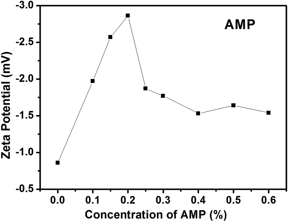 | ||
| Fig. 2 The zeta potentials of the electrospinning solutions with different concentrations (0.0, 0.1, 0.15, 0.2, 0.25, 0.3, 0.4, 0.5 and 0.6%) of AMP. | ||
Determination of the concentration of PEO
From the abovementioned experiments, PEO (Mw = 50000) was determined to be the most suitable polymer. Following this, we studied the preparation of good TCFs through electrospinning. The concentration of PEO in the electrospinning solution had a great influence on the performance of the final TCFs. A low concentration of PEO did not provide enough molecules to wrap all the AgNWs, which would lower the distribution uniformity of the AgNWs in the electrospinning films. Although a high concentration of PEO could effectively wrap all the AgNWs to obtain uniform electrospinning films, excessive concentration of the polymer was adverse for the performance of the final films. Therefore, to obtain good TCFs, we should first determine the optimum concentration of PEO.
For this purpose, electrospinning solutions with different concentrations (1.0, 1.5, 2.0, 2.5 and 3.0%) of PEO, but the same concentrations of AgNWs (0.2%) and AMP (0.2%) were prepared. Then, the TCFs were fabricated from these solutions. The sheet resistances and transmittances of the TCFs were measured. The relationship between the concentration of PEO and the performance of the TCFs is shown in Fig. 3, 4 and Table 1. As the concentration of PEO was altered from 1% to 2.5%, the sheet resistances of the films gradually decreased from 360 Ω sq−1 to 180 Ω sq−1, while the transmittances of the films gradually increased from 80.3% to 86.0%. In contrast, as the concentration of PEO altered from 2.5% to 3%, the sheet resistances of the films increased from 180 Ω sq−1 to 250 Ω sq−1, while the transmittances of the films decreased from 86.0% to 78.5%. Clearly, for PEO at a concentration of 2.5%, the best TCF was obtained. Therefore, PEO at the concentration of 2.5% was utilized for direct electrospinning with the AgNWs.
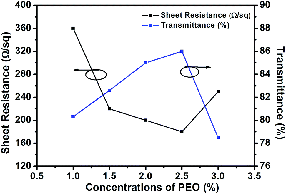 | ||
| Fig. 3 Comparison of the electrical and optical properties (at 550 nm) of the films prepared from the electrospinning solutions with different concentrations (1.0, 1.5, 2.0, 2.5 and 3.0%) of PEO. | ||
 | ||
| Fig. 4 The transmission spectra of the TCFs prepared from the electrospinning solutions with different concentrations (1.0, 1.5, 2.0, 2.5 and 3.0%) of PEO. | ||
| Concentrations of PEO (%) | Sheet resistance (Ω sq−1) | Transmittance (%) |
|---|---|---|
| 1.0 | 360 | 80.3 |
| 1.5 | 220 | 82.6 |
| 2.0 | 200 | 85.0 |
| 2.5 | 180 | 86.0 |
| 3.0 | 250 | 78.5 |
Determination of the concentration of the AgNWs
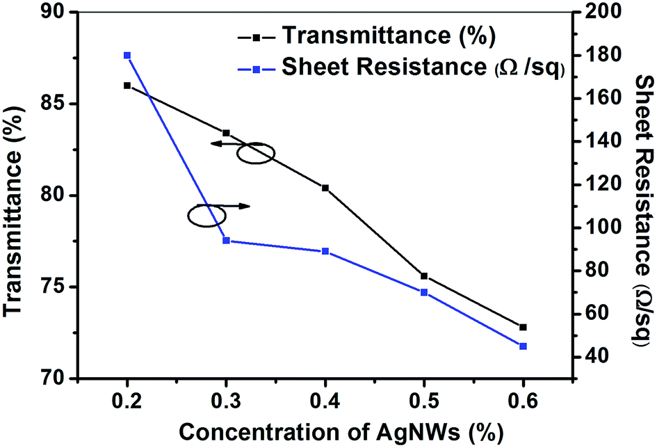
Based on the abovementioned experiments, we determined the best concentration of PEO in the electrospinning solution. However, the sheet resistance of the best TCF was 180 Ω sq−1, which didn't meet the requirements of practical applications. Therefore, we adjusted the concentration of the AgNWs to obtain qualified conductivity for the final film.To realize the abovementioned goal, we first prepared electrospinning solutions with different concentrations of the AgNWs (0.1, 0.2, 0.3, 0.4, 0.5 and 0.6%), but with the same concentrations of PEO (2.5%) and AMP (0.2%). Then, the TCFs were fabricated from these solutions. The sheet resistances and transmittances of the TCFs were measured. The relationship between the concentration of the AgNWs and the performance of the TCFs is shown in Fig. 5, 6 and Table 2. With an increase in the concentration of the AgNWs, the sheet resistances and transmittances of the TCFs decreased (Fig. 5 and 6). At AgNWs concentrations of 0.1%, 0.2%, 0.3%, 0.4%, 0.5% and 0.6%, the sheet resistances were 5 × 10⁶, 180, 94, 89, 70 and 45 Ω sq−1, respectively, while the transmittances (at 550 nm) were 87.7%, 86.0%, 83.4%, 80.4%, 75.6% and 72.8%, respectively (Table 2).
 | ||
| Fig. 5 The transmission spectra of the TCFs prepared from the electrospinning solutions with different concentrations (0.1, 0.2, 0.3, 0.4, 0.5 and 0.6%) of the AgNWs. | ||
 | ||
| Fig. 6 The sheet resistances and transmittances (at 550 nm) of the TCFs prepared from the electrospinning solutions with different concentrations (0.2, 0.3, 0.4, 0.5 and 0.6%) of the AgNWs. | ||
| Concentrations of AgNWs (%) | Sheet resistance (Ω sq−1) | Transmittance (%) | FoM (×10−4) |
|---|---|---|---|
| 0.1 | 5 × 10⁶ | 87.7 | 5.38 × 10⁻⁴ |
| 0.2 | 180 | 86.0 | 12.29 |
| 0.3 | 94 | 83.4 | 17.32 |
| 0.4 | 89 | 80.4 | 12.68 |
| 0.5 | 70 | 75.6 | 8.71 |
| 0.6 | 45 | 72.8 | 9.29 |
Clearly, with an increase in the conductivity, the transmittance decreased. To balance the sheet resistance and transmittance, the figure of merit (FoM) is often used for evaluation.28,29 Generally, a higher FoM means a better performance of the TCF. The FoM calculation formula is defined as follows:28–30
| FoM = T10/Rs |
Performance of the final TCF
From the abovementioned experiments, we determined a suitable polymer for direct electrospinning with AgNWs. Then, the most suitable electrospinning solution was also determined and was comprised of AgNWs (0.3%), PEO (2.5%), AMP (0.2%) and DI H2O (97%). Through optimization of the processing technology, a good TCF was obtained. The AgNWs were distributed uniformly in this TCF (Fig. 7a). The sheet resistance and transmittance of this TCF were 94 Ω sq−1 and 83.4% (at 550 nm), respectively (Fig. 7). The conductivity of the entire film was verified using a bulb experiment (Fig. 8).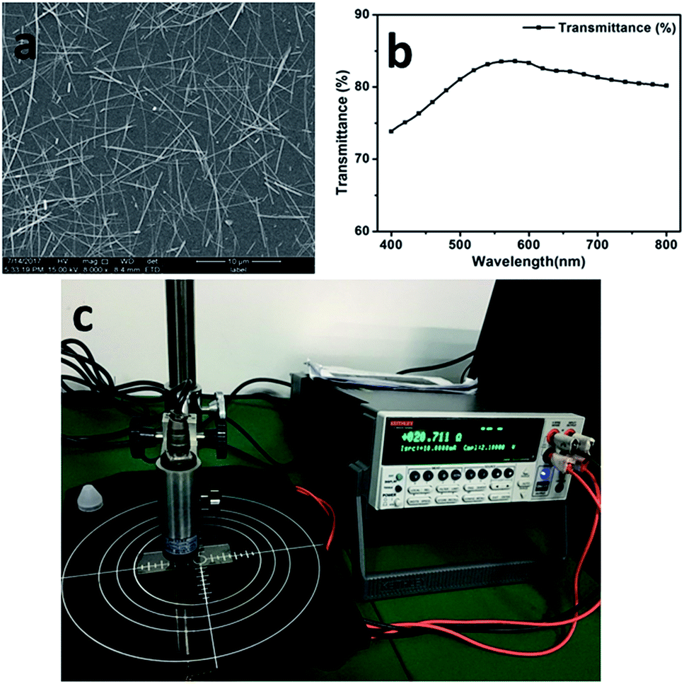 | ||
| Fig. 7 (a) The SEM image of the AgNWs in the final electrospun film, (b) the transmission spectra of the final film and (c) the sheet resistance (×4.532) of the final film. | ||
 | ||
| Fig. 8 The bulb experiment, which verified the conductivity of the whole film. | ||
Conclusions
In summary, a polymer suitable for direct electrospinning with AgNWs, PEO (Mw = 50000), has been introduced in this study. Based on this polymer, a suitable electrospinning solution was developed and consisted of AgNWs (0.3%), PEO (2.5%), AMP (0.2%) and DI H2O (97%). PEO endowed this solution with good electrospinning properties, and uniform electrospinning films were prepared from this solution. In particular, because of its low melting point and excellent solubility, PEO could be easily eliminated from this electrospinning film under mild conditions and a good TCF was obtained. The sheet resistance and transmittance of the final film were 94 Ω sq−1 and 83.4%, respectively. At present, such a polymer is rarely reported. Our study presents an efficient polymer to simplify the present complex preparation procedures of TCFs using electrospinning and the development of TCFs with much better performance is ongoing in our laboratory.
Experimental section
General information
000, 360000, 1300000), poly(vinyl alcohol) (PVA) and polyvinyl acetate (PVAc) were purchased from Sigma-Aldrich. Silver nitrate, 2-amino-2-methyl-1-propanol (AMP) and sodium bromide were obtained from Energy Chemical. Ethylene glycol (EG), acetone and ethanol were purchased from Kelong Chemical. PEO (Mw = 8000, 20000, 40000, 50000, 100000, 300000, 500000 and 1000000) was purchased from Ryoji Organic Chemical. The glass slide was obtained from Sail Brand Company.000) and 0.08 g of PVP (Mw = 360000) were dissolved in EG (22 mL) at 140 °C. Further, 2.5 mL of FeCl3 solution (600 μM in EG) and AgNO3 solution (0.180 g in 3 mL of EG) were added to the mixed solution within 1 min, in sequence. The reaction was performed at 140 °C for 50 min. Upon completion of the reaction, the mixture was cooled to room temperature. Finally, the mixture was washed with ethanol and centrifuged. The purification process was repeated 3 times. A final dispersion of AgNWs in water was obtained.000) + x% AMP (x = 0.0, 0.1, 0.15, 0.20, 0.25, 0.30, 0.40, 0.50 and 0.60%) + (97.99 − x)% H2O. Every sample was measured five times and the average value was used as the zeta potential of this sample.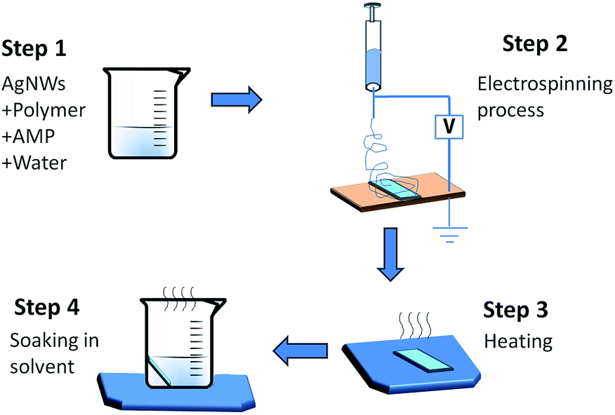 | ||
| Scheme 2 The preparation procedure of the electrospun TCFs. | ||
000, 360000, 1300000), poly(vinyl alcohol) (PVA), polyvinyl acetate (PVAc) and PEO (Mw = 8000, 20000, 40000, 50000, 100000, 300000, 500000 and 1000000) were the polymers used in our experiments. To determine the most suitable polymer, the electrospinning solutions consisted of polymer (2.0%), AMP (0.2%), AgNWs (0.2%) and water (97.6%). To determine the most appropriate concentrations of PEO, electrospinning solutions with different concentrations of PEO (1.0, 1.5, 2.0, 2.5 and 3.0%), but the same concentrations of AgNWs (0.2%) and AMP (0.2%) were prepared. To determine the most appropriate concentrations of the AgNWs, electrospinning solutions with different concentrations (0.1, 0.2, 0.3, 0.4, 0.5 and 0.6%) of AgNWs, but the same concentrations of PEO (2.5%) and AMP (0.2%) were prepared.Every electrospinning solution was used to prepare the TCFs five times to ensure that the performance of the representative TCF could be repeated. Each time six electrospun films were generated. After measuring the performance of these films, the films with the best performance were chosen.
Conflicts of interest
There are no conflicts to declare.Acknowledgements
The authors thank the International S&T Cooperation Program of China (2014DFR50830), the Scientific and Technological Research Program of Chongqing Municipal Education Commission (KJ1501117, KJ1601106, KJ1401122), the Talent Introduction Project of Chongqing University of Arts and Sciences (R2014CJ03, R2013CJ09), the National Natural Science Foundation of China (51503022), the Open Foundation of State Key Laboratory of Electronic Thin Films and Integrated Devices (KFJJ201507), the Basic and Frontier Research Program of Chongqing Municipality (cstc2015jcyjA50036, cstc2017jcyjAX0163) and the Natural Science Foundation of Yongchuan District (Ycstc, 2015nc4001) and the General Project of Chongqing University of Arts and Sciences (Y2015XC30) for financial support.Notes and references
- S. Chen, Y. Li, R. Jin, Y. Guan, H. Ni, Q. Wan and L. Li, J. Alloys Compd., 2017, 706, 164–175 CrossRef CAS.
- H. Lu, D. Zhang, J. Cheng, J. Liu, J. Mao and W. C. H. Choy, Adv. Funct. Mater., 2015, 25, 4211–4218 CrossRef CAS.
- D. Chen, J. Liang, C. Liu, G. Saldanha, F. Zhao, K. Tong, J. Liu and Q. Pei, Adv. Funct. Mater., 2015, 25, 7512–7520 CrossRef.
- D. Angmo, T. R. Andersen, J. J. Bentzen, M. Helgesen, R. R. Sondergaard, M. Jorgensen, J. E. Carle, E. Bundgaard and F. C. Krebs, Adv. Funct. Mater., 2015, 25, 4539–4547 CrossRef CAS.
- S. Han, S. Hong, J. Ham, J. Yeo, J. Lee, B. Kang, P. Lee, J. Kwon, S. S. Lee, M.-Y. Yang and S. H. Ko, Adv. Mater., 2014, 26, 5808–5814 CrossRef CAS PubMed.
- S. Ji, J. Jang, E. Cho, S.-H. Kim, E.-S. Kang, J. Kim, H.-K. Kim, H. Kong, S.-K. Kim, J.-Y. Kim and J.-U. Park, Adv. Mater., 2017, 29, 1700538 CrossRef PubMed.
- W. Zhou, A. Hu, S. Bai, Y. Ma and D. Bridges, RSC Adv., 2015, 5, 39103–39109 RSC.
- W. Jia, Y. Wang, J. Basu, T. Strout, C. B. Carter, A. Gokirmak and Y. Lei, J. Phys. Chem. C, 2009, 113, 19525–19530 CAS.
- S. An, I. Y. Kim, S. Sinha-Ray, M.-W. Kim, H. S. Jo, M. T. Swihart, A. L. Yarin and S. S. Yoon, Nanoscale, 2017, 9, 6076–6084 RSC.
- S. B. Singh, Y. Hu, T. Kshetri, N. H. Kim and J. H. Lee, J. Mater. Chem. C, 2017, 5, 4198–4205 RSC.
- H. Wu, D. Kong, Z. Ruan, P.-C. Hsu, S. Wang, Z. Yu, T. J. Carney, L. Hu, S. Fan and Y. Cui, Nat. Nanotechnol., 2013, 8, 421–425 CrossRef CAS PubMed.
- P.-C. Hsu, D. Kong, S. Wang, H. Wang, A. J. Welch, H. Wu and Y. Cui, J. Am. Chem. Soc., 2014, 136, 10593–10596 CrossRef CAS PubMed.
- Y.-Y. Cho and C. Kuo, J. Mater. Chem. C, 2016, 4, 7649–7657 RSC.
- P.-C. Hsu, H. Wu, T. J. Carney, M. T. McDowell, Y. Yang, E. C. Garnett, M. Li, L. Hu and Y. Cui, ACS Nano, 2012, 6, 5150–5156 CrossRef CAS PubMed.
- Y. Huang, X. Bai, M. Zhou, S. Liao, Z. Yu, Y. Wang and H. Wu, Nano Lett., 2016, 16, 5846–5851 CrossRef CAS PubMed.
- H.-T. Chen, H.-L. Lin, C. Kuo and I.-G. Chen, J. Mater. Chem. C, 2016, 4, 7675–7682 RSC.
- T. He, A. Xie, D. H. Reneker and Y. Zhu, ACS Nano, 2014, 8, 4782–4789 CrossRef CAS PubMed.
- K. Azuma, K. Sakajiri, H. Matsumoto, S. Kang, J. Watanabe and M. Tokita, Mater. Lett., 2014, 115, 187–189 CrossRef CAS.
- S.-Y. Min, Y. Lee, S. H. Kim, C. Park and T.-W. Lee, ACS Nano, 2017, 11, 3681–3689 CrossRef CAS PubMed.
- S. Soltanian, R. Rahmanian, B. Gholamkhass, N. M. Kiasari, F. Ko and P. Servati, Adv. Energy Mater., 2013, 3, 1332–1337 CrossRef CAS.
- H. Wu, L. Hu, M. W. Rowell, D. Kong, J. J. Cha, J. R. McDonough, J. Zhu, Y. Yang, M. D. McGehee and Y. Cui, Nano Lett., 2010, 10, 4242–4248 CrossRef CAS PubMed.
- B. W. An, B. G. Hyun, S.-Y. Kim, M. Kim, M.-S. Lee, K. Lee, J. B. Koo, H. Y. Chu, B.-S. Bae and J.-U. Park, Nano Lett., 2014, 14, 6322–6328 CrossRef CAS PubMed.
- J. Kim, J. Kang, U. Jeong, H. Kim and H. Lee, ACS Appl. Mater. Interfaces, 2013, 5, 3176–3181 CAS.
- Y. Jin, S. Hwang, H. Ha, H. Park, S.-W. Kang, S. Hyun, S. Jeon and S.-H. Jeong, Adv. Electron. Mater., 2016, 2, 1500302 CrossRef.
- K. Hong, J. Ham, B.-J. Kim, J. Y. Park, D. C. Lim, J. Y. Lee and J.-L. Lee, ACS Appl. Mater. Interfaces, 2015, 7, 27397–27404 CAS.
- Y. Ran, W. He, K. Wang, S. Ji and C. Ye, Chem. Commun., 2014, 50, 14877–14880 RSC.
- S. Chen, Y. Guan, Y. Li, X. Yan, H. Ni and L. Li, J. Mater. Chem. C, 2017, 5, 2404–2414 RSC.
- J. Han, S. Yuan, L. Liu, X. Qiu, H. Gong, X. Yang, C. Li, Y. Hao and B. Cao, J. Mater. Chem. A, 2015, 3, 5375–5384 CAS.
- H. J. Lee, J. H. Hwang, K. B. Choi, S. G. Jung, K. N. Kim, Y. S. Shim, C. H. Park, Y. W. Park and B. K. Ju, ACS Appl. Mater. Interfaces, 2013, 5, 10397–10403 CAS.
- G. Haacke, J. Appl. Phys., 1976, 47, 4086–4089 CrossRef CAS.
Footnote |
| † Electronic supplementary information (ESI) available: The XRD pattern and EDS analysis of AgNWs. See DOI: 10.1039/c7ra08520f |
| This journal is © The Royal Society of Chemistry 2017 |