
 Open Access Article
 This Open Access Article is licensed under a
 Creative Commons Attribution 3.0 Unported Licence
Facile fabrication of hierarchical porous carbon for a high-performance electrochemical capacitor
Guixiang Du *,
Qiuxiao Bian,
Jingbo Zhang and
Xinhui Yang
*,
Qiuxiao Bian,
Jingbo Zhang and
Xinhui Yang
Key Laboratory of Inorganic-Organic Hybrid Functional Material Chemistry, Ministry of Education, Tianjin Key Laboratory of Structure and Performance for Functional Molecules, College of Chemistry, Tianjin Normal University, Tianjin 300387, China. E-mail: dugx666@126.com; Fax: +86 22 23766516; Tel: +86 22 23766516
First published on 29th September 2017
Abstract
The template method is often used to synthesize porous materials. However, removing the template during post-processing is difficult and harsh reagents are frequently used, which is unfavorable for the carbon structure. In this paper, a facile and green synthesis route is developed for the synthesis of a 3D honeycomb-like hierarchical porous carbon based on rapid thermal decomposition of the mixture of a low-cost carbon precursor (typically starch) and Na2CO3 followed by KOH activation, in which Na2CO3 particles are employed as the water-soluble renewable macroporous template. Benefiting from the high specific surface area (1171 m2 g−1) and the interconnected micro-, meso-, and macropores, the porous carbon exhibits superior capacitive performance, including high specific capacitance, good rate capability and excellent cycling stability. Moreover, the porous carbon-based symmetric supercapacitor delivers a maximum energy density of 33 W h kg−1 at 100 W kg−1 and presents excellent long-term cycling stability. Considering the easy-availability of the raw materials and the facile synthesis process, this environmentally friendly and cost-effective method can be expected to be widely applied, and we estimate that the obtained porous carbon could find additional applications in other fields.
Introduction
The increasing energy demand and the growing concerns about environmental issues associated with fossil fuel consumption have stimulated intense research on energy storage and conversion from alternative energy sources.1 The supercapacitor (also called an electrochemical capacitor), as one of the most promising candidates for energy storage devices, has attracted significant attention owing to its extraordinary cycle stability, high power density, low cost and good safety record.2–4 Based on different charge storage mechanisms, supercapacitors can be classified into electric double-layer capacitors, where capacitance arises from the pure electrostatic charges accumulated at the electrode–electrolyte interface, and pseudocapacitors, in which fast and reversible faradic redox reactions occur at the surface of the electrodes.5 Pseudocapacitor electrode materials such as transition metal oxides or conducting polymers possess high specific capacitance, but suffer from poor rate capability and cyclability due to poor electrical conductivity, which limit their further applications. In contrast, porous carbon materials have been recognized as promising electrodes due to their large surface areas/porosity, high electrical conductivity and good physicochemical stability, easy availability and low cost.6,7 As we all know, the specific capacitance of carbon-based supercapacitor is closely associated with the pore structure of carbons, and many efforts have been made to provide insight into the relationship between the electrochemical capacitive behavior and the pore structure of carbon materials with the aim of developing advanced supercapacitors. Various porous carbon materials from the early activated carbon to hard-templated ordered mesoporous carbon, carbon aerogel, carbon nanotubes and graphene, have been designed and studied.8–13 Considerable progress has been made, however, the practical use of supercapacitors based on these porous carbon materials is greatly hindered either by the relatively low specific capacitance, especially at high charge/discharge rate due to the limited pore size distribution, or by the difficulty in the scaled-up synthesis because of the complicated preparation processes and relatively high cost. Therefore, designing high performance porous carbon electrode materials with suitable pore size distribution by the simple method is a major research objective for the practical applications.Recently, the hierarchical porous carbon (HPC) with a combination of micropores, mesopores and/or macropores, has been shown to exhibit great potential for high performance supercapacitor applications.14–16 The hierarchical porous structures are able to exhibit the advantages of each pore size with a synergistic effect during the electrochemical charge–discharge process, which can afford both high capacitance and good rate capability, thus making the supercapacitors possess both high energy and power density. The macropores serve as ion-buffering reservoirs, giving a decreased diffusion distance; the mesopores provide the ion-transport pathways with a minimized resistance; and the micropores can strengthen the electrical double layer capacitance.14,16 Therefore, combination of macro-/meso-/micropores can result in high performance electrode materials with short ion transport distance, low resistance, and large charge storage density.
To date, HPCs are accessible via hard-/soft-templating approaches and post-activation combined methods, which provide valuable information about the effect of pore size, pore shape, channel structures and other parameters on the ion diffusion and charge storage in the nanoconfined system.8 Cheng et al. prepared a 3-dimensional hierarchical porous graphitic carbon using alkaline system consisting of Ni(OH)2/NiO-phenolic resin as a hard template,17 and Liu et al. prepared the dispersed carbon hollow-spheres with micropore shells and meso/macropore cores using colloidal silica as template, and there was a specific capacitance (Csp) of 270 F g−1 at 0.5 A g−1.18 Lu et al. described the HPC obtained by post-activation of a Pluronic F127-templated phenolic resin.14 Recent reports indicate that the HPCs can be also obtained from the biomass19–24 Hao et al. have reported the HPC aerogel derived from bagasse displaying the Csp of 142.1 F g−1 at 0.5 A g−1.23 Lv et al. have obtained the HPC based on banana peel with the Csp of 206 F g−1 at 1 A g−1.24 Significant advances have already been achieved in the fabrication of HPCs, however, some challenges still remain. The fabrication process is usually complicated, time-consuming and at a relative high cost in the conventional template method, which severely limit their future industrialization, and it is difficult to reasonably control the pore size in the synthesis of HPC from biomass and the electrochemical performances need to be further improved. Therefore, development a facile, economical, environmentally benign route for the rapid production of the HPC with high performance would be advantageous for their future application.
In this paper, we reported a facile and green synthesis method to prepare the 3D honeycomb-like HPC with a combination of macropores, mesopores and micropores by a simple rapid thermal decomposition (usually several minutes) of low-cost carbon precursor (typically for starch) in the presence of Na2CO3 templates followed by KOH activation. During this synthesis process, Na2CO3 are employed as excellent macroporous templates because they can be easily removed by washing with water at room temperature and renewed by post-crystallization. It is demonstrated that the obtained HPC exhibit excellent electrochemical performance with a large Csp of 249.2 F g−1 at 0.5 A g−1, excellent rate capability (the capacitance retains 90.7% at 18 A g−1) and good cycling performance with 94.9% retention over 5000 cycles at 5 A g−1 in 6 M KOH electrolyte due to the high specific surface area and the synergistic effect of the hierarchical pore structures, indicating that the obtained HPC are a promising electrode material for application of high performance supercapacitor.
Experimental
Synthesis of the HPC
Commercial Na2CO3 particles and starch were directly employed as the carbon precursor and the water-soluble templates, respectively. In the typical experiment, 2 g solid mixture of Na2CO3 and starch with a weight ratio of 1![[thin space (1/6-em)]](https://www.rsc.org/images/entities/char_2009.gif) :2 was placed in a quartz boat, which was then placed in the upstream cool zone of a tubular quartz reactor. After the reactor was pre-heated to the desired temperature (1000 °C) under N2 flow, the quartz boat was shifted to the constant temperature zone by quick moving the reactor to allow the mixture to rapidly decompose at an ultrahigh heating rate. After a short-time reaction, typically 4 min, the obtained black solid (named C@Na2CO3) was moved out of the high-temperature zone by quickly drawing the reactor, which was washed with distilled water to removed Na2CO3 template and dried. Then the resulting carbon (named MPC-1) and KOH with a weight ratio of 1:1 were thoroughly mixed. Subsequently, the resultant mixture was heated to 800 °C at a rate of 8 °C min and kept for 1 h under N2. Finally, the obtained product was washed with dilute HCl and distilled water to remove the residual alkali completely, followed by drying at 100 °C for 10 h. The final product was named as HPC-1. For comparison, the solid mixture of Na2CO3 and starch with a weight ratio of 1:1 and 1:4 were also used to prepare the HPCs, which were denoted as HPC-2 and HPC-3, respectively.
:2 was placed in a quartz boat, which was then placed in the upstream cool zone of a tubular quartz reactor. After the reactor was pre-heated to the desired temperature (1000 °C) under N2 flow, the quartz boat was shifted to the constant temperature zone by quick moving the reactor to allow the mixture to rapidly decompose at an ultrahigh heating rate. After a short-time reaction, typically 4 min, the obtained black solid (named C@Na2CO3) was moved out of the high-temperature zone by quickly drawing the reactor, which was washed with distilled water to removed Na2CO3 template and dried. Then the resulting carbon (named MPC-1) and KOH with a weight ratio of 1:1 were thoroughly mixed. Subsequently, the resultant mixture was heated to 800 °C at a rate of 8 °C min and kept for 1 h under N2. Finally, the obtained product was washed with dilute HCl and distilled water to remove the residual alkali completely, followed by drying at 100 °C for 10 h. The final product was named as HPC-1. For comparison, the solid mixture of Na2CO3 and starch with a weight ratio of 1:1 and 1:4 were also used to prepare the HPCs, which were denoted as HPC-2 and HPC-3, respectively.
Characterizations of the HPC
The morphologies and structures of the prepared HPC materials were characterized by field emission scanning electron microscopy (FESEM, FEI Nova Nano SEM 230) and transmission electron microscopy (TEM, FEI Tecnai G2 F20). The porous characteristic of the HPC was examined by N2 adsorption/desorption experiments at 77 K using ASAP 2020 Physisorption Analyzer (Micromeritics, USA). The specific surface area was measured according to the Brunauer–Emmett–Teller (BET) method.Electrochemical measurements
In order to evaluate the electrochemical performances of the as-prepared HPCs, both a three-electrode system and a symmetrical two-electrode system were used. The working electrode was fabricated by mixing the active materials (85 wt%) with 10 wt% of acetylene black as the conductive assistant and 5 wt% of polytetrafluoroethylene as a binder. A small amount of ethanol was added to the mixture to produce a homogeneous paste. Then the resulting mixture was coated onto the nickel foam substrate (1 cm2) (the mass loading in each electrode is about 3.0 mg (±0.1 mg)), and followed by drying at 80 °C for 12 h in a vacuum oven. In a three-electrode system, platinum foil and a saturated calomel electrode were used as the counter and reference electrodes, respectively. A two-electrode capacitor was assembled by two electrodes with the same size and the same active materials loading separated by a polypropylene membrane. An aqueous solution of 6 M KOH was used as the electrolyte.Cyclic voltammetry (CV) and electrochemical impedance spectroscopy (EIS) measurements were conducted on CHI660B electrochemical work station from shanghai CH Instrument Inc., and galvanostatic charge/discharge (GCD) tests were conducted on a Land cell tester. The CV measurement and GCD tests were performed in a potential range between −1 to 0 V in a three-electrode system and 0–1 V in a two-electrode system, respectively. EIS measurements were performed at an open circuit voltage (0 V) with 5 mV amplitude in a frequency range from 0.01 Hz to 100 kHz.
The Csp in the three-electrode system was calculated from galvanostatic discharge curves according to the equation of Csp = It/mV, while, for the two-electrode cells, it was calculated by the equation of Csp = 2It/mV, where I is the charge/discharge current, t is the discharge time, V is the voltage window and m is the mass of electrode materials (for the two-electrode cells, m is the mass of electrode materials on single electrode).
The energy density (E) (W h kg−1) and power density (P) (W kg−1) of the cell in the two-electrode configuration were calculated by using the equations of E = 0.5Csp(ΔV)2/3.6 and P = E × 3600/Δt, respectively, where Csp (F g−1) represents the specific capacitance of the supercapacitor calculated from the GCD curves in two-electrode configuration, and Δt (s) and ΔV (V) refers to the discharge time and voltage change within the discharge time.25
Results and discussion
The morphologies and structures of the prepared products were analyzed by FESEM and TEM (Fig. 1). SEM images of C@Na2CO3 (Fig. 1a) show that the thin carbon layers can be formed, and the Na2CO3 particles (from several hundred nanometers to about one micrometer) are covered by the thin carbon layers. After easy removal of Na2CO3 by washing with water at room temperature, MPC-1 with obvious numerous interconnected relative uniform macroporous network were obtained (Fig. 1b), and the size of the pores is consistent with that of Na2CO3 particles that in C@Na2CO3, which signifies that Na2CO3 particles play an important role in the formation of main macropores. After activation of MPC-1 by KOH, it can be seen that the obtained porous carbon (HPC-1) still presents a similar three-dimensional honeycomb-like macroporous network structure and possesses a thin carbon walls (Fig. 1c and d). From the TEM images of Fig. 1e and f, some mesopores and even micropores can be observed, which are maybe formed by the rapid release of the gases produced by the pyrolysis of starch and by KOH activation of MPC-1,26–28 and the ordered lattice fringes exist on the porous carbon walls, which is due to the graphitization of the porous carbon. The interconnecting well-ordered macropores and mesopores will be helpful for the electrolyte ions diffusion.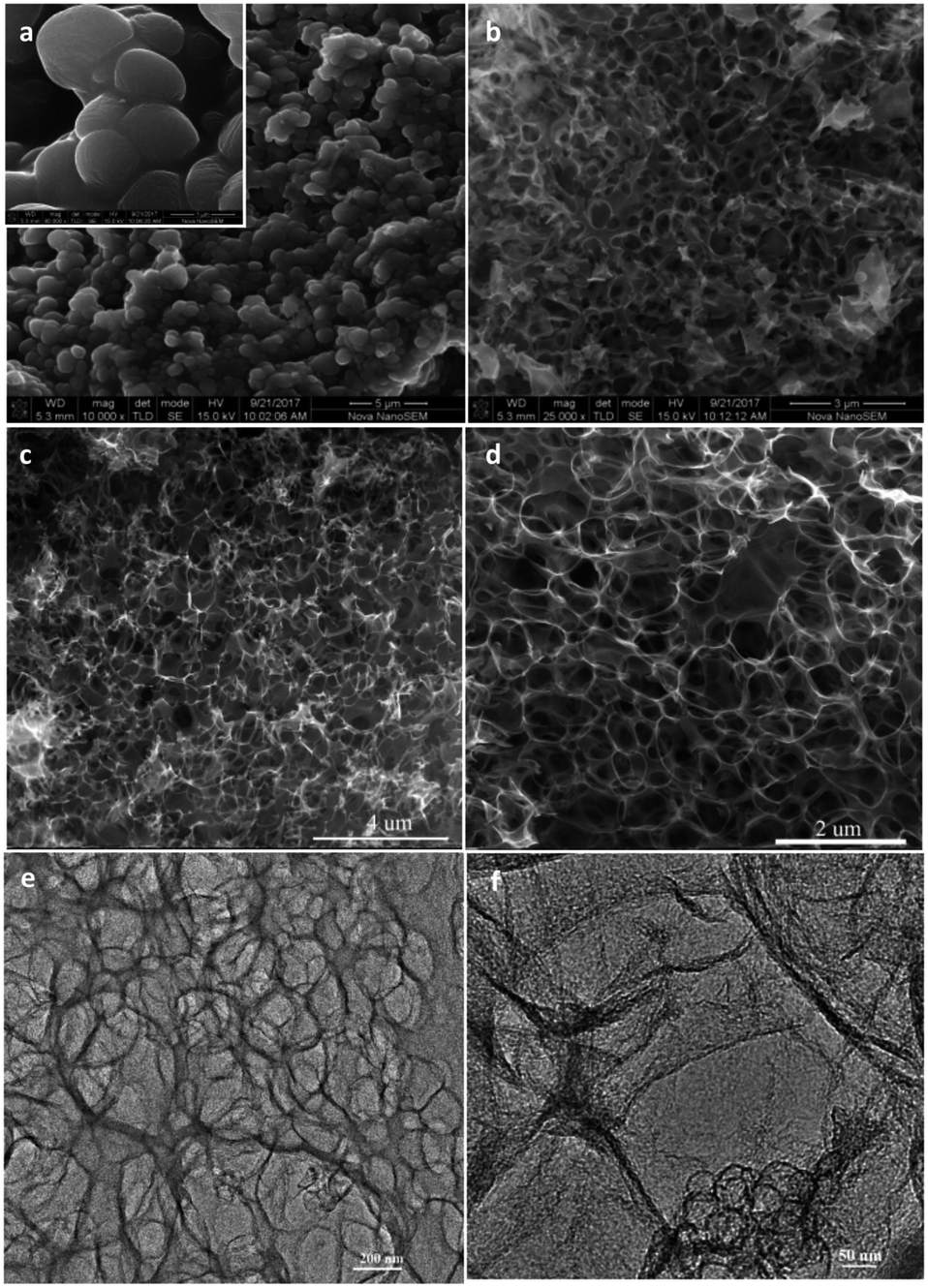 | ||
| Fig. 1 SEM images of C@Na2CO3 (a) and MPC-1 (b), (c, d) SEM images and (e, f) TEM images of HPC-1. | ||
For comparison, the weight ratio between Na2CO3 and starch is tailored, and HPC-2 (Fig. 2a and b) and HPC-3 (Fig. 2c and d) are also obtained. When the amount of Na2CO3 is increased, it can be observed that some interconnecting well-ordered macroporous network structures are destroyed (Fig. 2a and b). On the contrary, the unhomogeneous macroporous network structure is gained and the carbon walls become thicker with the reducing of the amount of Na2CO3 (Fig. 2c and d), and a thick bulk structure is obtained under the same conditions without Na2CO3 particles (the inset of Fig. 2d). It also means that Na2CO3 particles play an important template role in the formation of the interconnected macroporous network structure and the proper amount probably could produce the promised structure with high performance. From the general morphologies, we preliminarily predict that HPC-1 maybe have better electrochemical performances.
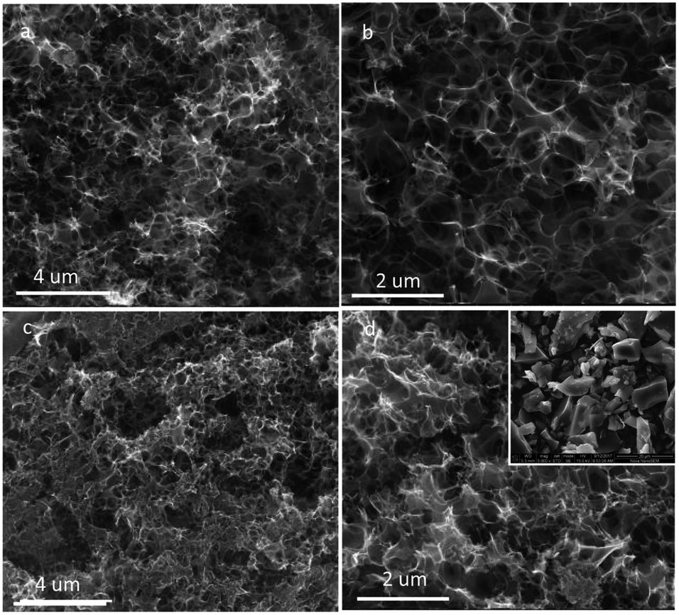 | ||
| Fig. 2 SEM images of HPC-2 (a, b), HPC-3 (c, d) and obtained carbon by direct pyrolysis of starch without Na2CO3 (the inset of d). | ||
To further characterize the pores of the HPC-1, N2 adsorption–desorption isothermal analysis was performed, as shown in Fig. 3. The steep increase at low relative pressure (P/P0) indicates the formation of micropores in large quantities,29 and there exists a hysteresis loop after P/P0 = 0.4, illustrating the presence of mesopores (Fig. 3a). There is no adsorption plateau near P/P0 = 1.0, suggesting the existence of macropores23 (Fig. 3a), which is agreement with the SEM and TEM images. The BET surface area and micropore volume of HPC-1 (1171 m2 g−1 and 0.3533 cm3 g−1) are much higher than those of MPC-1 (89.51 m2 g−1 and 0.0422 cm3 g−1), suggesting that much more micropores and mesopores are produced in HPC-1 by KOH activation (Fig. 3a and the inset).26–28 It can also be clearly seen that HPC-1 contains abundant micropores, mesopores and macropores from Fig. 3b. The results indicates that the hierarchical construction assembled from interconnected micro-, meso-, and macropores with high specific surface area can be easily obtained by a simple rapid pyrolysis of starch in the presence of Na2CO3 template followed by KOH activation, which will facilitate charge storage and fast ion transport, and thus could improve the electrochemical performance.30
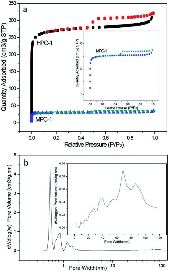 | ||
| Fig. 3 N2 absorption/desorption isotherm of MPC-1 and HPC-1 (a) and pore size distribution of HPC-1 (b). | ||
To evaluate the electrochemical performance of the HPCs, CV, EIS and GCD measurement were carried out in a 6 M KOH aqueous electrolyte in a three-electrode configuration. Fig. 4a represents the CV plots of HPC-1, HPC-2 and HPC-3 at a scan rate of 50 mV s−1. The CV profiles of all samples exhibit a quasi-rectangular shape, demonstrating good capacitive behavior. The current density response for the HPC-1 is much larger than that of HPC-2 and HPC-3 at the same scan rate, indicating that HPC-1 has a higher Csp, which is associated with the suppose from the SEM results. Fig. 4b displays the CV plots of HPC-1 at scan rates between 5 mV s−1 and 50 mV s−1. The obvious increase of the current with the scan rate reveals the desirable rate capability of HPC-1 electrode. In addition, the quasi-rectangular shape can be still maintained with the increase of potential scan rate, showing that HPC-1 possess excellent capacitive behavior at high scan rates, which may be attributed to the optimum hierarchical pore structure that combines macropores, mesopores and micropores as well as excellent electrical conductivity.31
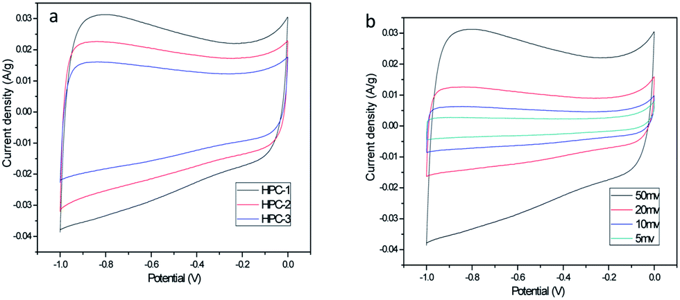 | ||
| Fig. 4 (a) CV curves of HPC-1, HPC-2 and HPC-3 at a scan rate of 50 mV s−1 (b) CV curves of HPC-1 at various scan rates. | ||
The performance of the electrode materials are further analyzed by GCD method. Fig. 5a displays the charge–discharge curves of the obtained three HPCs at a current density of 0.5 A g−1, and Fig. 5b shows the charge–discharge curves of HPC-1 at different current density. The perfect isosceles triangular GCD curves of all the samples indicate a reversible, ideal electric double layer capacitor (EDLC) behavior, and high charge–discharge efficiency. The discharging time of HPC-1 is obviously longer than that of the other HPCs, revealing that HPC-1 offers much larger charge storage ability, which is also consistent with the CV test results. The Csp values are calculated using GCD analysis data, and the values of HPC-1, HPC-2 and HPC-3 are 249.2 F g−1, 213.8 F g−1 and 159.3 F g−1 at 0.5 A g−1, respectively. HPC-1 presents the highest Csp, possibly due to its uniform and well-ordered macroporous network structure at the optimized weight ratio between starch and Na2CO3, which is also in agreement with the SEM images and CV results. The synergistic effect of macropores, mesopores and micropores can minimize the interfacial resistance of the charge transfer process and provide better access for the electrolyte into the entire structure. The Csp values of HPCs exhibit an overall gradual decrease with the increase of current density (Fig. 5c), which results from the partial active material having insufficient time available for ion diffusion and adsorption at high current density.32 The calculated Csp values of HPC-1 were 278.4, 249.2, 236.3, 230.3, 226.6, 227, 228.9 F g−1 at a discharge current density of 0.2, 0.5, 1, 2, 5, 10 and 15 A g−1, respectively. Moreover, even at a high current rate of 18 A g−1, the HPC-1 can still deliver a high capacitance of 226.1 F g−1, which is much higher than that of HPC-2 (192 F g−1), HPC-3 (151.9 F g−1) and many previously reported carbon materials,13,23,24,33–36 such as hierarchical porous carbon foams (182 F g−1 at 10 A g−1)23 and 3D hierarchial graphene-CNT composites (167 F g−1 at 10 A g−1).33 The capacitance retention is 90.7%, 89.8% and 95.4% of the initial capacitance at 0.5 A g−1 for HPC-1, HPC-2 and HPC-3, respectively, indicating the excellent rate capability and high capacitance retention of HPC-1 during fast charging/discharging, which are critical for high-performance supercapacitors. It may be owing to the good conductivity and well developed hierarchical porosity, in which the interconnected macropores serve as electrolyte reservoirs to reduce the diffusion distances of charges; while the small mesopores allow the fast ions transfer at high current density.37 Cyclic stability of the electrode is one of the most important factors in determining the supercapacitors for practical applications. Fig. 5d shows the retention of Csp over 5000 cycles of the prepared HPCs at a current density of 5 A g−1. It can be seen that the as-prepared electrode materials exhibit excellent cycle stability: capacity retention can be still maintained at 94.9%, 90.8% and 92% for HPC-1, HPC-2 and HPC-3, respectively. The excellent cycle stability should be attributed to the unique structural feature of the as-prepared HPCs.
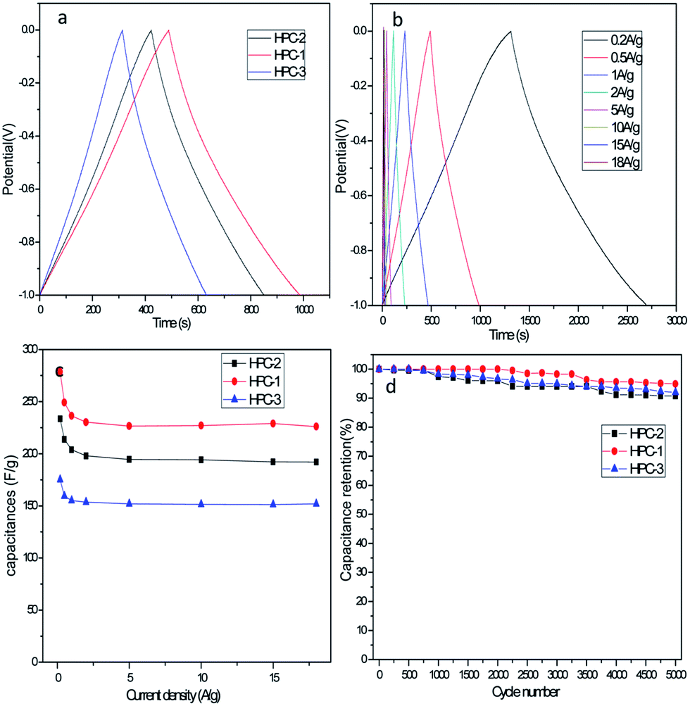 | ||
| Fig. 5 (a) Charge–discharge curves of HPC-1, HPC-2 and HPC-3 electrode at the current density of 0.5 A g−1, (b) charge–discharge curves of HPC-1 at various current densities. (c) The Csp values of the HPCs as a function of current density, (d) the cycling performance of the HPCs at a constant current density of 5 A g−1. | ||
EIS analysis is a tool to examine the electrical conductivity and ion transfer of the electrode materials. Fig. 6 shows Nyquist plots of the obtained HPCs with a frequency range from 0.01 to 100 kHz in 6 M KOH solution. All the impedance spectra of the samples are almost similar, which contain a high-frequency semicircle and a low-frequency sloping straight line. At high frequency, the equivalent series resistance (Rs) of the electrode can be obtained from the intercept at real axis and the charge transfer resistance (Rct) can be obtained from the radius of the semicircle impedance loop. It is accepted that the semicircle reflects the electrochemical reaction impedance of the electrode and a bigger semicircle means a large charge-transfer resistance.37 It can be calculated that the HPCs have the low Rs values (0.71, 0.60 and 0.75 Ω for HPC-1,2,3, respectively), and HPC-1 has the smaller Rct value (0.09 Ω) than that for HPC-2 (0.27 Ω) and HPC-3 (0.45 Ω), which suggest that the HPC-1 has a low charge transfer resistance at high frequency ranges. The straight line indicates the diffusion of the electroactive species and a higher slope signifies lower diffusion rate. It is obvious that all the low-frequency lines are closer to the vertical, which also indicate their low diffusion resistance and good electrochemical capacitive properties.38 The EIS results further demonstrate that the HPC-1 has the good electrical conductivity and the ability of rapid electron and ion transport, which is consistent with the CV and GCD results.
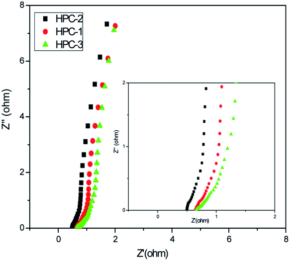 | ||
| Fig. 6 Nyquist plots of HPCs electrode (the inset is the magnified plots). | ||
From the practical perspective, we further investigated the electrochemical performance of HPC-1 in a symmetrical two-electrode system in 6 M KOH aqueous electrolyte. EIS measurement reveals that the Rs values and the Rct values are 0.90 and 0.77 Ω, respectively, and slope line is closer to the vertical (Fig. 7a), indicate the low charge transfer resistance and low diffusion resistance. As expected, the quasi-rectangular CV curves at various scan rates ranging from 5 to 50 mV s−1 (Fig. 7b) and the isosceles triangular GCD curves at various current densities (Fig. 7c) reflect the perfect double-layer capacitive characteristics of the symmetric supercapacitor. The Csp values of HPC-1 in the two-electrode system (237.5 F g−1 at 0.1 A g−1, 208.8 F g−1 at 10 A g−1) are still impressive and comparable to many other reported high-performance carbon materials.13,21 Furthermore, HPC-1 delivers an energy density of 33 W h kg−1 at a power density of 100 W kg−1 and still remains a relatively high energy density of 29 W h kg−1 when the power density increases to 10 kW kg−1, which is much higher than that of the reportes.23,39,40 As illustrated in Fig. 7d, 80.2% retention of the initial Csp after 5000 cycles at 5 A g−1 suggests that HPC-1 is a promising candidate for long-term energy storage devices.
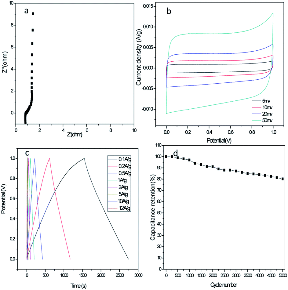 | ||
| Fig. 7 (a) Nyquist plots (b) CV curves (c) charge–discharge curves at various current densities (d) the cycling performance of HPC-1 at a constant current density of 5 A g−1 in a two-electrode system. | ||
Conclusions
In summary, a facile and green synthesis route has been developed for the successful fabrication of hierarchical porous carbon materials with the interconnected macropores, mesopores and micropores from starch. HPC-1 demonstrates high Csp of 226.1 F g−1 at 18 A g−1, good rate performance (capacitance retention is 90.7% of the initial capacitance at 0.5 A g−1) and long cyclic stability (94.9% retention after continuous 5000 cycles at a current density of 5 A g−1) in a three-electrode system, and delivers a high energy density of 33 W h kg−1 at a power density of 100 W kg−1 in the symmetric supercapacitor. Such excellent electrochemical performance could be contributed to the combination of various pores: well-order macropores act as the ion reservoir and shorten the ion diffusion distance; mesopores allow electrolyte ions to transfer rapidly; micropores could significantly increase the specific surface area of carbon materials and thus enhance the electrical double layer capacitance. The excellent electrochemical properties suggest that the as-synthesized hierarchical porous carbons could be a good candidate for supercapacitor electrode materials, and we believe that they would have great potential for other functional applications, such as catalyst support, gas storage and other batteries. It is to be noted that we emphasized the employing of water-soluble and renewable Na2CO3 as templates and provided a simple and effective synthesis method for the synthesis of hierarchical porous carbon in this paper, and the low-cost starch also can be replaced by other carbon precursors. The facile synthesis method would open up an effective route for the synthesis of many other hierarchical porous carbon-based materials in a large scale.Conflicts of interest
There are no conflicts to declare.Acknowledgements
This work was supported by National Natural Science Foundation of China (No. 51102180), and supported by the Program for innovative Research Team in University of Tianjin (No. TD12-5038).Notes and references
- Z. Yang, J. Zhang, M. C. Kintner-Meyer, X. Lu, D. Choi, J. P. Lemmon and J. Liu, Chem. Rev., 2011, 111, 3577–3613 CrossRef CAS PubMed.
- P. Simon and Y. Gogotsi, Nat. Mater., 2008, 7, 845–854 CrossRef CAS PubMed.
- P. Yang, Y. Ding, Z. Lin, Z. Chen, Y. Li, P. Qiang, M. Ebrahimi, W. Mai, C. P. Wong and Z. L. Wang, Nano Lett., 2014, 14, 731–736 CrossRef CAS PubMed.
- M. F. EI-Kady and R. B. Kaner, Nat. Commun., 2013, 4, 1475–1483 CrossRef PubMed.
- W. Fan, C. Zhang, W. W. Tjiu, K. P. Pramoda, C. He and T. Liu, ACS Appl. Mater. Interfaces, 2013, 5, 3382–3391 CAS.
- G. Sun, X. Zhang, R. Lin, J. Yang, H. Zhang and P. Chen, Angew. Chem., Int. Ed., 2015, 127, 4734–4739 CrossRef.
- S. Faraji and F. N. Ani, Renewable Sustainable Energy Rev., 2015, 42, 823–834 CrossRef CAS.
- L. L. Zhang and X. S. Zhao, Chem. Soc. Rev., 2009, 38, 2520–2531 RSC.
- D. S. Yu and L. M. Dai, J. Phys. Chem. Lett., 2010, 1, 467–470 CrossRef CAS.
- Y. X. Xu, G. Q. Shi and X. F. Duan, Acc. Chem. Res., 2015, 48, 1666–1675 CrossRef CAS PubMed.
- Z. J. Fan, Q. K. Zhao, T. Y. Li, J. Yan, Y. M. Ren, J. Feng and T. Wei, Carbon, 2012, 50, 1699–1703 CrossRef CAS.
- B. J. Jiang, C. G. Tian, L. Wang, L. Sun, C. Chen, X. Z. Nong, Y. G. Qiao and H. G. Fu, Appl. Surf. Sci., 2012, 258, 3438–3443 CrossRef CAS.
- Z. J. Li, W. Lv, C. Zhang, B. H. Li, F. Y. Kang and Q. H. Yang, Carbon, 2015, 92, 11–14 CrossRef CAS.
- W. Xing, C. C. Huang, S. P. Zhuo, X. Yuan, G. Q. Wang, D. Hulicova-Hurcakova, Z. F. Yan and G. Q. Lu, Carbon, 2009, 47, 1715–1722 CrossRef CAS.
- K. A. Cychosz, R. Guillet-Nicolas, J. Garcia-Martinez and M. Thommes, Chem. Soc. Rev., 2017, 46, 389–414 RSC.
- F. Xu, R. J. Cai, Q. C. Zeng, C. Zou, D. C. Wu, F. Li, X. Lu, Y. R. Liang and R. W. Fu, J. Mater. Chem., 2011, 21, 1970–1976 RSC.
- D. W. Wang, F. Li, M. Liu, G. Q. Lu and H. M. Cheng, Angew. Chem., Int. Ed., 2008, 47, 373–376 CrossRef CAS PubMed.
- Y. Han, X. T. Dong, C. Zhang and S. X. Liu, J. Power Sources, 2012, 211, 92–96 CrossRef CAS.
- S. Dutta, A. Bhaumik and K. C.-W. Wu, Energy Environ. Sci., 2014, 7, 3574–3592 CAS.
- J. Deng, M. M. Li and Y. Wang, Green Chem., 2016, 18, 4824–4854 RSC.
- A. Bello, N. Manyala, F. Barzegar, A. A. khaleed, D. Y. Momodu and J. K. Dangbegnon, RSC Adv., 2016, 6, 1800–1809 RSC.
- Y. T. Luan, L. Wang, S. Guo, B. J. Jiang, D. D. Zhao, H. J. Yan, C. G. Tian and H. G. Fu, RSC Adv., 2015, 5, 42430–42437 RSC.
- P. Hao, Z. H. Zhao, J. Tian, H. D. Li, Y. H. Sang, G. W. Yu, H. Q. Cai, H. Liu, C. P. Wong and A. Umar, Nanoscale, 2014, 6, 12120–12129 RSC.
- Y. K. Lv, L. H. Gan, M. X. Liu, W. Xiong, Z. J. Xu, D. Z. Zhu and D. S. Wright, J. Power Sources, 2012, 209, 152–157 CrossRef CAS.
- Y. J. Cai, Y. Luo, X. Zhao, Y. Xiao, Y. R. Liang, H. Hu, Y. L. Liu and M. T. Zheng, J. Power Sources, 2017, 353, 260–269 CrossRef CAS.
- Y. W. Zhu, S. Murali, M. D. Stoller, K. J. Ganesh, W. W. Cai, P. J. Ferreira, A. Pirkle, R. M. Wallace, K. A. Cychosz, M. Thommes, D. Su, E. A. Stach and R. S. Ruoff, Science, 2011, 332, 1537–1541 CrossRef CAS PubMed.
- J. Liu, X. Y. Wang, J. Gao, Y. W. Zhang, Q. Lu and M. Liu, Electrochim. Acta, 2016, 211, 183–192 CrossRef CAS.
- Z. Li, K. K. Guo and X. L. Chen, RSC Adv., 2017, 7, 30521–30532 RSC.
- W. Lin, B. Xu and L. Liu, New J. Chem., 2014, 38, 5509–5514 RSC.
- Q. H. Liang, L. Ye, Z. H. Huang, Q. Xu, Y. Bai, F. Y. Kang and Q. H. Yang, Nanoscale, 2014, 6, 13831–13837 RSC.
- W. Xing, C. C. Huang, S. P. Zhuo, X. Yuan, G. Q. Wang, D. Hulicova-Jurcakova, Z. F. Yan and G. Q. Lu, Carbon, 2009, 47, 1715–1722 CrossRef CAS.
- D. Ghosh, S. Giri and C. K. Das, ACS Sustainable Chem. Eng., 2013, 1, 1135–1142 CrossRef CAS.
- Y. Wang, Y. Wu, Y. Huang, F. Zhang, X. Yang, Y. Ma and Y. Chen, J. Phys. Chem. C, 2011, 115, 23192–23197 CAS.
- M. Klose, R. Reinhold, K. Pinkert, M. Uhlemann, F. Wolke, J. Balach, T. Jaumann, U. Stoeck, J. Echert and L. Giebeler, Carbon, 2016, 106, 306–313 CrossRef CAS.
- G. F. Ma, F. T. Ran, H. Peng, K. J. Sun, Z. G. Zhang, Q. Yang and Z. Q. Lei, RSC Adv., 2015, 5, 83129–83138 RSC.
- Y. W. Qiang, J. G. Jiang, Y. C. Xiong, H. Chen, J. Y. Chen, S. Y. Guan and J. D. Chen, RSC Adv., 2016, 6, 9772–9778 RSC.
- Y. Li, Q. Wang, P. P. Liu, X. H. Yang, G. X. Du and Y. Liu, Ceram. Int., 2015, 41, 4248–4253 CrossRef CAS.
- H. J. Yan, J. W. Bai, J. Wang, X. Y. Zhang, B. Wang, Q. Liu and L. H. Liu, CrystEngComm, 2013, 15, 10007–10015 RSC.
- L. Y. Pang, B. Zou, X. Han, L. Y. Cao, W. Wang and Y. P. Guo, Mater. Lett., 2016, 184, 88–91 CrossRef CAS.
- H. B. Feng, H. Hu, H. W. Dong, Y. Xiao, Y. J. Cai, B. F. Lei, Y. L. Liu and M. T. Zheng, J. Power Sources, 2016, 302, 164–173 CrossRef CAS.
| This journal is © The Royal Society of Chemistry 2017 |