 Open Access Article
Creative Commons Attribution 3.0 Unported Licence
Characterization of the crystalline regions of cured urea formaldehyde resin
Ming Liu ab,
Rooban Venkatesh K. G. Thirumalaic,
Yiqiang Wub and
Hui Wan*a
aDepartment of Sustainable Bioproducts, College of Forest Resources, Mississippi State University, Mississippi State, Mississippi 39762, USA. E-mail: hw2@msstate.edu
bCollege of Materials Science and Engineering, Central South University of Forestry and Technology, Changsha, 410004, China
cInstitute for Imaging & Analytical Technologies, Mississippi State University, Mississippi State, Mississippi 39762, USA
First published on 25th October 2017
Abstract
Urea formaldehyde (UF) resins are widely used thermosetting polymers in adhesives, finishes, molded objects, etc. The existence of crystalline regions has been detected in UF resins. These crystalline regions are believed to be beneficial for the hydrolytic stability or water resistance and advanced mechanical properties of the resin. In this study, characterization was conducted on crystalline regions of a cured UF resin with a formaldehyde to urea (F/U) molar ratio of 1.2. A slow scanned X-ray diffraction (XRD) pattern was obtained to estimate the crystalline percentage, grain sizes, and interplanar spacing (d-spacing) of the resin crystalline structures. The results showed that the crystalline regions accounted for nearly 14.48% of the resin. From the XRD pattern, the estimated grain size of 4.1 nm was accounted for the peak (two theta degrees, 2θ) of 21.55°, 4.1 nm for 24.35°, 4.2 nm for 31.18°, and 4.8 nm for 40.43°, respectively. Furthermore, a selected area electron diffraction (SAD) pattern of the resin was obtained to confirm the results. The calculated d-spacing values were 2.2242 Å for the peak (2θ) of 21.55°, 1.2833 Å for 24.35°, and 1.0978 Å for 31.18°, respectively. The obtained SAD pattern matched the corresponding XRD pattern of a UF resin. This work provides information for studying the mechanism of formation and the application of crystalline regions of UF resins.
1. Introduction
Urea formaldehyde (UF) resins are thermosetting polymers. They are composed of non-reacted monomers and branched or linear oligomeric and polymeric molecules. These polymers have the advantages of high reactivity, fast curing time, relatively low price, relatively strong bonding strength, and clear color, which make them one of the major adhesives for the wood industry. They are widely used in particleboard, medium density fiber board, and interior plywood manufacturing. These so-called aminoplastic resins, even though they are a chemical product from the reaction of two simple monomers: urea and formaldehyde, have a countless variety of condensed structures under various reaction conditions.1 In spite of their advantages, UF resins are limited in interior utilization due to their low water or moisture resistance. Also, the resin utilization may cause indoor air pollution and possible health problems due to the formaldehyde emission from UF resin-bonded wood products.2 The source of formaldehyde from UF resin-bonded wood products is believed mainly to be from un-reacted formaldehyde and the reversibility of aminomethylene links in the cured resin network. These reversible links are also the major reason for the low water resistance of UF resins.3The modification of UF resin for lowering formaldehyde emission and enhancing water resistance has attracted tremendous attention. The modification of the resin begins with its selective synthesis parameters. Among them, the most significant factor in resin synthesis is the formaldehyde to urea (F/U) molar ratio. This ratio is vital for the formaldehyde content, resin viscosity, curing time, shelf time, crosslinking degree, and relative molecular weight distribution. To date, the widespread method for reducing the formaldehyde emission of a UF resin is to lower its F/U molar ratio.4 The mechanical and chemical properties of low and high F/U molar ratio UF resins are different. For example, a dynamic mechanical analysis illustrated that the rigidity of a UF resin decreased as the F/U molar ratio decreased, but the gel time increased, which partially explained the poor adhesion performance of the low F/U molar ratio UF resin.5 In addition, catalysts in UF resin synthesis play an important role in the formation of functional groups and ratio of condensed structures, which influence the resin polymerization.6 Interestingly, under the low F/U molar ratios, crystalline structures have been found in the cured UF resins in situations where catalyst were and were not used.7 Nowadays, an increasing number of research papers have reported crystalline regions of UF resins.
The shape and distribution of the crystalline structures on the resin surface have been explored using an atomic force microscopy. The related results showed that the crystalline regions have increased the UF resin's hydrolytic degradation behavior.8 The relationship between F/U molar ratios and hydrolytic stabilities of UF resins has been further explored. Some results showed that the lower F/U molar ratio was found the UF resin has, a higher ratio of crystalline regions occurs; thus, a higher resistance to hydrolysis.9 In addition, crystalline and domain sizes in various F/U molar ratio UF resins have also been calculated from X-ray diffraction (XRD) patterns and X-ray scattering techniques. The crystalline percentages in cure UF resins was increased from 26% to 48% with the decrease of F/U molar ratio from 1.6 to 1.0. The domain sizes also increased from nearly 1 nm to 5 nm with this change.10
To confirm the existence of crystalline regions in a UF resin cured in contact with wood, an electron diffraction (ED) pattern was obtained from the resin particles. This ED pattern contained a big white halo in the middle and overlapped with thick and blurry diffracted electron rings. It has been concluded that the electron rings in their ED pattern confirmed the crystalline regions of the UF resin.11 Liquid UF resins have also been observed with a transmission electron microscope (TEM) to further explore the mechanism and the development of crystalline regions in UF resins. Images were obtained from the TEM. The results might not be appropriate to determine the crystalline structures of the resin sample.12 The clearest image here showed a scale bar of 500 nm, which is impossible to observe the atom level distances between the planes of a crystal. To confirm the crystalline structure of an analyte, the most reliable way is to obtain its electron diffraction pattern.
The existence of crystalline regions in a UF resin could act as reinforced structure for the resin.13 The right type of crystal formations in the resin could reinforce the performance of the resin substrate in different aspects, i.e. compact strength. The dispersion of crystal domains in the resin could also influence other functional modifications using the nanoparticles concept.14 UF resins were used as the shell of capsules for self-healing polymers. Hence, the crystalline UF resin shell might be used as functional fillers for self-healing polymers.15 However, the mechanism for the formation of the crystalline regions in UF resins is still unknown, including their chemical components or molecular structures. In addition, the crystalline region characterization for UF resins lacks information of grain size, d-spacing, etc. The X-ray diffraction (XRD) pattern is obtained from the diffracted X-ray beams when the incident beams pass through crystals. Meanwhile, a selected area diffraction (SAD) pattern is obtained from the diffracted electrons in the same manner of the XRD pattern. The XRD pattern of a material is the integration of the radius across the SAD pattern of it. This means that the indexed plane of a peak in a XRD pattern should match the indexed plane of a ring in its SAD pattern.16 There was, however, no reported SAD pattern that matched the related XRD pattern of UF resin's crystalline regions. In this present work, a low F/U molar ratio (1.2) UF resin was prepared for the resin crystalline region characterization. A slow scanned XRD pattern of the UF resin was obtained and used for calculations of crystalline percentage, grain size, and d-spacing values of crystalline structures. The corresponding SAD pattern was obtained to confirm its crystalline features. To the best of our knowledge, this is the first time that the matched XRD and SAD pattern of UF resin crystalline regions were obtained.
2. Materials and methods
2.1 Materials
Paraformaldehyde (HO(CH2O)nH), in its crystalline form and reagent grade, was purchased from Sigma Aldrich, USA. Urea (NH2CONH2), in its crystalline form, 98% pure, was purchased from Alfa Aesar, USA. Sodium hydroxide beads (NaOH), ammonium sulfate ((NH4)2SO4), ammonium chloride (NH4Cl), 1 N sulfuric acid (H2SO4), and 1 N hydrochloric acid (HCl), certified ACS plus, were purchased from Fisher Scientific, USA. All chemicals were used as received without further purification except for dilution to achieve different desired concentrations.2.2 Experimental methods
3. Results and discussion
3.1 UF resin chemical composition
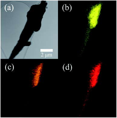
The element composition of the UF resin was detected using an EDS. The typical TEM image and the elements mapping of UF resin particles are shown in Fig. 1. UF resins were prepared from urea and formaldehyde, which only contained the elements of carbon (C), nitrogen (N), and oxygen (O). Hence, the major elements of the resin were C (49.8%), N (32.1%), and O (18.0%). The existence of trace elements was introduced by hardeners or other impurities. Because of this, it is assumed that the possible crystalline structures in the UF resin could only be formed through these three major elements.The ATR-FTIR spectra of the cured UF resins are shown in Fig. 2. The broad band at 3300–3350 cm−1 was assigned to the N–H stretching of secondary amides. Urea contains primary amines, which indicates that the urea might be fully reacted during the resin preparation and curing process. The peaks at 1632 cm−1 and 1550 cm−1 were attributed to the stretching of carbonyl group (C![[double bond, length as m-dash]](https://www.rsc.org/images/entities/char_e001.gif) O) and C–N stretching of secondary amines, respectively. The peak at 1378 cm−1 was assigned to –CH2OH, this illustrates the typical reaction between urea and formaldehyde.11 The peak of 1238 cm−1 was attributed to the stretching of C–N and N–H of tertiary amines. The other observed peaks of 1130 cm−1 and 1035 cm−1 were assigned to C–O aliphatic ether and methylene bridge (–NCH2N–), respectively.17 The occurrences of the bands confirmed the polymerization of UF resins during a curing process. The obtained results were similar to the other FTIR spectra of cured UF resins with the addition of hardeners.11 These results indicate that the acid type for pH value control and hardener type for UF resin curing had no significant influence on resin chemical compositions.
O) and C–N stretching of secondary amines, respectively. The peak at 1378 cm−1 was assigned to –CH2OH, this illustrates the typical reaction between urea and formaldehyde.11 The peak of 1238 cm−1 was attributed to the stretching of C–N and N–H of tertiary amines. The other observed peaks of 1130 cm−1 and 1035 cm−1 were assigned to C–O aliphatic ether and methylene bridge (–NCH2N–), respectively.17 The occurrences of the bands confirmed the polymerization of UF resins during a curing process. The obtained results were similar to the other FTIR spectra of cured UF resins with the addition of hardeners.11 These results indicate that the acid type for pH value control and hardener type for UF resin curing had no significant influence on resin chemical compositions.
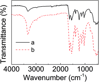 | ||
| Fig. 2 ATR-FTIR spectra of cured UF resin powders: (a) type “a” resin powder; (b) type “b” resin powder. | ||
3.2 XRD pattern of cured UF resin
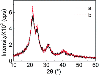
The normal XRD patterns of two UF resins are shown in Fig. 3. The occurrences of the peaks confirmed the existence of crystalline regions in cured UF resins. The 2θ degrees for the peaks were 21.55°, 24.35°, 31.18°, and 40.43°, respectively. Once again, there was no significant difference between these two resin types, concerning XRD spectra. The results indicate that acid and hardener types for pH value control during resin preparation and resin curing, respectively, did not influence the formation and the development of the crystalline structures in cured UF resins.12 The higher intensity in type “b” resin at 2θ degrees of 21.55° and 24.35° might be attributed to a higher population of the related crystalline regions. This indicates that the types of hardener and acid could control the percentage of crystalline regions in cured UF resins even at the same F/U molar ratio.3.3 Slow scan XRD pattern
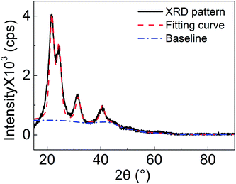
A better signal to noise ratio of XRD pattern was obtained from a slow scan experiment; that is, the peaks of the XRD pattern obtain more counts and grow out far more from the background. In addition, minor components in the resin were detected. To do quantitative analysis of the cured UF resin particles, a zero-background sample holder was used, and the slow scanned XRD pattern is shown in Fig. 4. Data analysis was conducted using the MDI jade 2010 software. After the automatic simulation and curve fitting process were completed in the software, the percentage of crystalline in the resin particles, grain sizes, and d-spacing values of the related crystalline were obtained (Table 1). The crystalline percentage was 14.48% in this analysis. Considering the curve fitting process, this value was the maximum crystalline percentage in the UF resin. The actual percentage was not greater than this value since the background broadening is nearly impossible to eliminate. However, a crystalline percentage of nearly 45% was reported with the same 1.2 F/U molar ratio UF resin.10 The difference between the XRD patterns in this study and the reported data is not significantly different. It indicates that the calculated crystalline percentages should be close to each other. Hence, this discrepancy is mainly attributed to the used computational program and simulation process. The reported high crystalline percentage value was obtained from the method published in 1971, which is based on a program in 1964.18 It might not be appropriate to compare these percentage values under the circumstance. In addition, the d-spacing values for the corresponding peaks were obtained, 4.12 Å for 2θ degree of 21.55°, 3.65 Å for 24.35°, 2.86 Å for 31.18°, and 2.23 Å for 40.43°, respectively. The grain sizes for all the crystalline regions were close to each other, and the average size was approximately 4.1 nm. For further confirmation of d-spacing values, the related SAD patterns are needed.| Angle (°) | d-Spacing (Å) | Grain size (nm) |
|---|---|---|
| 21.55 | 4.12 | 4.1 |
| 24.35 | 3.65 | 4.1 |
| 31.18 | 2.86 | 4.2 |
| 40.43 | 2.23 | 4.3 |
3.4 TEM images and SAD pattern of the cured UF resin
The TEM images and SAD patterns of UF resin particles are shown in Fig. 5. The observed UF resin particles were randomly distributed with irregular shapes. Fig. 5(a) and (b) were examples of typical UF resin particles. The observed morphology and shape were not like the UF resin particles in a previous study.11 This was attributed to the sample preparation process. In the present work, bulk UF resins were ground to particles. While in the previous study, the resin particles were observed on wood substrate. Fig. 5(c) shows the image of the area of the UF resin particle that was used for the SAD pattern. The location is also described in Fig. 5(b), within the circled area. Fig. 5(d) is the SAD pattern of the resin particle in Fig. 5(c). In this SAD pattern, it is obvious that crystalline regions existed in the cured UF resin. However, the crystalline percentage was quite low, as indicated in the slow scanned XRD pattern, as only 14.48%. Due to the dominated area of amorphous regions, the diffracted electron rings were blurry. This was the most common SAD pattern for the resin particles. The obtained SAD pattern in Fig. 5(d) shows three diffracted electron rings, which matches their XRD pattern, while in other reported data, the SAD pattern didn't not match their XRD pattern. The XRD pattern only presented one broad peak and no clear diffracted electron rings was shown in the related ED pattern.11 In this SAD pattern, each ring had a certain thickness. This might be induced by the electron diffraction of multiple overlapped crystalline regions. To our surprise, for the observed area of UF resin particles in Fig. 5(e), a much clearer SAD pattern was obtained, as showed in Fig. 5(f).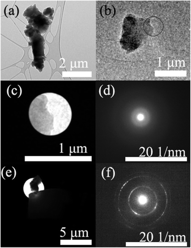 | ||
| Fig. 5 TEM images and SAD patterns of UF resin particles: (a) and (b) are UF resin particles; (d) is the SAD pattern of (c); and (f) is the SAD pattern of (e). | ||
Once again, there are three clear rings in the image. To the best of our knowledge, this is the first clear SAD pattern of UF resin crystalline regions. The subsequent d-spacing values calculation was conducted using the Image J software. The calculated data are shown in Table 2. From the clear SAD pattern, the d-spacing values were calculated as 2.2242 Å, 1.2833 Å, and 1.0978 Å, respectively. These d-spacing values were corresponded to the 2θ degrees of 21.55°, 24.35°, and 31.18°, respectively. The obtained data are different from the data in the simulated slow scanned XRD pattern. This might be attributed to the lack of data in the MDI Jade database for these specific crystalline regions. Further research is needed to verify this.
| Rings (numbered from inside) | 2θ degree | d-Spacing (Å) |
|---|---|---|
| 1 | 21.55° | 2.2242 |
| 2 | 24.35° | 1.2833 |
| 3 | 31.18° | 1.0978 |
4. Conclusions
UF resin applications are ubiquitous in adhesives and other polymer based products. The existence of crystalline regions in low F/U molar ratio UF resins has attracted a new desire to understand this thermosetting polymer. In this work, the crystalline regions of a pure UF resin particles with the F/U molar ratio of 1.2 have been characterized. The obtained SAD pattern matched the resin's XRD pattern, which confirmed the existence of crystalline regions in the resin. Furthermore, an estimated crystalline percentage of 14.48% was obtained based on the simulation of a slow scanned XRD pattern. A clear SAD pattern of the resin was obtained. The calculated d-spacing values were 2.2242 Å for the peak (2θ) of 21.55°, 1.2833 Å for 24.35°, and 1.0978 Å for 31.18°, respectively. These are the first obtained d-spacing values on UF resin crystalline regions. The knowledge presented in this work provides information for the resin's practical application and future theoretical studies.Conflicts of interest
There are no conflicts to declare.Acknowledgements
The authors are grateful to Dr Gerald T. Baker for the instructions and the support from the Institute for Imaging & Analytical Technologies, Mississippi State University. The authors are also grateful for the financial support of the US Department of Agriculture, National Institute of Food and Agriculture, McIntire-Stennis Cooperative Forestry Research Program. This manuscript is published as Journal Article SB 906, Forest & Wildlife Research Center, Mississippi State University, Mississippi State, MS 39762-9820.References
- M. Dunky, Urea-formaldehyde (UF) adhesive resins for wood, Int. J. Adhes. Adhes., 1998, 18(2), 95–107 CrossRef CAS.
- S.-i. Tohmura, C.-Y. Hse and M. Higuchi, Formaldehyde emission and high-temperature stability of cured urea-formaldehyde resins, J. Wood Sci., 2000, 46(4), 303–309 CrossRef CAS.
- E. Minopoulou, E. Dessipri, G. D. Chryssikos, V. Gionis, A. Paipetis and C. Panayiotou, Use of NIR for structural characterization of urea–formaldehyde resins, Int. J. Adhes. Adhes., 2003, 23(6), 473–484 CrossRef CAS.
- M. G. Kim, Examination of selected synthesis parameters for wood adhesive-type urea–formaldehyde resins by 13C NMR spectroscopy. III, J. Appl. Polym. Sci., 2001, 80(14), 2800–2814 CrossRef CAS.
- B.-D. Park and J.-W. Kim, Dynamic mechanical analysis of urea–formaldehyde resin adhesives with different formaldehyde-to-urea molar ratios, J. Appl. Polym. Sci., 2008, 108(3), 2045–2051 CrossRef CAS.
- Q. N. Sun, C.-Y. Hse and T. F. Shupe, Effect of different catalysts on urea-formaldehyde resin synthesis, J. Appl. Polym. Sci., 2014, 131(16), 1–7 CrossRef.
- D. Levendis, A. Pizzi and E. Ferg, The correlation of strength and formaldehyde emission with the crystalline/amorphous structure of UF resins, Holzforschung, 1992, 46(3), 263–269 CrossRef CAS.
- B.-D. Park and H.-W. Jeong, Effects of acid hydrolysis on microstructure of cured urea-formaldehyde resins using atomic force microscopy, J. Appl. Polym. Sci., 2011, 122(5), 3255–3262 CrossRef CAS.
- B.-D. Park and H.-W. Jeong, Hydrolytic stability and crystallinity of cured urea–formaldehyde resin adhesives with different formaldehyde/urea mole ratios, Int. J. Adhes. Adhes., 2011, 31(6), 524–529 CrossRef CAS.
- B.-D. Park and V. Causin, Crystallinity and domain size of cured urea–formaldehyde resin adhesives with different formaldehyde/urea mole ratios, Eur. Polym. J., 2013, 49(2), 532–537 CrossRef CAS.
- A. P. Singh, V. Causin, A. Nuryawan and B. D. Park, Morphological, chemical and crystalline features of urea–formaldehyde resin cured in contact with wood, Eur. Polym. J., 2014, 56, 185–193 CrossRef CAS.
- A. Nuryawan, A. P. Singh, M. Zanetti, B. D. Park and V. Causin, Insights into the development of crystallinity in liquid urea-formaldehyde resins, Int. J. Adhes. Adhes., 2017, 72, 62–69 CrossRef CAS.
- L. Peponi, D. Puglia, L. Torre, L. Valentini and J. M. Kenny, Processing of nanostructured polymers and advanced polymeric based nanocomposites, Mater. Sci. Eng., R, 2014, 85, 1–46 CrossRef.
- S. Cheng, D. M. Smith and C. Y. Li, How Does Nanoscale Crystalline Structure Affect Ion Transport in Solid Polymer Electrolytes?, Macromolecules, 2014, 47(12), 3978–3986 CrossRef CAS.
- B. J. Blaiszik, N. R. Sottos and S. R. White, Nanocapsules for self-healing materials, Compos. Sci. Technol., 2008, 68(3–4), 978–986 CrossRef CAS.
- S. P. Usha, S. K. Mishra and B. D. Gupta, Fiber optic hydrogen sulfide gas sensors utilizing ZnO thin film/ZnO nanoparticles: a comparison of surface plasmon resonance and lossy mode resonance, Sens. Actuators, B, 2015, 218, 196–204 CrossRef CAS.
- J. Luo, J. Zhang, J. Luo, J. Li and Q. Gao, Effect of melamine allocation proportion on chemical structures and properties of melamine-urea-formaldehyde resins, BioResources, 2015, 10(2), 3265–3276 CAS.
- A. M. Hindeleh and D. J. Johnson, The resolution of multipeak data in fibre science, J. Phys. D: Appl. Phys., 1971, 4(2), 259–263 CAS.
| This journal is © The Royal Society of Chemistry 2017 |

