
 Open Access Article
 This Open Access Article is licensed under a Creative Commons Attribution-Non Commercial 3.0 Unported Licence
Nanostructured carbon–metal hybrid aerogels from bacterial cellulose†
Bernd Wicklein *a,
Judith Arranza,
Alvaro Mayoralb,
Pilar Arandaa,
Yves Huttela and
Eduardo Ruiz-Hitzkya
*a,
Judith Arranza,
Alvaro Mayoralb,
Pilar Arandaa,
Yves Huttela and
Eduardo Ruiz-Hitzkya
aInstituto de Ciencia de Materiales de Madrid, Consejo Superior de Investigaciones Científicas (CSIC), c/Sor Juana Inés de la Cruz 3, 28049 Madrid, Spain. E-mail: bernd@icmm.csic.es
bLaboratorio de Microscopías Avanzadas, Instituto de Nanociencia de Aragón, Universidad de Zaragoza, c/Mariano Esquillor, Edificio I+D, 50018, Zaragoza, Spain
First published on 30th August 2017
Abstract
Infiltration of nickel(II) hydroxide inside a bacterial cellulose gel followed by thermal treatment gives rise to highly crystalline nickel nanoparticles that remain associated with the generated carbon nanofibers. The involved mechanism, ascribed to a carbothermal reduction, takes place at an exceptionally low temperature (390 °C). This study suggests the reduction of the intermediate nickel oxide phase by carbon and CO generated during pyrolysis of bacterial cellulose, while the nascent nickel nanoparticles catalyze the formation of graphitic carbon in the form of carbon aerogels. This synthesis route also generates equivalent carbon–iron hybrids pointing to the extension of this procedure to other transition metals as well, thus producing conducting carbon foams with functional metal nanoparticles. This soft procedure opens way to new carbon–metal aerogels with potential interest in fields as diverse as catalysis, energy storage and optical devices.
Introduction
Hybrid materials composed of nanostructured carbon and metal nanoparticles (NPs) give rise to interesting scientific phenomena1 and diverse technological applications.2–5 For instance, charge transfer behavior at the carbon/metal interface results in high catalytic activity,1,6,7 while magnetic5 and optical8 properties of the metal NPs can be explored in sensing and biotechnological applications.2 Specifically, carbon–nickel nanostructured materials, often prepared by carbothermal reduction,9,10 find widespread use as energy materials and optical materials.4,6,7,11–13 Herein, specially biomass like lignocellulosics, nanocellulose, or bacterial cellulose are multifarious carbon sources due to their structural pre-organization displaying porosity, fibrous morphology, or three-dimensional (3D) networks, respectively, which can be translated into nanostructured carbon during their carbonization.14–16 Thus, careful choice of the pyrolysis conditions not only reduces the metal precursor to metal nanoparticles but concomitantly can also produce carbon nanofibers,17 carbon aerogels,18 or graphene,19 which integrate the functional metal nanoparticles.The production of carbon–metal materials usually takes place at high temperature (>600 °C) through carbothermal reduction10 but shows still a lack of understanding especially about how nascent metal NPs may influence the formation of nanostructured carbon. This aspect remains challenging,20 evident by competing views on the formation mechanism of metal–carbon hybrid materials.21,22
Bacterial cellulose is a versatile biomaterial for the formation of nanostructured hybrid materials.23 It consists of nanometer thick, highly crystalline cellulose Iα fibers produced by bacterial fermentation of glucose.24 The fibers are crosslinked forming a strong hydrogel, which allows for effective impregnation with aqueous metal salt solution.25 Subsequent reduction, hydrothermal treatment, or precipitation may render metal or metal oxide/hydroxide NPs supported on the cellulose fibers suitable for a variety of catalytic, sensing, or biomedical applications.24 On the other hand, pyrolysis of bacterial cellulose can result in graphitic carbon fiber networks17 or carbon aerogels,15 which are interesting as energy materials, absorbers, or artificial muscles.
In this paper we combined the carbon aerogel formation from bacterial cellulose with carbothermal reduction of nickel hydroxide to produce carbon–nickel hybrid foams in view of their outstanding technological importance. We precipitated nickel hydroxide nanoparticles on bacterial cellulose, which after a carbothermic reaction at a remarkably low temperature formed metallic nickel–carbon aerogels. The same methodology was also applied to ferric hydroxide for the production of iron–carbon hybrids. Potential applications of the synthesized materials can be envisaged in catalysis, electromagnetic shielding, as electrode material in Li ion batteries, and as light absorber.
Experimental section
Synthesis of carbon–nickel hybrids
Nata de coco (Fitrite Inc., Philippines) was used as source of bacterial cellulose.24 The nata de coco cubes were extensively washed with deionized water, stirred for 3 days in 0.1 M NaOH and for 2 days in deionized water and then stored refrigerated in Milli-Q water until usage. Nickel acetate (Ni(Ac)2), FeCl3 and NaOH were purchased from Sigma-Aldrich. In a typical synthesis bacterial cellulose cubes were incubated in 50 mM Ni(Ac)2 for 3 days under agitation. Then the cubes were rinsed with Milli-Q water and immersed in 50 mM NaOH for 24 h followed by hydrothermal aging at 100 °C for 24 h in an autoclave. After 1 day in Milli-Q water to remove NaOH the cubes were freeze-dried and are henceforth termed BC–Ni(OH)2.BC–Ni(OH)2 is then pyrolyzed in a tubular furnace (Hobersal, ST116020, Spain) under N2 following three ramps: (i) at 10 °C min−1 to 170 °C, (ii) at 5 °C min−1 to 230 °C followed by a dwell time of 10 h, (iii) at 1 °C min−1 to 400 °C with a dwell time of 2 h followed by natural cooling to room temperature under N2. The resulting material is termed C–Ni.
Synthesis of carbon–iron hybrids
In case of iron bacterial cellulose cubes were incubated in 50 mM FeCl3 for 3 days followed by immersion in 1 M NaOH overnight. After 1 day in Milli-Q water the cubes were freeze-dried and are henceforth termed of BC–FeO(OH). The pyrolysis under N2 followed four ramps: (i) at 10 °C min−1 to 170 °C, (ii) at 5 °C min−1 to 230 °C followed by a dwell time of 10 h, (iii) at 1 °C min−1 to 400 °C with a dwell time of 2 h (iv) at 5 °C min−1 to 650 °C min−1 followed by natural cooling to room temperature under N2. The resulting material is termed C–Fe.Characterization
The microstructure of the materials was characterized using field emission scanning electron microscopes (FE-SEM) (FEI NOVA NanoSEM 230 and Philips XL30 S-FEG) and with a spherical aberration corrected (Cs-corrected) Scanning Transmission Electron Microscope (STEM) using a High Angle Annular Dark Field (HAADF) detector mounted in a FEI TITAN 60-300 XFEG electron microscope, which was operated at 300 kV and equipped with a CEOS corrector for the electron probe. The corrector was aligned prior observations using a gold standard sample yielding to a probe size of 0.8 Å. For chemical analysis the microscope was fitted with an EDAX detector and a Gatan Tridiem Energy Filter. Electron diffraction pattern were obtained by Fast Fourier Transform of high resolution Cs-STEM micrographs. In order to image the carbon phase, Cs-corrected TEM was used. For this analysis a FEI Titan3 was employed operating the microscope at 80 kV. The column was fitted with a CEOS corrector for the objective system which allows reaching 0.8 Å point resolution. The phase composition was analyzed by X-ray powder diffraction (Bruker D8 Advance instrument equipped with a Cu anode and Ni filter) and Raman spectroscopy (Micro-Raman using the 488 nm line of an Ar laser coupled to an Olympus microscope). The Raman spectra were smoothed applying the Savitzky–Golay method with a 2nd polynomial order and 67 points of window. The nickel content was determined by total reflection X-ray fluorescence (S2 PicoFox TXRF spectrometer, Bruker Nano GmbH). Elemental analysis (CHNS PERKIN ELMER 2400) and thermal analysis including DSC-TGA (SDT Q600, TA Instruments) coupled with a mass spectrometer (Thermostar QMS200 M3) were carried out at the ICMM service facility. X-ray photoelectron spectroscopy (XPS) was carried out in an ultrahigh vacuum chamber with a base pressure in the low 10−10 mbar. The angle between the hemispherical analyzer (Specs, PHOI BOS 100) and the plane of the surface was kept at 60°, and the X-ray radiation was the Mg Kα line (hν = 1253.6 eV). The analysis was performed on the photoemission peaks of Ni 2p, C 1s, and O 1s core levels. In all cases, the Shirley background and the X-ray satellites were removed and the quantitative XPS analysis was performed with the CasaXPS software. Infrared spectra were recorded on a Bruker IFS 66v/s FTIR spectrophotometer with samples diluted in KBr. The textural properties were analyzed by collecting nitrogen adsorption/desorption isotherms at 77 K (Micromeritics Flowsorb II 2300) with samples degassed at 110 °C. The magnetic properties of C–Ni were assessed by in a superconducting quantum interference device (SQUID) from Quantum Design, equipped with a 5 Tesla coil. The magnetization curves, M(H), were recorded at 300 K and at 4.2 K. The temperature dependent magnetization, M(T), was measured under zero field cooling (ZFC) and field cooling (FC) conditions, applying a cooling field of 50 kOe and a measuring field of 50 Oe.Results and discussion
Synthesis and characterization of carbon–nickel hybrid materials
We observed that the infiltration of bacterial cellulose (BC) with nickel(II) acetate solution (50 mM) and the subsequent immersion in NaOH (50 mM) followed by hydrothermal aging at 100 °C (ESI, Fig. S1†) results in the precipitation of hexagonal Ni(OH)2 nanoparticles on the cellulose fibers (Fig. 1A). The inset image shows freeze-dried bacterial cellulose foams containing Ni(OH)2 NPs (denoted as BC–Ni(OH)2). Subsequently, the foams were pyrolyzed under N2 following a defined heating profile with successive ramps to 170 °C, 230 °C, and 400 °C. The careful choice of the pyrolysis conditions resulted not only in the conversion of bacterial cellulose into carbonaceous fibers (denoted as C) under preservation of the original foam-like fiber network (Fig. 1B), but also in the transformation of nickel hydroxide into metallic nickel NPs decorating the ex-cellulose carbon fibers (denoted as C–Ni, Fig. 1C). Spherical aberration (Cs) corrected Scanning Transmission Electron Microscopy (STEM) analysis of the nanoparticles shows both defect free single crystals and twinned polycrystals (Fig. 1D) with a d-spacing of 0.20 nm as measured for the atomic columns. This value can be ascribed to (111) planes in face center cubic (fcc) Ni with a unit cell value of a = 3.52 Å (JCPDS 04-0850). Additionally, the Fast Fourier Transform (FFT) diffractogram, inset, shows reflections of the (002) and (1![[1 with combining macron]](https://www.rsc.org/images/entities/char_0031_0304.gif) 1) planes of Ni, corresponding to the [110] orientation of the crystallite. X-ray powder diffraction (XRD) also confirms the transformation of Ni(OH)2 into Ni upon pyrolysis (Fig. 1E). While the diffractogram of BC–Ni(OH)2 shows reflections at 19° (001), 33° (100), 38.5° (011), 52° (012), 59° (110), and 62.5° (111) which correspond to hexagonal β-Ni(OH)2 (JCPDS 74-2075), the diffractogram of C–Ni only shows the (111) and (200) reflections assigned to fcc Ni. The lattice parameter a calculated from the main reflection is 3.516 Å and demonstrates the highly ordered crystal structure as already observed in the Cs-STEM image in Fig. 1D. The Scherrer crystallite size of the precipitated Ni(OH)2 is 7 nm in 〈001〉 direction and 29 nm in 〈100〉 direction, confirming the typical platelet-like morphology of nickel hydroxide (cf. SEM image in Fig. 1A). Contrarily, the Ni NPs show a spherical shape with a crystallite size of 12.5 nm in 〈200〉 and 14.3 nm in 〈111〉 direction, respectively. Also STEM characterization suggests spherical Ni particles with a particle size distribution centered at 9 nm (ESI, Fig. S2†). Concerning bacterial cellulose, its crystalline Iα structure has vanished after pyrolysis as apparent from the disappearance of the cellulose (10) and (200) reflections in the diffraction pattern of C–Ni (cf. Fig. 1E) suggesting the formation of amorphous carbon fibers (vide infra).
1) planes of Ni, corresponding to the [110] orientation of the crystallite. X-ray powder diffraction (XRD) also confirms the transformation of Ni(OH)2 into Ni upon pyrolysis (Fig. 1E). While the diffractogram of BC–Ni(OH)2 shows reflections at 19° (001), 33° (100), 38.5° (011), 52° (012), 59° (110), and 62.5° (111) which correspond to hexagonal β-Ni(OH)2 (JCPDS 74-2075), the diffractogram of C–Ni only shows the (111) and (200) reflections assigned to fcc Ni. The lattice parameter a calculated from the main reflection is 3.516 Å and demonstrates the highly ordered crystal structure as already observed in the Cs-STEM image in Fig. 1D. The Scherrer crystallite size of the precipitated Ni(OH)2 is 7 nm in 〈001〉 direction and 29 nm in 〈100〉 direction, confirming the typical platelet-like morphology of nickel hydroxide (cf. SEM image in Fig. 1A). Contrarily, the Ni NPs show a spherical shape with a crystallite size of 12.5 nm in 〈200〉 and 14.3 nm in 〈111〉 direction, respectively. Also STEM characterization suggests spherical Ni particles with a particle size distribution centered at 9 nm (ESI, Fig. S2†). Concerning bacterial cellulose, its crystalline Iα structure has vanished after pyrolysis as apparent from the disappearance of the cellulose (10) and (200) reflections in the diffraction pattern of C–Ni (cf. Fig. 1E) suggesting the formation of amorphous carbon fibers (vide infra).
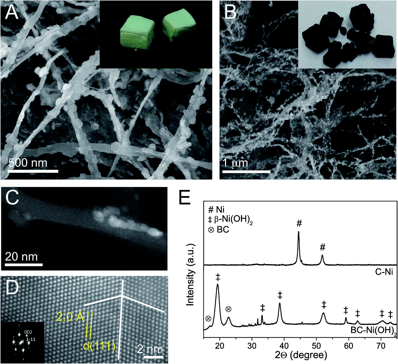 | ||
| Fig. 1 Microstructural characterization: SEM micrographs of BC–Ni(OH)2 (A) and C–Ni (B) with inset photographs of the respective foams. Cs-corrected STEM-HAADF micrographs of Ni NPs on a carbon fiber in sample C–Ni (C) and an atomic resolution observation of a Ni NP in sample C–Ni with the inset FFT pattern (D). The white lines indicate the twin boundary. XRD pattern of BC–Ni(OH)2 and C–Ni (E). | ||
The textural analysis of the C–Ni foams reveals a BET specific surface area of 61 m2 g−1 (ESI, Fig. S3†) and an apparent density of 11 kg m−3 at a porosity of 99%. Before pyrolysis BC–Ni(OH)2 has an apparent density of 8 kg m−3, which suggests that the foam only slightly collapsed during pyrolysis maintaining its original foam-like structure. Elemental analysis of C–Ni indicates a carbon content of 9–16 wt% and a Ni content of up to 89 wt% as determined by TXRF.
Detailed High-Resolution (HR) STEM investigation of C–Ni revealed a core–shell structure of the nanoparticles. The Ni core is covered by a 1.2 ± 0.4 nm thick, partially disordered shell (Fig. 2A) of nickel oxide/hydroxide as evidenced from Ni 2p core level X-ray photoemission spectroscopy (XPS) (ESI, Fig. S4A†). Indeed, Electron Energy Loss Spectroscopy (EELS) mapping across a nanoparticle indicates enhanced oxygen concentration at the particle surface layer, while the core, as already described in Fig. 1, is composed of pure Ni (ESI, Fig. S4B†). The fact that NiO does not appear in the diffractogram of C–Ni is a strong indication for a disordered crystal structure, which is also corroborated by O 1s core level XPS (ESI, Fig. S4C†) and Raman spectroscopy (Fig. 2B). The spectrum of C–Ni shows a strong one-phonon band of the longitudinal optical (LO) mode at 536 cm−1, attributed to crystalline defects in NiO.
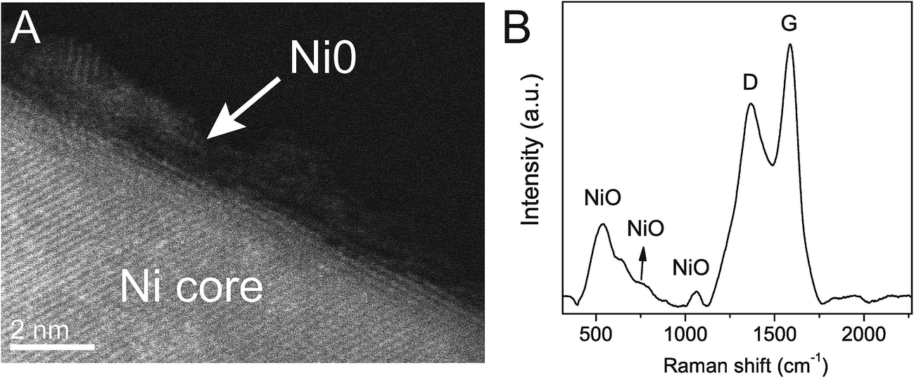 | ||
| Fig. 2 Cs-corrected STEM-HAADF micrograph of a Ni@NiO core@shell nanoparticle (A). Raman spectrum of C–Ni showing NiO bands and the D (sp3) and G (sp2) bands of carbon (B). | ||
Thermal analysis was conducted to elucidate the formation of the nickel nanoparticles by carbothermal reduction of Ni(OH)2 (ESI, Fig. S5†). The thermogravimetric analysis coupled with mass spectroscopy (TG-MS) of BC–Ni(OH)2 in nitrogen shows the evolution of CO, CO2, and larger cellulose decomposition products, respectively, (260 °C), the evolution of water (315 °C), and a further evolution of CO and CO2 (390 °C) (Fig. 3A). The differential scanning calorimetry (DSC) curve of BC–Ni(OH)2 shows a strong endothermic peak at 319 °C, an exothermic peak at 338 °C, and a second, weaker endothermic peak at 388 °C (Fig. 3B). The thermal transition at 319 °C can be attributed to the decomposition of nickel hydroxide to NiO under release of water in agreement with the TG-MS data. This transformation to the fcc NiO phase (JCPDS 78-0643) is also confirmed by XRD of a BC–Ni(OH)2 sample that was heated until 320 °C under N2 (Fig. 3C). The DSC peak at 388 °C is related to the transformation of NiO to metallic nickel as suggested by the diffractogram of the sample annealed at 380 °C, where the (111) and (200) reflections of fcc Ni appear (Fig. 3C). The formation of metallic nickel at such low temperatures is indeed extraordinary as will be discussed below.
 | ||
| Fig. 3 Study of carbothermal reduction of nickel: TG-MS curves of H2O, CO, and CO2 produced from BC (dashed lines) and BC–Ni (solid lines) under N2 atmosphere. (A) The existence and formation regimes of Ni(OH)2, NiO, and Ni are indicated. DSC curve of BC–Ni(OH)2 in nitrogen (B). XRD pattern (C) of BC–Ni(OH)2 annealed under nitrogen at 320 °C and 380 °C. The inset photograph in (C) shows the corresponding samples, where charring is manifested by the color change from brown to black with increased annealing temperature. | ||
In parallel to the nickel transformations the bacterial cellulose undergoes a carbonization process. The Raman spectrum in Fig. 2B shows the carbon D (1367 cm−1) and G (1586 cm−1) bands attributed to pyrolyzed cellulose in C–Ni. The G band corresponds to in-plane lattice vibrations of sp2 hybridized carbon atoms in graphene, while the D band originates from structural defects and sp3 hybridized carbon typically observed in graphene oxide.26 The band intensity ratio ID/IG together with the width of the G band give an estimate of the structural quality of the graphitic carbon layers.27 In C–Ni the ID/IG value is 0.78 and the FWHM (full width at half maximum) is 100 cm−1 for the G band and 185 cm−1 for the D band. Both findings suggest a significant amount of structurally ordered graphitic carbon similar to observations in graphene from pyrolyzed saccharides.19,28 Indeed, Cs-corrected TEM bright field (BF) investigations in Fig. 4A show the presence of graphene-like layers around the nanoparticles with a d(002) spacing of 3.6 Å similar to graphite. Interestingly, the graphitic layers only appear on the NP surface, while further away they are more disordered (ESI, Fig. S6†) and form a carbon matrix as can be observed in EELS maps (Fig. 4B). This observation is also supported by diffractograms of C–Ni that do not show any reflections of graphite (cf. Fig. 1E), which suggests that the graphitic carbon is disordered and the domain size is below the coherence length of the employed X-rays source. A lack of two-dimensional graphitic order is also suggested by the Raman spectrum of C–Ni, which shows the absence of the second-order 2D band attributed to the electron band structure of the graphene lattice (ESI, Fig. S7†).27 The composition of the carbon phase was further investigated by FTIR (ESI, Fig. S8†) and XPS revealing that sp3 C–C or C–H bonds represent about 32% of the carbon bonds, while approximately 53% of the carbon atoms are bonded to oxygen (Fig. 4C). Additionally, it has been found that approximately 15% of the carbon is sp2. The fact that graphitic carbon layers only appear in the immediate vicinity of the NPs may prompt the conjecture that Ni acts as catalyst in the graphitization of cellulose. In fact, it has been shown that Ni particles can catalyze the conversion of amorphous to graphitic carbon at temperatures of 550 °C resulting in disordered graphite layers on the particle surface.29,30 Indeed, in the present study, bacterial cellulose in presence of Ni(OH)2 decomposed about 70 °C below the decomposition temperature of pure bacterial cellulose, which is a strong indication of the catalytic activity of the in situ formed nickel species, i.e. NiO and Ni.22
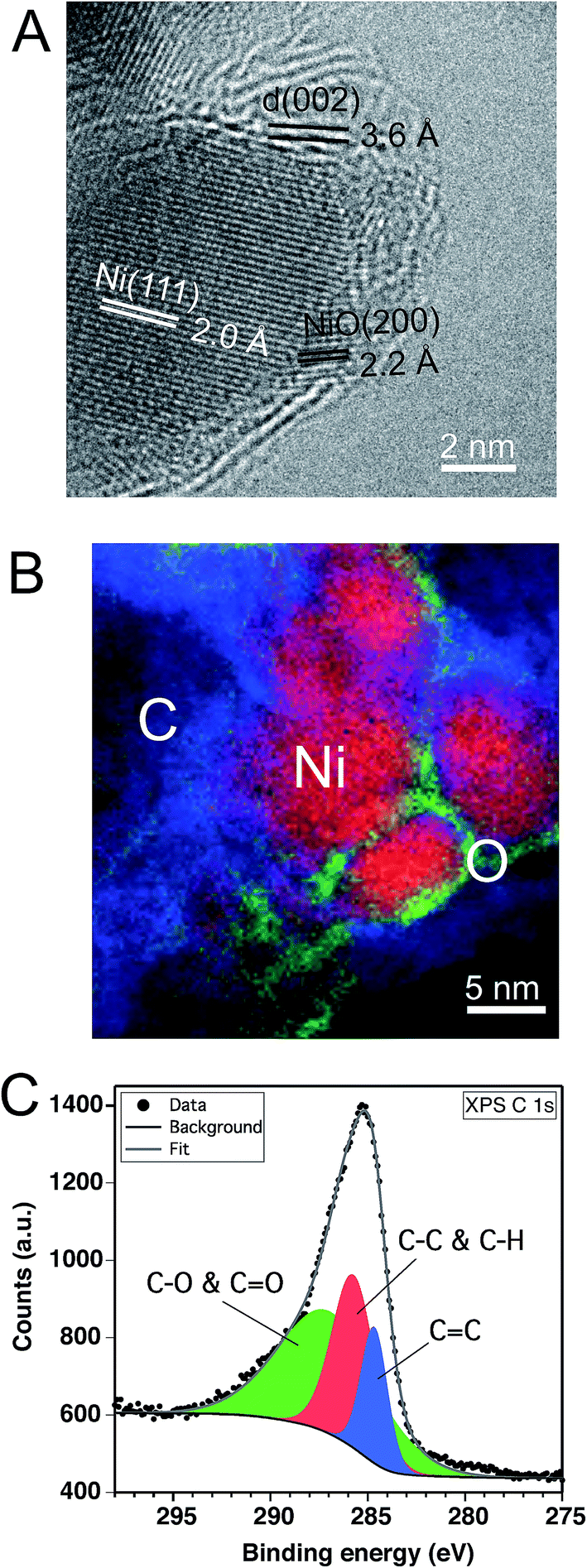 | ||
Fig. 4 Carbon layer characterization of C–Ni: TEM micrograph of a NiO@Ni NP covered by a carbon layer (A). EELS mapping of NiO@Ni NPs surrounded by carbon (B). Color code: red: Ni; green: O; blue: C. C 1s core level XPS spectrum of C–Ni including fitting curves of components located at 284.6 eV (C![[double bond, length as m-dash]](https://www.rsc.org/images/entities/char_e001.gif) C), 285.7 eV (C–C and C–H), and 287 eV (C–O and CO) (C). C), 285.7 eV (C–C and C–H), and 287 eV (C–O and CO) (C). | ||
Carbothermal reduction mechanism of BC–Ni(OH)2
A formation mechanism of the carbon–nickel hybrid based on the DSC, TG-MS and XRD results is proposed in the schematic of Fig. 5, where the interdependence of nickel reduction and cellulose transformation is depicted. The thermal decomposition of BC occurs around 260 °C, while nickel hydroxide dehydrates at 315 °C to NiO. At 340 °C decomposed cellulose is further transformed into carbon-rich char31,32 (cf. DSC, Fig. 3B) possibly activated by the presence of NiO as in pure bacterial cellulose this process does not occur (ESI, Fig. S9†). At 390 °C a further evolution of CO and CO2 occurs in BC–Ni(OH)2 but not in BC. This can be explained by a carbothermal reduction of NiO with carbon10 produced during charring of cellulose. Integration of the TG-MS peak at 390 °C gives a CO/CO2 ratio of 0.24 (ESI, Fig. S10†), which suggests that the solid state reaction| 2NiO + C → CO2 + 2Ni | (1) |
| NiO + CO → CO2 + Ni | (2) |
| CO2 + C → 2CO | (3) |
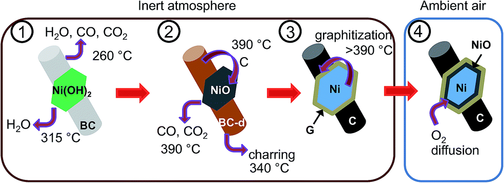 | ||
| Fig. 5 Formation mechanism of C–Ni: schematic showing the transformation of BC–Ni(OH)2 into C–Ni through various steps; the dehydration of Ni(OH)2, the decomposition of BC (BC-d), the carbothermal reduction of NiO, and the carbonization of BC (not drawn to scale). | ||
Indeed, thermodynamic calculations show that CO can easily reduce NiO at temperatures below 400 °C according to reaction (2).36 In fact, TG-MS revealed a CO/CO2 ratio (2.4 × 10⁻¹) that is a 100-fold higher than what is required to reduce NiO at 390 °C according to the Ellingham diagrams, viz. 2 × 10⁻³. In other words, BC–Ni(OH)2 generates sufficient CO to facilitate reaction (3) at 390 °C. On the other hand, reaction (3) is known to be catalyzed by nascent nickel and thus, may contribute by auto-catalyzing the reduction of NiO.
The role of bacterial cellulose in the carbothermal reduction of NiO appears to be important as inferred by comparing the process with glucose, the monomer in cellulose. Precipitated Ni(OH)2 was mechanically mixed with glucose at a 1/1 wt ratio and subjected to the same pyrolysis conditions as BC–Ni(OH)2. The X-ray diffractogram (ESI, Fig. S11†) of the product clearly showed the presence of NiO, amounting to approx. 15% with respect to Ni as per peak integration, while in case of BC all NiO was reduced to Ni. This finding suggests that the carbothermal reduction with BC was more efficient as with glucose, which is possibly attributed to the intimate contact of the Ni(OH)2 nanoparticles precipitated directly on the BC fibers (cf. Fig. 1C).
Concerning the graphitic carbon layer on the surface of the nanoparticles it is suggested that the amorphous carbon produced from charred cellulose is graphitized by the in situ formed Ni0 (vide supra).20,22 But it has also been shown that re-deposition of volatile aromatic and aliphatic products from saccharide or biomass pyrolysis can form graphene-like structures upon adsorption on solids.37 A similar mechanism may also simultaneously operate in the present case and thus, contribute to the formation of the carbonaceous layers on the nickel NPs. However, the disordered and presumably porous microstructure of this carbon layer is likely to allow diffusion of oxygen to the Ni surface in ambient atmosphere and thus, lead to the observed NiO shell between the metallic Ni core and the external carbon layer.
Synthesis and characterization of carbon–iron hybrids
The here described carbothermic synthesis method for the production of carbon–nickel hybrids could also be applied to other transition metal oxides with ΔG° > ΔG°(CO2), that is, above the CO2 (2CO + O2 → 2CO2) line in the Ellingham diagram. In this regard, oxides of Co, Fe, Sn, Cu, or Mo should be reduced. Exemplarily we corroborated this possibility by successfully extending the method to Fe(III)-hydroxide. β-FeO(OH) (JCPDS 34-1266) was precipitated on BC (ESI, Fig. S12†) and was reduced to Fe/γ-Fe2O3 according to XRD (Fig. 6A). Quantitative analysis based on XRD peak integration revealed a high Fe/γ-Fe2O3 ratio of 27/73, while the temperature of the metal reduction is as low as 640 °C (ESI, Fig. S13†). The Scherrer size of the Fe phase is around 35 nm and consistent with nanoparticles observed in Fig. 6B.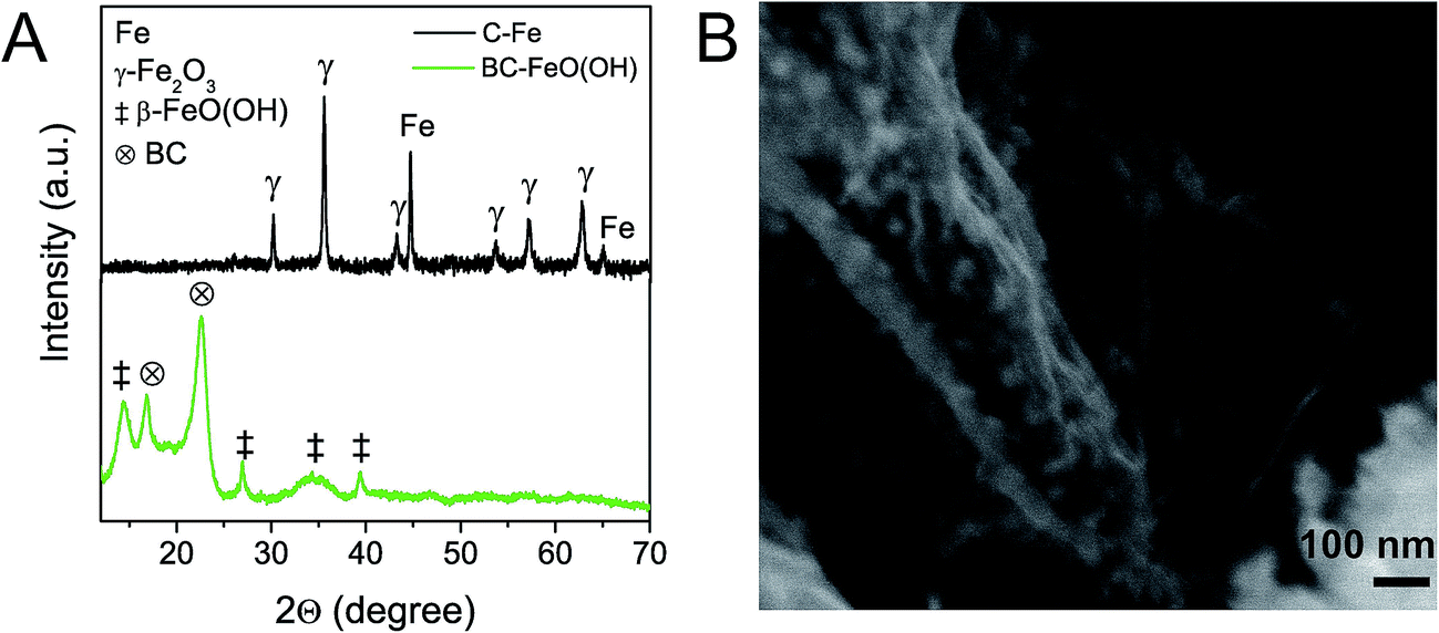 | ||
| Fig. 6 XRD pattern (A) of BC–FeO(OH) and C–Fe, which is obtained from pyrolysis of BC–FeO(OH) at 650 °C. The C–Fe pattern shows reflections attributed to γ-Fe2O3 and metallic Fe. SEM micrograph of C–Fe (B). | ||
Functional properties of C–Ni
The functional properties of the carbon–metal hybrids were exemplarily shown for C–Ni, which displayed an electrical conductivity of 0.3 S m−1 and magnetic properties as a consequence of the formation of the metal nanoparticles. For instance, the magnetization cycles, M(H), of C–Ni revealed hysteresis loops typical of a ferromagnetic (FM) material (Fig. 7), while the temperature dependent magnetization, M(T), (ESI, Fig. 14†) suggests magnetic anisotropy of the FM phase. The saturation magnetization (Ms) at 300 K is 40 emu gNi−1. This value is lower than the Ms of bulk nickel (55 emu g−1), however this reduction in Ms is commonly observed for nanosized magnetic particles.38 This combination of electric conductivity and magnetic permeability can be useful for the production of electromagnetic interference shields.13 Moreover, preliminary tests have shown that the generation of the porous, graphitic fiber network can result in very low total reflectance in the visible light range, which is interesting for efficient light absorption in solar energy applications. | ||
| Fig. 7 Magnetization cycles M(H) of C–Ni at 4 K and 300 K. The coercivity Hc of C–Ni is 60 Oe at 300 K and 600 Oe at 4 K, which is consistent with the presence of ferromagnetic Ni. | ||
Conclusions
In summary, we have shown that highly crystalline nickel nanoparticles can be synthesized at a remarkably low temperature of 390 °C with the concomitant generation of graphitic carbon nanofiber foams produced from bacterial cellulose networks. These Ni0 nanoparticles are homogeneously distributed within the carbon aerogel materials. A reaction path was identified that leads from dehydration of the nickel hydroxide to nickel oxide and finally to metallic nickel after carbothermic reaction with the charred cellulose. Our study suggests the combination of a solid state reaction of carbon and NiO with a gas phase reaction involving CO as reductant, which is generated during pyrolysis of bacterial cellulose. On the other hand, the nascent nickel nanoparticles catalyze the formation of graphitic carbon surrounding the nanoparticles. The low temperature process indicates a graphitization mechanism different from the dissolution/crystallization mechanism, for which more work is required for the elucidation of the exact mechanism. Nevertheless, the here proposed synthesis route is versatile and was easily extended in a first attempt to iron, hinting the possible applicability to other related transition metals. The nanostructured carbon–nickel foams simultaneously showed electrical conductivity and ferromagnetic behavior, which could be exploited in the future as sustainable material in diverse advanced applications.Conflicts of interest
There are no conflicts to declare.Acknowledgements
The authors thank A. Varela and I. Poveda (UAM-Sidi) (SEM), the ICMM thermal analysis service, Prof. A. de Andrés (Raman measurements), R. Barrio (BET measurements), Prof. M. García (magnetic measurements), as well as Prof. M. Camblor, Dr Á. Blanco and Dr R. Jiménez for fruitful discussions. Financial support from CICYT (projects MAT2012-31759, MAT2015-71117-R). BW acknowledges an IJCI contract.References
- X.-H. Li and M. Antonietti, Chem. Soc. Rev., 2013, 42, 6593–6604 RSC.
- J. Liu, N. P. Wickramaratne, S. Z. Qiao and M. Jaroniec, Nat. Mater., 2015, 14, 763–774 CrossRef CAS PubMed.
- Y. Chang, M. Antonietti and T.-P. Fellinger, Angew. Chem., Int. Ed., 2015, 54, 5507–5512 CrossRef CAS PubMed.
- Z.-Y. Yu, Y. Duan, M.-R. Gao, C.-C. Lang, Y.-R. Zheng and S.-H. Yu, Chem. Sci., 2017, 8, 968–973 RSC.
- J. Tuček, Z. Sofer, D. Bouša, M. Pumera, K. Holá, A. Malá, K. Poláková, M. Havrdová, K. Čépe, O. Tomanec and R. Zbořil, Nat. Commun., 2016, 7, 12879 CrossRef PubMed.
- B. Li, H. Nam, J. Zhao, J. Chang, N. Lingappan, F. Yao, T. H. Lee and Y. H. Lee, Adv. Mater., 2017, 29, 1605083 CrossRef PubMed.
- Z. Zhuang, S. A. Giles, J. Zheng, G. R. Jenness, S. Caratzoulas, D. G. Vlachos and Y. Yan, Nat. Commun., 2016, 7, 10141 CrossRef CAS PubMed.
- J. M. Lee, J. Lim, N. Lee, H. I. Park, K. E. Lee, T. Jeon, S. A. Nam, J. Kim, J. Shin and S. O. Kim, Adv. Mater., 2015, 27, 1519–1525 CrossRef CAS PubMed.
- K. J. Lee, S. Choi, S. Park and H. R. Moon, Chem. Mater., 2016, 28, 4403–4408 CrossRef CAS.
- Y. Shen, J. Mater. Chem. A, 2015, 3, 13114–13188 CAS.
- J. Ren, M. Antonietti and T.-P. Fellinger, Adv. Energy Mater., 2015, 5, 1401660 CrossRef.
- W. Xi, Z. Ren, L. Kong, J. Wu, S. Du, J. Zhu, Y. Xue, H. Meng and H. Fu, J. Mater. Chem. A, 2016, 4, 7297–7304 CAS.
- G. Li, L. Wang, W. Li and Y. Xu, ChemPhysChem, 2015, 16, 3458–3467 CrossRef CAS PubMed.
- X. Xu, J. Zhou, D. H. Nagaraju, L. Jiang, V. R. Marinov, G. Lubineau, H. N. Alshareef and M. Oh, Adv. Funct. Mater., 2015, 25, 3193–3202 CrossRef CAS.
- Z.-Y. Wu, C. Li, H.-W. Liang, J.-F. Chen and S.-H. Yu, Angew. Chem., 2013, 125, 2997–3001 CrossRef.
- J. Zhang, B. Li, L. Li and A. Wang, J. Mater. Chem. A, 2016, 4, 2069–2074 CAS.
- E. Jazaeri and T. Tsuzuki, Cellulose, 2013, 20, 707–716 CrossRef CAS.
- L. Wang, C. Schütz, G. Salazar-Alvarez and M.-M. Titirici, RSC Adv., 2014, 4, 17549 RSC.
- E. Ruiz-Hitzky, M. Darder, F. M. Fernandes, E. Zatile, F. J. Palomares and P. Aranda, Adv. Mater., 2011, 23, 5250–5255 CrossRef CAS PubMed.
- J. Hoekstra, A. M. Beale, F. Soulimani, M. Versluijs-Helder, D. van de Kleut, J. M. Koelewijn, J. W. Geus and L. W. Jenneskens, Carbon, 2016, 107, 248–260 CrossRef CAS.
- S. Glatzel, Z. Schnepp and C. Giordano, Angew. Chem., Int. Ed., 2013, 52, 2355–2358 CrossRef CAS PubMed.
- J. Hoekstra, A. M. Beale, F. Soulimani, M. Versluijs-Helder, J. W. Geus and L. W. Jenneskens, J. Phys. Chem. C, 2015, 119, 10653–10661 CAS.
- B. Wicklein and G. Salazar-Alvarez, J. Mater. Chem. A, 2013, 1, 5469–5478 CAS.
- M. Tabuchi, Nat. Biotechnol., 2007, 25, 389–390 CrossRef CAS PubMed.
- S. Li and J. Huang, Adv. Mater., 2016, 28, 1143–1158 CrossRef CAS PubMed.
- K. N. Kudin, B. Ozbas, H. C. Schniepp, R. K. Prud'homme, I. Aksay and R. Car, Nano Lett., 2008, 8, 36–41 CrossRef CAS PubMed.
- A. C. Ferrari and D. M. Basko, Nat. Nanotechnol., 2013, 8, 235–246 CrossRef CAS PubMed.
- M. Latorre-Sánchez, A. Primo and H. García, Angew. Chem., Int. Ed., 2013, 52, 11813–11816 CrossRef PubMed.
- R. Lamber, N. Jaeger and G. Schulz-Ekloff, Surf. Sci., 1988, 197, 402–414 CrossRef CAS.
- S. Chen, W. Xiong, Y. S. Zhou, Y. F. Lu and X. C. Zeng, Nanoscale, 2016, 8, 9746–9755 RSC.
- S. Soares, G. Camino and S. Levchik, Polym. Degrad. Stab., 1995, 49, 275–283 CrossRef CAS.
- B. Wicklein, D. Kocjan, F. Carosio, G. Camino and L. Bergström, Chem. Mater., 2016, 28, 1985–1989 CrossRef CAS.
- T. G. Devi and M. P. Kannan, Energy Fuels, 2007, 21, 596–601 CrossRef CAS.
- S. K. Sharma, F. J. Vastola and P. L. Walker, Carbon, 1997, 35, 529–533 CrossRef CAS.
- S. Vijayan, R. Narasimman and K. Prabhakaran, Mater. Lett., 2016, 181, 268–271 CrossRef CAS.
- Q. Li, L. S. Wang, B. Y. Hu, C. Yang, L. Zhou and L. Zhang, Mater. Lett., 2007, 61, 1615–1618 CrossRef CAS.
- A. Gómez-Avilés, M. Darder, P. Aranda and E. Ruiz-Hitzky, Angew. Chem., Int. Ed., 2007, 46, 923–925 CrossRef PubMed.
- M. Seifollahi Bazarjani, M. M. Müller, H.-J. Kleebe, Y. Jüttke, I. Voigt, M. Baghaie Yazdi, L. Alff, R. Riedel and A. Gurlo, ACS Appl. Mater. Interfaces, 2014, 6, 12270–12278 CAS.
Footnote |
| † Electronic supplementary information (ESI) available. See DOI: 10.1039/c7ra07534k |
| This journal is © The Royal Society of Chemistry 2017 |