
 Open Access Article
 This Open Access Article is licensed under a
 Creative Commons Attribution 3.0 Unported Licence
An autonomous electrochemically-actuated microvalve for controlled transport in stand-alone microfluidic systems†
T. Watanabe,
G. C. Biswas,
E. T. Carlen and
H. Suzuki*
Graduate School of Pure and Applied Sciences, University of Tsukuba, 1-1-1 Tennodai, 305-8573 Tsukuba, Japan. E-mail: hsuzuki@ims.tsukuba.ac.jp
First published on 10th August 2017
Abstract
We present a new electrochemically-actuated microvalve that does not require an external power source and is well-suited for autonomous stand-alone microfluidic systems. The microvalve is composed of a single bi-metallic Zn/Pt electrode, where the Pt region of the electrode is located in a solution microchannel and the Zn/Pt region of the electrode is located in a separated control microchannel. The Pt electrode is covered with a hydrophobic self-assembled monolayer (SAM) that stops solution flow in the solution microchannel, hence is normally-closed. The microvalve is opened by introducing an electrolyte into the control microchannel, which oxidizes the Zn layer of the Zn/Pt electrode and forces a negative mixed potential of the entire electrode. The negative mixed potential is sufficient to remove the SAM from the Pt electrode through reductive desorption, thus opening the microvalve and allowing the solution to flow. Microvalves based on this actuation mechanism can be used to initiate solution flow in any arbitrary microchannel configuration and significantly simplify peripheral equipment requirements.
Introduction
Microfluidic systems are becoming an indispensable platform for on-chip analysis and processing of chemical and biological solutions. Currently, solution transport in most microfluidic systems relies on external instruments, such as pumps and power sources. However, some critical applications, such as point-of-care testing (POCT), require small stand-alone systems with simple operation.1,2 For this purpose, miniaturization of all system components, including pumps and valves, remains a critical issue. To meet this demand, a variety of microfluidic components based on microfabrication techniques have been reported.3–8 However, device structure and function tend to be complicated making integration of many components for multiplexed solution processing problematic.To control solution transport in microchannels, we previously reported a simple microvalve based on active switching of the hydrophobicity of an electrode surface.9 The microvalve is based on a hydrophobic self-assembled monolayer (SAM) formed on a platinum electrode (SAM-Pt microvalve) in a microchannel. The SAM-Pt electrode stops a solution that moves by capillary action and can be opened upon the application of an electric potential to the electrode that removes the SAM. The simple structure and function facilitated its integration in many different microchannel networks.
Previously reported microvalves, including ours described above, are switched by the application of electrical signals. If this switching can be done autonomously, the system operation can be significantly simplified. In an attempt to realize this, chemically-actuated microvalves that employ spontaneous volumetric change of a hydrogel have been reported.10–12 Autonomous microfluidic devices based on capillary action have also been reported.13–19 However, even with these techniques, highly controlled and multiplexed solution transport is not straightforward.
In this paper, we present a new electrochemically-actuated microvalve that is based on our SAM-Pt microvalve. However, in this case, the electric potential required for opening the microvalve is generated by the mixed potential of a single bi-metallic Zn/Pt electrode. The SAM-Pt part of the electrode is located in a solution microchannel and the Zn/Pt part of the electrode is located in a separated control microchannel. Any aqueous solution can be used in the solution microchannel. An aqueous solution containing electrolytes introduced into the control microchannel oxidizes the Zn layer, which subsequently produces a negative mixed potential of the entire electrode. The mixed potential mechanism generated on a single electrode occurs when multiple redox reactions proceed simultaneously as found in metal corrosion and electroless plating.20,21 The potential is determined by the condition that the sum of all currents due to anodic and cathodic reactions is zero. The negative mixed potential generated at the SAM-Pt part of the electrode causes the reductive desorption of the SAM, thus opening the microvalve and allowing the solution to flow. The timing of the microvalve switching can be controlled by positioning the Zn/Pt electrodes at appropriate locations in the control microchannel and can be used to program the opening of many microvalves.22
Experimental
Reagents and materials
Reagents and materials used for microfabrication were obtained from the following commercial sources: glass wafers (#7740, 3 inch, 500 μm thick) from Corning Japan (Tokyo, Japan); positive photoresist (S1818) from Rohm and Haas Japan (Tokyo, Japan); thick-film photoresist, SU-8 25, from MicroChem (Newton, MA, USA); prepolymer solution of PDMS, KE-1300T, from Shin-Etsu Chemical (Tokyo, Japan); 1-hexanethiol used for the SAM from Wako Pure Chemical Industries (Osaka, Japan); agarose L, from Nippon Gene (Tokyo, Japan). Other reagents were purchased from Wako Pure Chemical Industries, Osaka, Japan, unless otherwise noted. To visualize the movement of solutions, a phosphate buffer solution (pH 9.0) containing 3 M KCl and 1 mM fluorescein sodium salt (uranine) was used. Solutions were prepared with deionized water (resistivity 18.2 MΩ cm at 25 °C, Milli-Q).Microfabrication
The microvalves were microfabricated on glass substrates and subsequently aligned and bonded to PDMS microchannels. Metal electrodes were formed on the glass substrates using metal sputtering deposition and patterning with contact microlithography and lift-off. The Pt electrode was deposited on the glass substrate with a Cr adhesion layer. Following the formation of the Pt electrode, the SAM was then formed on part of the Pt electrode that was located in the solution microchannel. Also, the Zn layer was deposited on the Pt electrode in the control microchannel (see below). Microchannels were formed in a PDMS layer by replica molding using a template formed with a thick-film photoresist (SU-8 25). The height of all microchannels was 100 μm. Solution inlets, outlets, and air-release holes were formed at appropriate locations in the PDMS layer by hole punching. The SAM-Pt electrodes were 100 μm long along the direction of the microchannel. The PDMS layer was bonded to the glass substrate after aligning the electrodes and microchannel patterns. By applying slight pressure to the PDMS/glass composite, sufficient sealing was achieved.SAM formation
The SAM was selectively formed on the region of the Pt electrode located in the solution microchannel using three steps. First, the Pt electrode was cleaned in a solution containing deionized water, 25% NH3 and 30% H2O2 in a 4![[thin space (1/6-em)]](https://www.rsc.org/images/entities/char_2009.gif) :1:1 ratio. Next, the Pt electrode was partially covered with a photoresist (S1818) layer and the exposed Pt region (located in the solution microchannel) was further cleaned by potential cycling (∼10 times) in a potential range of −1.0 to +1.0 V (vs. Ag/AgCl/sat. KCl) in a 0.1 M KCl solution. Finally, the cleaned electrode was dried by nitrogen gas and was immediately immersed in an aqueous 1 mM 1-hexanethiol solution containing 0.1 M ethanol for 5 min. Following the formation of the SAM-Pt electrode, the protective photoresist layer was removed with acetone and the surface was rinsed in pure ethanol and dried by nitrogen gas. The PDMS microchannel layer was then aligned and bonded to the glass substrate, as described above.
:1:1 ratio. Next, the Pt electrode was partially covered with a photoresist (S1818) layer and the exposed Pt region (located in the solution microchannel) was further cleaned by potential cycling (∼10 times) in a potential range of −1.0 to +1.0 V (vs. Ag/AgCl/sat. KCl) in a 0.1 M KCl solution. Finally, the cleaned electrode was dried by nitrogen gas and was immediately immersed in an aqueous 1 mM 1-hexanethiol solution containing 0.1 M ethanol for 5 min. Following the formation of the SAM-Pt electrode, the protective photoresist layer was removed with acetone and the surface was rinsed in pure ethanol and dried by nitrogen gas. The PDMS microchannel layer was then aligned and bonded to the glass substrate, as described above.
Zn/Pt electrode
Zn was deposited on the bare Pt layer in the control microchannels by applying a constant current (100 mA cm−2) for 20 s in a stirred solution containing 1.8 M ZnCl2 and 4.9 M NH4Cl at 25 °C using a galvanostat (HA-151, Hokuto Denko, Tokyo, Japan). The area of the Zn layer varied from 0.4 mm2 to 3.6 mm2 depending on the device.Microvalve operation
Fig. 1 shows the operation of the microvalve starting at the normally-closed state. A solution introduced into the solution microchannel stops at the SAM-Pt microvalve, as shown in Fig. 1A. The motive force for the transport of solutions in the microchannels is by capillary action due to the hydrophilic surface of the glass substrate. An electrolyte introduced to the control microchannel wets the Zn/Pt electrode and results in the generation of a negative mixed potential of the entire electrode that is sufficient to remove the SAM by reductive desorption. As a result, the microvalve opens and the solution moves over the hydrophilic Pt electrode and throughout the solution microchannel (Fig. 1B). A liquid junction between the solution and electrolyte microchannels, which is composed of an agarose gel and an electrolyte, is necessary to maintain electrical continuity between the electrolyte and solution without mixing.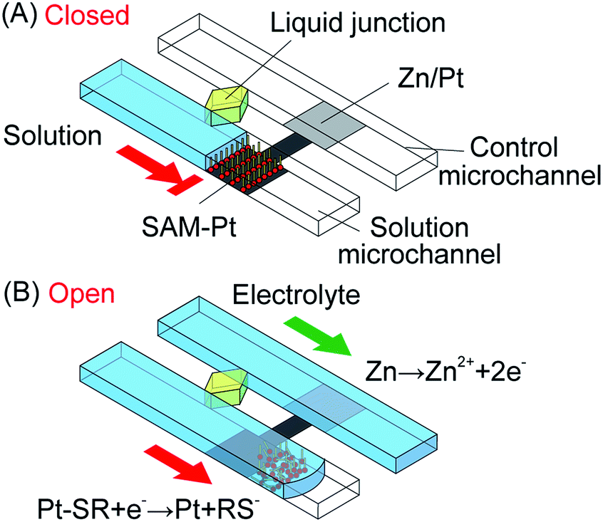 | ||
| Fig. 1 (A) The microvalve consists of a SAM-Pt electrode in the solution microchannel and a Zn/Pt electrode in the control microchannel, where the Pt is a continuous layer. An aqueous solution introduced into the solution microchannel stops at the normally-closed SAM-Pt electrode. (B) When an electrolyte in the control microchannel wets the Zn/Pt electrode, the microvalve opens allowing the solution to flow. | ||
Fig. 2 shows the polarization curves of the Zn/Pt electrode. P1 and P2 indicate the mixed potential when the microvalve is closed and open, respectively. When a solution is stopped at the SAM-Pt electrode, in the solution microchannel, the mixed potential of the electrode settles to a value determined by unidentified anodic and cathodic reactions (P1 in Fig. 2). An electrolyte introduced into the control microchannel wets the Zn/Pt electrode and dissolution of the Zn layer (anodic reaction) occurs. The mixed potential of the entire electrode shifts in the negative direction and desorption of SAM (cathodic reaction) occurs (P2 in Fig. 2), as previously described.
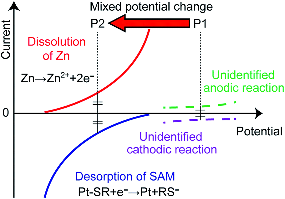 | ||
| Fig. 2 Polarization curves and the mixed potential. P1 indicates the mixed potential of the electrode when the microvalve is closed. P2 indicates the mixed potential when the microvalve opens. | ||
Results and discussion
Fig. 3 shows the change in the mixed potential of the electrode recorded after solutions were sequentially introduced into the solution and control microchannels. A liquid-junction Ag/AgCl reference electrode (Horiba, 2060A-10T) was inserted in the reservoir of the solution microchannel, and the potential of the SAM-Pt electrode was measured with respect to the reference electrode. First, the solution in the solution microchannel stops at the edge of the SAM-Pt electrode with a mixed potential of approximately +0.4 V (vs. Ag/AgCl/sat. KCl). Next, when an electrolyte introduced into the control microchannel wets the Zn/Pt part of the electrode, the mixed potential of the electrode abruptly changes to approximately −1.0 V (vs. Ag/AgCl/sat. KCl). Finally, accompanying the change of the mixed potential, the SAM-Pt microvalve opens and the solution moves into the solution microchannel.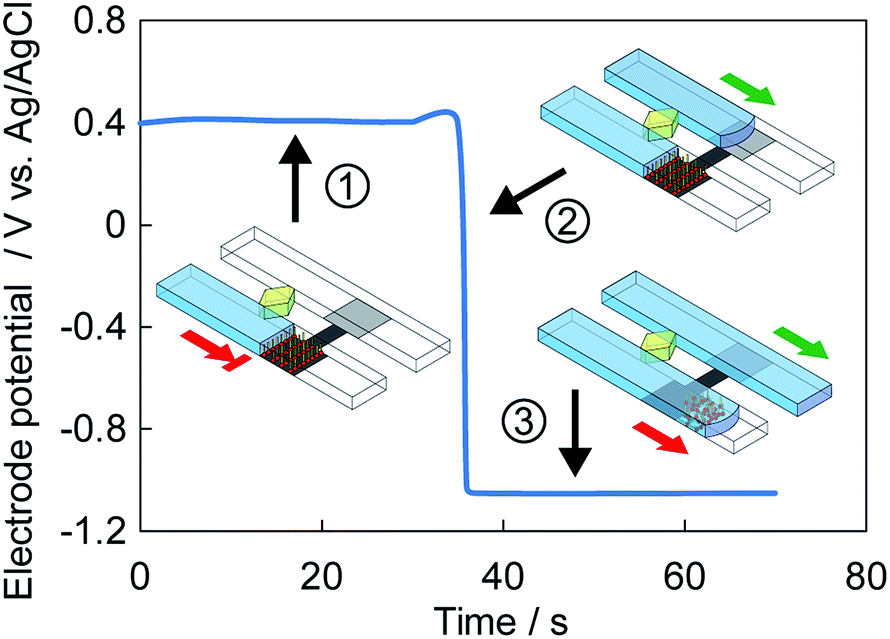 | ||
| Fig. 3 Mixed potential change of the electrode accompanying an electrolyte wetting the Zn/Pt part of the electrode in the control microchannel. The microvalve switching states are shown with depictions of the solution and electrolyte in each microchannel. State 1: normally-closed microvalve, state 2: electrolyte oxidation of the Zn layer forces a negative mixed electrode potential, and state 3: microvalve opens. | ||
The microvalve configuration is well-suited for multiplexed processing of solutions. We demonstrate the functionality of the new SAM-Pt microvalve using different solution processing systems. Fig. 4 demonstrates timed delivery of solutions from reservoirs SR1–SR3. In the system shown in Fig. 4A, solutions in reservoirs SR1–SR3 are delivered sequentially as the electrolyte from control reservoir CR1 wets each Zn/Pt electrode. The solution microchannels (SMCs) extend vertically with respect to the horizontal control microchannel (CMC). The Zn/Pt electrodes are located in the CMC and the SAM-Pt electrodes are located at the exit of the solution reservoirs SR1–SR3 in the SMCs. The solutions in the reservoirs did not move before the electrolyte reached the corresponding Zn/Pt electrode. Once the electrolyte wetted the Zn layer, the connected microvalves opened and liquid columns in the SMCs moved sequentially past the microvalve. Alternatively, in the system shown in Fig. 4B, one Zn/Pt electrode in the CMC controls three SAM-Pt electrodes in the SMCs. In this case, all the microvalves open simultaneously in parallel when the electrolyte in the CMC reaches the Zn/Pt electrode. Note the lengths of the solution columns in all of the SMCs were the same when the image was recorded.
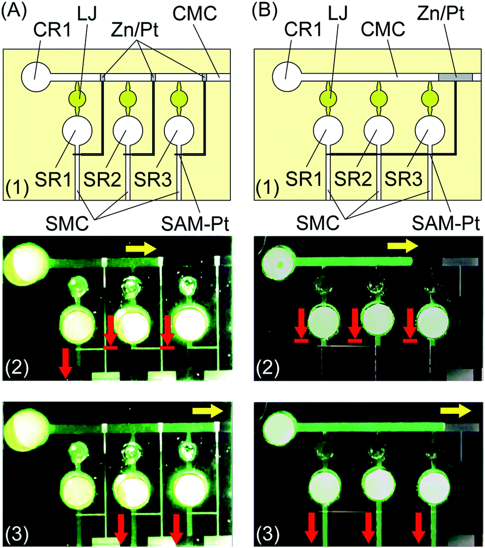 | ||
| Fig. 4 Solution distribution device. (A) Sequential distribution, (A1) schematic of system, (A2) microvalve 1 is open and microvalves 2 and 3 are closed, (A3) all microvalves are open. (B) Parallel distribution, (B1) schematic of system, (B2) all microvalves are closed, (B3) all microvalves are open. The yellow arrows indicate the position of the electrolyte and the red arrows indicate the positions of the solutions. SMC: solution microchannel, CMC: control microchannel, LJ: liquid junction, SR1–SR3: solution reservoirs, CR1: control reservoir. | ||
In these systems, the speed of the solution in the straight CMC slows down as the solution moves forward by capillary action. Therefore, opening the microvalves at fixed intervals for a large number of microchannels is difficult. For more precise control of solution delivery, a row of short CMCs of the same length can be used, as shown in Fig. 5. This system has four SMCs and four CMCs. Each Zn/Pt electrode in the corresponding CMC is connected to a SAM-Pt microvalve in the corresponding SMC. A SAM-Pt microvalve is located at the exit of the solution reservoir of the next CMC. Prior to use, reservoirs CR2–CR4 connected to the CMCs were filled with electrolyte solutions (Fig. 5B). The solutions stopped temporarily at the microvalves located at the exit of each reservoir. When the final electrolyte was introduced into reservoir CR1 (Fig. 5C), and the solution arrived at the Zn/Pt electrode (Fig. 5D), the microvalves in the first SMC and second CMC opened. The electrolyte in the third CMC then moved to the next Zn/Pt electrode and the microvalve in the second SMC opened (Fig. 5E). Accompanying this, the microvalves in the fourth CMC and third SMC opened (Fig. 5F). Finally, the microvalve in the fourth SMC opened (Fig. 5G). The same steps can be repeated with more reservoirs and microchannels. The array of equal-length CMCs, with SAM-Pt and Zn/Pt electrodes, facilitates more precise and reliable control of solution delivery.
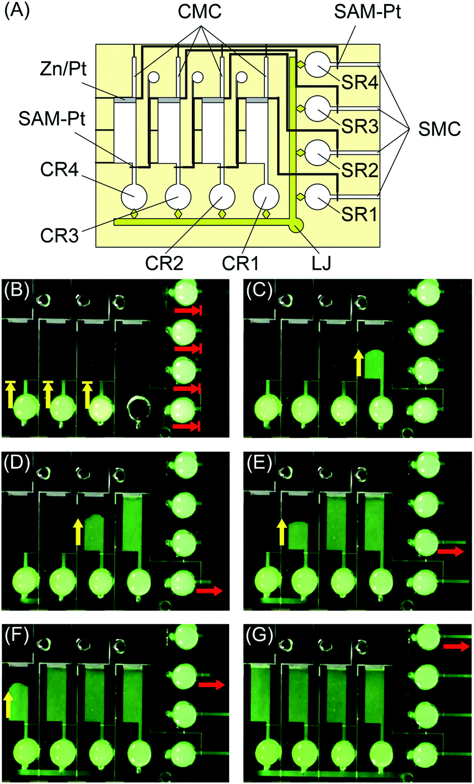 | ||
| Fig. 5 Solution delivery with controlled sequential timing using an array of CMCs. (A) Schematic of system. (B)–(G) Solutions in the SMCs (indicated by red arrows) move sequentially lagging the movement of the electrolytes in the CMCs (indicated by yellow arrows). CMC: control microchannel, SMC: solution microchannel, LJ: liquid junction, SR1–SR4: solution reservoirs, CR1–CR4: control reservoirs. | ||
The new microvalves can be arranged in many different configurations depending on the application. For example, binary logic operations can be performed. A 1-bit binary adder is shown in Fig. 6. The system consists of input reservours (IRs) that represent binary inputs A and B. The system outputs are connected to the output reservoirs (ORs) and output microchannels (OMCs), with the corresponding results shown in the form of digits 0, 1, and 2. Zn/Pt electrodes are located in the input microchannels (IMCs), and the SAM-Pt microvalves are located in the OMCs. Air-release holes are at the end of the IMCs. Prior to use, the ORs are filled with solutions. By selecting the IR of inputs A and B, the addition operation is performed. When A = 0 and B = 0, the result is OMC = 0, when A = 0 and B = 1 or A = 1 and B = 0, the result is OMC = 1, and when A = 1 and B = 1, the result is OMC = 2. Other logical operations can be performed using this approach. Fig. S1† shows examples of 2-bit binary OR and AND operations. These results show that these systems based on the electrochemically-actuated microvalve can be applied to microfluidics-based information processing.
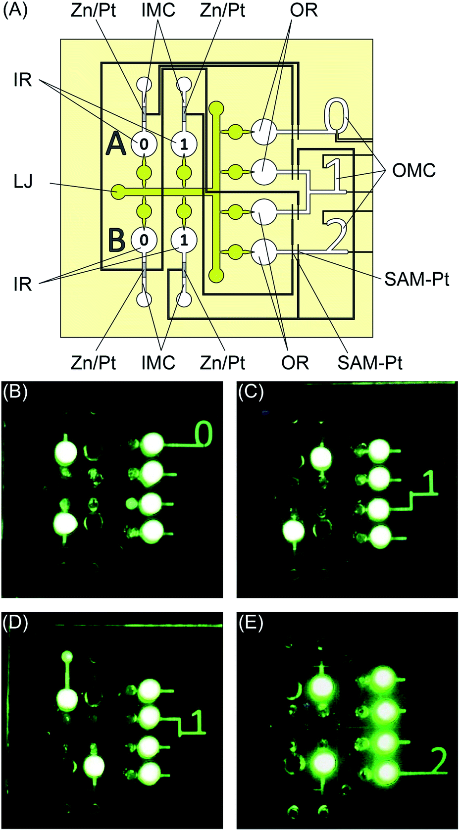 | ||
| Fig. 6 1-bit binary adder system. (A) Schematic of system. (B) A = 0, B = 0, OMC = 0. (C) A = 1, B = 0, OMC = 1. (D) A = 0, B = 1, OMC = 1. (E) A = 1, B = 1, OMC = 2. IMC: input microchannel, OMC: output microchannel, IR: input reservoir, OR: output reservoir, LJ: liquid junction. | ||
The final example we present is a microfluidics-based display enabled by the new microvalves. Fig. 7 shows a microfluidics-based display that writes out the Chinese symbol meaning “trip” in the correct stroke order. The system has two SMCs connected by a liquid junction (LJ). In this case, the SMCs are also used as a LJ. Air-release holes are placed at the ends of the microchannels. The SAM-Pt and Zn/Pt electrodes are located at the top and bottom of each character, which indicates the progress of each display step. Fig. S2† shows a similar microfluidics-based display for Roman characters.
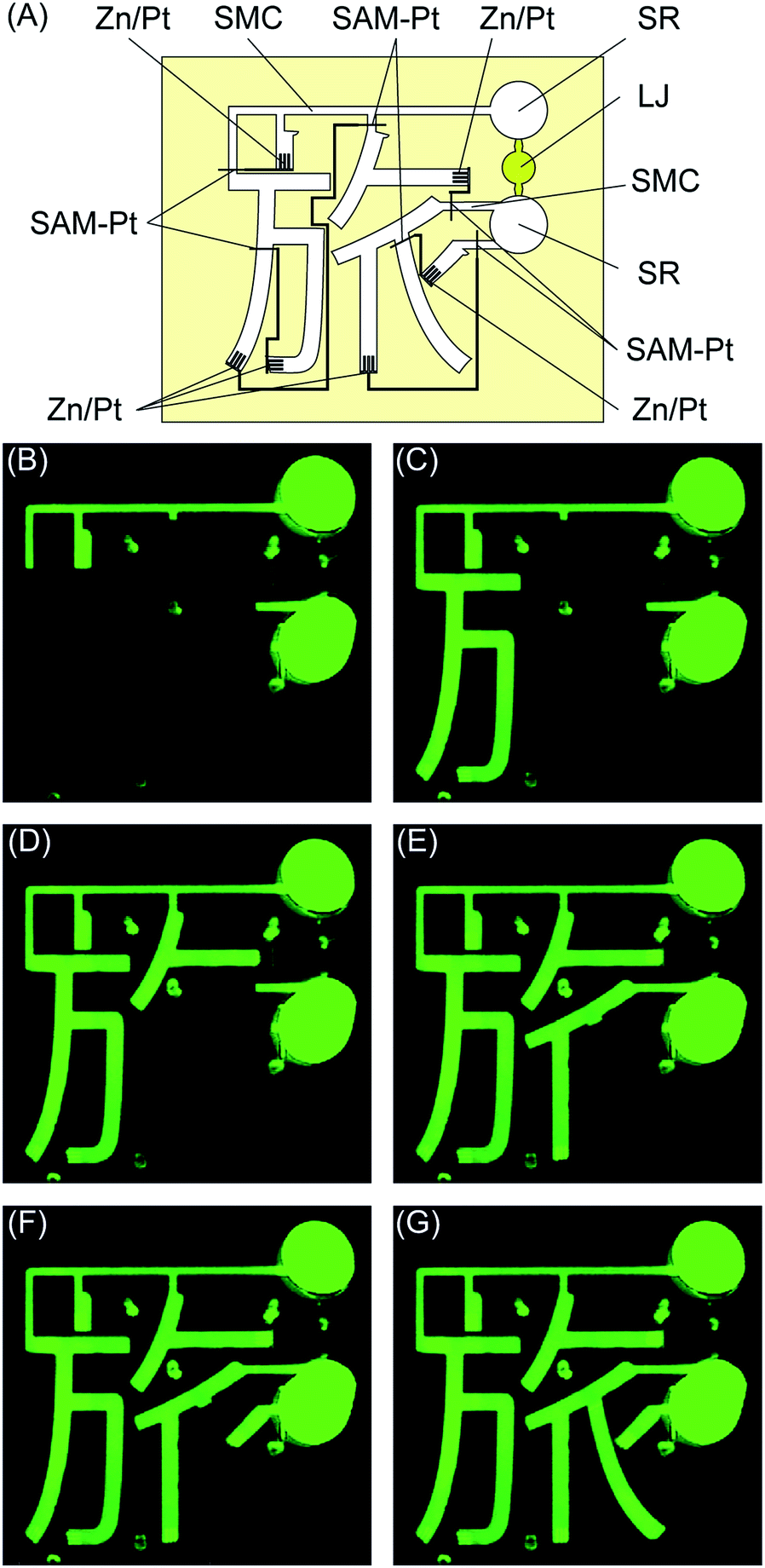 | ||
| Fig. 7 Microfluidics-based character display system. (A) Schematic of system. (B)–(G) Characters are displayed sequentially in the correct stroke order. | ||
In these examples, we demonstrated the functionality of the new SAM-Pt microvalve with an electrochemical actuation mechanism. These simple one-time use microvalves are well-suited for disposable lab-on-a-chip systems that process solutions that are driven by capillary-action fluid force.
Conclusions
We presented a new electrochemically-actuated microvalve that does not require an external power source. The microvalve is based on a hydrophobic SAM-Pt electrode in a solution microchannel that is switched open by a negative mixed potential generated by the oxidation of a Zn/Pt electrode located in a separated control microchannel. Solution transport by capillary action stops at the normally-closed SAM-Pt electrode microvalve. The solution transport resumes when an electrolyte in a control microchannel wets the Zn/Pt electrode that results in a negative mixed potential and removal of the hydrophobic SAM, thus exposing the underlying hydrophilic Pt electrode. Any aqueous solution can be used in the solution microchannel and an aqueous solution containing electrolytes is used in the control microchannel. This new type of actuation mechanism does not require an external power source and is ideally suited for autonomous transport of solutions in stand-alone lab-on-a-chip systems.Acknowledgements
We thank Prof. M. Yokokawa (University of Tsukuba) for providing critical advice and discussion.References
- S. K. Vashist, P. B. Luppa, L. Y. Yeo, A. Ozcan and J. H. T. Luong, Trends Biotechnol., 2015, 33, 692–705 CrossRef CAS PubMed.
- W. Jung, J. Han, J.-W. Choi and C. H. Ahn, Microelectron. Eng., 2015, 132, 46–57 CrossRef CAS.
- D. J. Laser and J. G. Santiago, J. Micromech. Microeng., 2004, 14, R35–R64 CrossRef.
- C. Zhang, D. Xing and Y. Li, Biotechnol. Adv., 2007, 25, 483–514 CrossRef CAS PubMed.
- A. Nisar, N. Afzulpurkar, B. Mahaisavariya and A. Tuantranont, Sens. Actuators, B, 2008, 130, 917–942 CrossRef CAS.
- B. D. Iverson and S. V. Garimella, Microfluid. Nanofluid., 2008, 5, 145–174 CrossRef CAS.
- A. K. Au, H. Lai, B. R. Utela and A. Folch, Micromachines, 2011, 2, 179–220 CrossRef.
- N. Puttaraksa, H. J. Whitlow, M. Napari, L. Meriläinen and L. Gilbert, Microfluid. Nanofluid., 2016, 20, 142 CrossRef.
- G. Biswas, T. Watanabe, E. T. Carlen, M. Yokokawa and H. Suzuki, ChemPhysChem, 2016, 17, 817–821 CrossRef CAS PubMed.
- D. J. Beebe, J. S. Moore, Q. Yu, R. H. Liu, M. L. Kraft, B.-H. Jo and C. Devadoss, Proc. Natl. Acad. Sci. U. S. A., 2000, 97, 13488–13493 CrossRef CAS PubMed.
- A. Baldi, Y. Gu, P. E. Loftness, R. A. Siegel and B. Ziaie, J. Microelectromech. Syst., 2003, 12, 613–621 CrossRef.
- H. Suzuki, T. Tokuda, T. Miyagishi, H. Yoshida and N. Honda, Sens. Actuators, B, 2004, 97, 90–97 CrossRef CAS.
- C. H. Ahn, J.-W. Choi, G. Beaucage, J. H. Nevin, J.-B. Lee, A. Puntambekar and J. Y. Lee, Proc. IEEE, 2004, 92, 154–173 CrossRef CAS.
- E. Delamarche, D. Juncker and H. Schmid, Adv. Mater., 2005, 17, 2911–2933 CrossRef CAS.
- K. H. Chung, J. W. Hong, D.-S. Lee and H. C. Yoon, Anal. Chim. Acta, 2007, 585, 1–10 CrossRef CAS PubMed.
- M. Zimmermann, P. Hunziker and E. Delamarche, Microfluid. Nanofluid., 2008, 5, 395–402 CrossRef.
- P. Novo, F. Volpetti, V. Chu and J. P. Conde, Lab Chip, 2013, 13, 641–645 RSC.
- M. I. Mohammed and M. P. Y. Desmulliez, Biosens. Bioelectron., 2014, 61, 478–484 CrossRef CAS PubMed.
- A. O. Olanrewaju, A. Robillard, M. Dagher and D. Juncker, Lab Chip, 2016, 16, 3804–3814 RSC.
- J. O. M. Bockris and S. U. M. Khan, Surface electrochemistry: a molecular level approach, Plenum press, New York, 1993 Search PubMed.
- J. Newman and K. E. Thomas-Alyea, Electrochemical systems, John Wiley & Sons, Hoboken, New Jersey, 3rd edn, 2004 Search PubMed.
- A. Takashima, K. Kojima and H. Suzuki, Anal. Chem., 2010, 82, 6870–6876 CrossRef CAS PubMed.
Footnote |
| † Electronic supplementary information (ESI) available: Additional examples of microfluidic systems based on the electrochemically-actuated microvalve. See DOI: 10.1039/c7ra07335f |
| This journal is © The Royal Society of Chemistry 2017 |