
 Open Access Article
 This Open Access Article is licensed under a
 Creative Commons Attribution 3.0 Unported Licence
Magnetic properties of ordered polycrystalline FeRh thin films
Jingfan Yea,
Marco Haukea,
Vikram Singhb,
Rajeev Rawatb,
Mukul Guptab,
Akhil Tayalc,
S. M. Amird,
Jochen Stahne and
Amitesh Paul *a
*a
aTechnische Universität München, Physik-Department, Lehrstuhl für Neutronenstreuung, James-Franck-Strasse 1, D-85748 Garching, Germany. E-mail: amitesh.paul@tum.de
bUGC-DAE Consortium of Scientific Research, University Campus, Khandwa Road, Indore 452001, India
cSoleil Synchrotron, Ligne MARS L’Orme des Merisiers, Saint-Aubin-BP48, 91192 GIF-sur-YVETTE Cedex, France
dJülich Centre for Neutron Science, Forschungszentrum Jülich GmbH, Outstation at MLZ Lichtenbergstrasse 1, 85747 Garching, Germany
eLaboratory for Neutron Scattering and Imaging, Paul Scherrer Institut, CH-5232 Villigen, Switzerland
First published on 12th September 2017
Abstract
FeRh alloys with B2-order have been investigated earlier in epitaxial films as the metamagnetic transition temperature (TAF–FM) depends upon the structure and lattice strain or disorder. Here, we report on an ordered polycrystalline FeRh film on Al2O3 (0001) deposited by DC magnetron sputtering. We found that TAF–FM = 346 K (in 1 T), which can be shifted by a magnetic field to 288 K (in 7 T) with similar rates (dT/dH) of −8.5 K T−1 (heating) and −9.6 K T−1 (cooling) as in epitaxial ones. However, a significant difference in the rate of domain nucleation and propagation with temperature (dM/dT) during cooling and heating procedures is noted. These changes can be ascribed to ordered and disordered polycrystallinity of the film. Furthermore, polarized neutron reflectometry (PNR) shows that the FeRh film is not homogeneous throughout the depth of the film. On the one hand, we found evidence of Fe segregation at the surface of the film extended to within a few nanometers from the top-interface and on the other hand, Rh richness at the substrate-interface. A gradient in Fe at% has resulted in changing magnetic phases from ordered bcc (B2) within the film to a disordered bcc (A2) structure at the surface and a disordered fcc phase (A1) at the bottom. Thus it is possible to grow commercially viable polycrystalline films with similar characteristics to those of epitaxial films.
Introduction
B2-ordered (CsCl-type) FeRh undergoes a first-order phase transition from the antiferromagnetic (AF) to the ferromagnetic (FM) state upon heating at around 370 K, which is accompanied by a volume increase of 1–2%.1,2 The FM phase is associated with 3.2 μB per Fe and 0.9 μB per Rh atom. In the AF phase there is a G-type ordering with 3.3 μB per Fe and zero Rh moment. In order to observe a sharp transition temperature (TAF–FM), the formation of a B2-ordered phase is a prerequisite. A shift in TAF–FM to room temperature would open up wide opportunities for using FeRh in low-power spintronic applications in particular.There have been many efforts made to tune TAF–FM. Kushwaha et al. reported on controlling TAF–FM by using a magnetic field.3 Ion-irradiation, stress and microstructural variations were also reported.4,5 Fan et al. reported an unexpected FM moment well below the TAF–FM which is confined to a few nanometers near the interfaces due to strain at the substrate and Rh enrichment at the top.6 In FeRh/BTO thin film heterostructures, it was shown that the strain and field effects in ferroelectric BaTiO3 (BTO) can shift the metamagnetic transition temperature of FeRh to just above room temperature.7 Very recently, lattice strain has been shown to reduce TAF–FM to 200 °C in disordered FeRh films.8 The occurrence of martensitic lattice instabilities in Fe–Rh have been reported in B2-ordered 50–50 alloys induced by deformation.9,10 The structural and compositional disorder is known to strongly influence the magnetic properties. Thereby, such effects of disorder can be explored in ordered and disordered polycrystalline films as well.
Here, we have deposited an ordered polycrystalline FeRh film on Al2O3 (0001) by magnetron sputtering. We found that TFM–AF = 346 K (1 T) and could be shifted by an applied magnetic field to 288 K (7 T) with similar dT/dH rates of around −8.5 K T−1 (heating) and −9.6 K T−1 (cooling) as in epitaxial ones reported in the literature. The significant difference in the rate of domain nucleation and propagation with temperature (dM/dT) during cooling and heating procedures is noted and can be ascribed to the polycrystallinity of the film. Polarized neutron reflectometry (PNR) shows that the FeRh film is not homogeneous throughout the depth of the film as we found evidence of Fe segregation at the top-interface of the film and Rh enrichment at the substrate-interface. The Fe segregated portion has a lower magnetization than the film due to a disordered bcc phase, while the bottom is enriched with Rh.
Methods
Sample preparation
One may note that a slight imbalance in the compositional percentage destroys or affects the metamagnetic properties drastically. We have tried extensively to optimize the 50–50% Fe–Rh with various estimated compositions. The reproducibility of the films is not dependent so much upon the thickness, rather on the deposition parameters. The parameters were optimized after rigorous due diligence.A nominal equiatomic FeRh thin film was deposited on an Al2O3 (0001) substrate by DC magnetron sputtering (AJA ORION-8). Pure Fe (99.995%) and Rh (99.9%) targets were co-sputtered at a substrate temperature of 700 °C. The base pressure of the preparation chamber was 2 × 10⁻⁷ Torr and during deposition the pressure was 2 mTorr due to a flow of Ar gas at 10 sccm. Before deposition, the substrates were cleaned at 500 °C using an rf bias plasma at a power of 100 W for 15 minutes. The targets were pre-sputtered to remove a native oxide layer. The substrates were rotated at a constant speed of 60 rpm for better thickness and composition homogeneity. After deposition the films were annealed at 700 °C for 30 minutes.
X-ray and secondary ion mass spectroscopy (SIMS) characterization
X-ray reflectivity (XRR) and diffraction (XRD) measurements were carried out at the Cu-Kα wavelength on an Empyrean diffractometer from PANalytical, providing information on the layer structure and crystallinity of the layer.The secondary ion mass spectroscopy (SIMS) measurements were performed with O-secondary ions with a kinetic energy of 15 keV, while positive (ionized) secondary ions were detected on the detector.
Magnetometry
Conventional in-plane magnetization loops were measured at various temperatures and fields using a superconducting quantum interference device (SQUID) from Quantum Design (MPMS-XL).Polarized neutron reflectivity
Polarized neutron reflectivity (PNR) measurements for the samples were performed at the reflectometer AMOR at SINQ, Paul Scherrer Institute in Switzerland.11 The samples were measured using the time-of flight (TOF) mode. A resolution of 2 mm was obtained using a position sensitive detector (PSD) positioned about 3 m behind the sample to detect the neutrons. An in-plane magnetic field of 1 T was used to saturate the FM layer before the samples were cooled in a closed-cycle cryostat measured at 50 K and 400 K.From the neutron polarization analysis we resolved the different components of the magnetization within the film plane as only the magnetic moment within the sample plane contributes to the scattering. The scattering length densities (SLD) of a specimen are given by the nuclear (ρn) and magnetic (ρm) components of the SLD. Two different cross sections were measured, namely the non-spin flip (NSF) channels represented by R+ (up) and R− (down). Here the + and − signs are used to distinguish the intensity contributions R representing the polarization components parallel or anti-parallel to the guiding field, respectively. The NSF scattering amplitude provides information about ρn ± ρm![[thin space (1/6-em)]](https://www.rsc.org/images/entities/char_2009.gif) cosϕA. We designate ϕA as the angle between the direction of FM magnetization (MFM) and the neutron spin quantization axis. The neutron polarization vector is guided by the field applied to the sample (Ha) along the y-axis. In the present case, since we measure at a saturation field, ϕA = 0.12–14
cosϕA. We designate ϕA as the angle between the direction of FM magnetization (MFM) and the neutron spin quantization axis. The neutron polarization vector is guided by the field applied to the sample (Ha) along the y-axis. In the present case, since we measure at a saturation field, ϕA = 0.12–14
Results and discussion
X-ray reflectivity (XRR), X-ray diffraction (XRD) and secondary ion mass spectroscopy (SIMS)
Fig. 1(a) shows the XRR data (scanned along Qz) for the samples grown on Al2O3 (0001). The reflectivity spectra was analysed by means of a standard fitting routine based on the Parratt algorithm.15 The film was modelled as consisting of individual layers of specific thickness, roughness and scattering length density. The simulation reveals that the thickness of the Fe–Rh layer is around 70 nm with a scattering length density (SLD) value of 7.21 × 10⁻³ nm−2. In addition, it reveals a different surface layer of 5 ± 0.5 nm thickness with a smaller SLD value of 6.17 × 10⁻³ nm−2, compared to the layer. This SLD value corresponds very well to that of bulk Fe which is a strong indication of the fact that Fe is separated from the FeRh phase during annealing and is accumulated on the top of the film. The substrate SLD value of 2.65 × 10⁻³ nm−2 was found to be similar to that of amorphous alumina (2.52 × 10⁻³ nm−2). Low temperature (30 °C) exposure could often lead to amorphous oxide films of a few nanometers. | ||
| Fig. 1 XRR and XRD data. (a) XRR (Cu-Kα) patterns of the sample and its fit (red line) are plotted versus Qz at room temperature. Electron density depth profile is shown in the inset. (b) XRD patterns of the polycrystalline sample. | ||
Room temperature XRD measurement has been performed to probe the crystallinity of the films. High angle XRD data for the sample are shown in Fig. 1(b). One can see the B2-order (001), (110), (111) and (112) reflection peaks. The out-of-plane lattice constant is calculated as 0.2993 nm from the (00l) peaks. Thus it is fairly close to the bulk value of 0.2989 nm.6 The grain size obtained from the B2 (110) peak is around 68 nm.
The compositional variation from the surface to the substrate was additionally verified using SIMS. The SIMS intensity ratio between the signals of 56Fe and 103Rh (not shown) confirmed a decay until a depth of 5 nm which then remains constant before it decays again beyond a depth of 40 nm. This variation is in accordance with our compositional estimates at the surface and bottom interfaces.
Magnetization
So far the focus of studies has been based upon epitaxial films only due to the structural constraint imposed. Structural constraint guides the physical properties such as metamagnetic transition. Polycrsystallinity could influence the magnetic characteristics significantly. Thus we have compared our polycrystalline film properties with the properties of similarly grown epitaxial films reported in the literature.In order to characterize the magnetic properties of the polycrystalline sample, the magnetization (M) was measured as a function of temperature at different applied magnetic fields. For epitaxially grown samples it was reported that the films were completely ferromagnetic at 400 K. From this maximum temperature, a temperature sweep was done down to 5 K and back up to 400 K again in different magnetic fields from Ha = 7 T to 1 T in steps of 1 T. The M(T) curves are shown in Fig. 2(a and b) for cooling and heating of the sample. A remarkable property of the polycrystalline FeRh film is that it does not become completely AF at low temperatures, but retains a constant magnetization far below TAF–FM or TFM–AF. This constant low magnetization can be clearly observed in the magnetization curves for both the cooling and heating procedures. This was not seen in epitaxially grown FeRh films on Al2O3.16 However, in an epitaxial film grown on MgO (001), an FM moment at 80 K was reported which was attributed to a Rh rich layer at the top with a reduced magnetic moment than that within the film.6
 | ||
| Fig. 2 Magnetization versus temperature measurements and domain nucleation and propagation measurements dM/dT. The temperature hysteresis loop measurements at various applied fields for (a) heating and (b) cooling. Rate (dM/dT) of FM (during heating) and AF domain nucleation and propagation (during cooling) at (c) Ha = 1 T and (d) 7 T. The FM nucleation peak during heating is sharp while the AF nucleation peak during cooling is broad in both fields. | ||
In order to determine the nucleation kinetics we plot the change in magnetization upon temperature cycling and field cycling. In epitaxial films, sharpness in the peak, usually seen during cooling, means a homogeneous transition from the FM to AF phase. Similarly, broadness in the peak, usually during heating, signifies a heterogeneous transition from the AF to FM phase. Fig. 2(c and d) show the data for temperature cycling in fields of 1 T and 7 T. During cooling, epitaxially grown samples had a faster AF nucleation, with an FWHM of only 5 K (1 T),16 as compared to 37 K (1 T) and 40 K (7 T) in our polycrystalline sample. The scenario is quite similar during heating as an FWHM of 20 K (1 T) was reported for epitaxial films which is around the 22 K (1 T) and 30 K (7 T) in our polycrystalline film. The formation of FM domains is assisted by a strong external magnetic field during heating in both the polycrystalline and epitaxial films. The broadness of the peak during cooling can be ascribed to the polycrystalline structure of our film. The impurities and grain boundaries inside the polycrystalline film lead to stronger pinning of the domain walls during the nucleation of the AF phase during cooling than in epitaxial ones. We found a reduction of TFM–AF from 346 K in 1 T to 288 K in 7 T during cooling and a reduction of TAF–FM from 374 K in 1 T to 325 K in 7 T during heating.
The corresponding temperature versus field phase diagrams (T–H diagrams) are shown in Fig. 3(c and d). The values for TAF–FM and TFM–AF are obtained from the temperature hysteresis loop measurements in fixed fields. The phase diagram plots were fitted with a slope of dT/dH = −9.6 K T−1 (during cooling) and −8.5 K T−1 (during heating). According to McKinnon et al.,17 the AF–FM phase transition can be described by an empirical expression
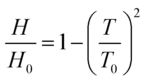 | (1) |
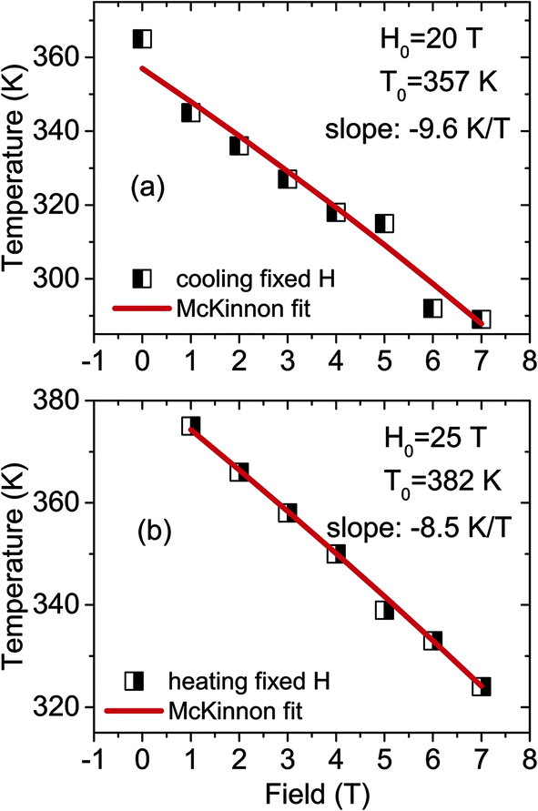 | ||
| Fig. 3 T–H phase diagram as determined from the temperature hysteresis loops in fixed magnetic fields for (a) cooling and (b) heating. | ||
In-plane magnetic field hysteresis loops were measured at different temperatures for the cooling and heating cycles and are shown in Fig. 4(a and d). The measurements were done on cooling (heating) from 400 K (from 100 K) in Ha = 0 T. Before each measurement, we demagnetized the sample at a measuring temperature and then measured while sweeping the magnetic field from 0 T to +7 T and finally completing a cycle between +7 T to −7 T. One can see that, unlike epitaxial films on Al2O3,16 the sample is not in the AF phase at zero field during the cooling process. Spontaneous magnetization develops with field reduction. However, during the heating process, it remains in the AF phase at Ha = 0 T. The rate of FM and AF nucleation and propagation can be seen in the plots Fig. 4(b, c, e and f) during cooling and heating, respectively. A similar FWHM of 0.02 T is observed in all cases, indicating similar transition rates from the FM-to-AF and AF-to-FM phases. Another notable aspect is the order of magnitude reduction in the saturation fields (0.01 T) as compared to epitaxial ones on Al2O3.
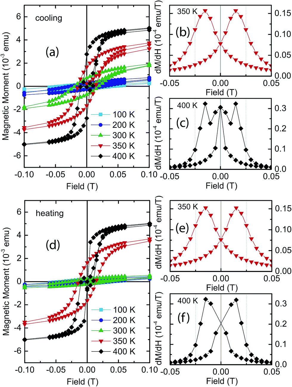 | ||
| Fig. 4 Magnetization versus field measurements and domain nucleation and propagation dM/dH. Field hysteresis loops measured at 100 K, 200 K, 300 K, 350 K and 400 K during (a) cooling and (d) heating procedures. Rate of FM and AF domain nucleation and propagation for (b and c) cooling and (e and f) for heating at two different temperatures T = 350 K and 400 K. | ||
Polarized neutron reflectivity (PNR)
Fig. 5(a and b) shows the polarized neutron intensity profiles along Qz and their fits after cooling the sample from 400 K in a field of Ha = 1 T and measuring at 1 T at 400 K and 50 K. The sample is expected to be ferromagnetic at 400 K and antiferromagnetic at 50 K. The fits were done using a simple model of block-potentials. The parameters that were used for fitting are the individual layer thicknesses, and the nuclear and magnetic SLDs of the individual layers. The error in the thickness of the layers is ±0.2 nm, while that for the nuclear and magnetic scattering length densities ρn and ρm values are ±0.1 × 10⁻⁶ Å−2 and ±0.05 × 10⁻⁶ Å−2, respectively. The interface roughness is ≃0.5 ± 0.5 nm. The magnetic scattering length densities of the top-interface and substrate-interface layers were fitted independently from the rest. The substrate ρn value at 4.5 × 10⁻⁶ Å−2, was found to be close to the theoretical SLD value of amorphous alumina (4.3 × 10⁻⁶ Å−2) and in agreement with our X-ray SLD value. | ||
| Fig. 5 PNR measurements. Specular neutron reflectivity patterns (solid symbols) along with their best fits (open symbols) as a function of Qz for the NSF [R+ (black) and R− (red)] channels, up and down, measured at Ha = 1 T and at (a) 400 K and (b) 50 K. The nuclear (ρn) and magnetic (ρm) SLDs versus the thickness of the sample are also shown inset. | ||
PNR data at 400 K
The PNR data measured at 400 K (Fig. 5(a)) show a large splitting of the R+ and R− profiles, a signature of net magnetization within the sample. The nuclear SLD ρn = 5.5 × 10⁻⁶ Å−2 is similar to the expected value (ρn = 5.7 × 10⁻⁶ Å−2) in epitaxial films.6 Interestingly, the SLD values at the bottom and at the top interfaces are distinctly different in our film. Note that the ρn value at the top-interface (ρn(top) = 7.4 × 10⁻⁶ Å−2) is reasonably close to the theoretical value (ρn(Fe) = 8.0 × 10⁻⁶ Å−2) for Fe, which strongly suggests Fe segregation which is extended to within 10 nm from the top. The substrate-interface, within 2.5 nm from the bottom, has ρn(bottom) = 3.8 × 10⁻⁶ Å−2, suggesting a Rh rich interface layer which is similar to the theoretical value for Rh (ρn(Rh) = 4.3 × 10⁻⁶ Å−2).The magnetic SLD within the film is ρm = 2.22 × 10⁻⁶ Å−2, which is equivalent to 1.11 μB per atom of FeRh. The magnetic moment within the polycrystalline film is much lower as compared to that in an epitaxial film (1.56 μB per atom of FeRh) and also to that in the bulk (2.0 μB per atom of FeRh).6 Overall, the smaller magnetic moment in our polycrystalline film may be due to a slight imbalance in the 50–50 FeRh composition with a richness of Rh.
Within 10 nm from the top-interface, ρm(top) = 0.77 × 10⁻⁶ Å−2, which is drastically reduced (≈0.39 μB per atom of FeRh) from the rest of the film. The reduction of moment at the top is also drastic as compared to that reported in the epitaxial film (≈1.32 μB per atom of FeRh).6 Within around 2.5 nm of the substrate-interface at the bottom, we find ρm(bottom) = 2.13 × 10⁻⁶ Å−2 (≈1.07 μB per atom of FeRh). However, the moment value near the substrate-interface in the polycrystalline film is higher than the value reported (0.08 μB per atom of FeRh) in the epitaxial film. Thus we can infer that at the substrate-interface, we can have a Rh enrichment which is higher than within the film.
PNR data at 50 K
The PNR data measured at 50 K in Fig. 5(b) show a small splitting of the R++ and R−− profiles, a signature of reduced net magnetization within the sample. The magnetic moment at the substrate-interface (≈1.18 μB per atom of FeRh), and at the top-interface remain similar (0.31 μB per atom of FeRh) to that at 400 K. The inner FeRh layer is completely antiferromagnetic. One may recall the non-vanishing magnetic moment below TFM–AF, as observed in the SQUID data (Fig. 2(a and b)). The persistent moment at 50 K can therefore be explained as being mostly reminiscent of the Fe rich top-interface and Rh rich substrate-interface layers at 400 K. The temperature dependence of the magnetization can be related to the magnetic phase diagram of FeRh alloys.Model simulations
In order to justify the variations in ρm with thickness, we present model simulations considering (a) a higher ρm value at the top-interface as compared to the rest of the layer and (b) a constant average value of ρm = 1 × 10⁻⁶ Å−2 for the data at 400 K. The simulated data are shown in Fig. 6(a and b). It is quite obvious that such scenarios can be ruled out. Similarly, for the 50 K data, we again present model simulations considering (a) a higher ρm value at the top-interface with no magnetization for the rest of the layer and (b) a constant average value of ρm = 0.6 × 10⁻⁶ Å−2. The simulated data are shown in Fig. 6(c and d) confirming that such models fail to match the data.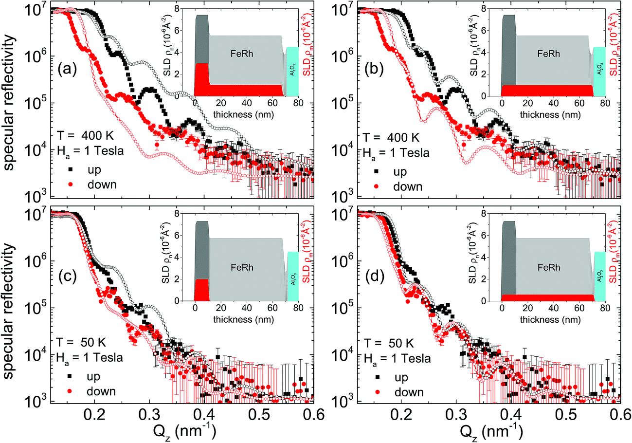 | ||
| Fig. 6 PNR measurements. Specular neutron reflectivity patterns (solid symbols) along with model simulations (open symbols) as a function of Qz for the NSF [R+ (black) and R− (red)] channels, up and down, measured at Ha = 1 T and at (a and b) 400 K and (c and d) 50 K. The nuclear (ρn) and magnetic (ρm) SLDs versus the thickness of the sample are also shown inset. We also show the model simulations considering two different models each for 400 K and 50 K with different ρm values. The mismatch with the data indicates the invalidity of the model in each case. | ||
Disordered phases
Fig. 7 shows the phase diagram of bulk FexRh100−x alloys.18 It is well known that in the range of 0–20 atomic percent (at%) of Rh, the alloy is in a chemically disordered bcc structure (A2). Thus the Rh rich bottom-interface shows some low magnetism. The long-range magnetic order of A2-FeRh arises from the dominating short-range FM exchange interactions between Fe–Fe and Fe–Rh pairs over the competing AF Fe–Fe interactions at larger separations.19,20 | ||
| Fig. 7 FeRh phase diagram. Bulk magnetic FexRh100−x phase diagram adapted from ref. 18. Metamagnetic transitions in bulk B2 FeRh are expected from the AF to the FM state at 370 K and to the PM state at 655 K. The green arrows indicate the 50–50 B2 ordered phase, being magnetic and paramagnetic. Below 10% of Rh, it is in a disordered bcc phase (A2) and above 75% of Rh it is in a disordered fcc (A1) phase. Schematic diagrams of the crystal structures for A2, B2 and A1 are also shown. | ||
When the system is in between 20 and 50 at% of Rh, it goes into a chemically ordered bcc structure (B2). Then with x < 50, i.e. when Rh is more than around 50 at%, it has a fcc structure and is not magnetic. Using Mössbauer spectroscopy, Filoti et al.21 studied magnetism in FexRh100−x bulk alloys at different temperatures, where x = 65, 50 and 26. A transition from the paramagnetic (PM) to FM phase between 375–525 K for x = 65 was demonstrated from the evolution of a sextet. It was shown that the bcc disordered phase A2 contains about 16% of the paramagnetic phase. Therefore, the loss of magnetization at the top-interface as compared to the inner portion of our sample, which is associated with Fe segregation, is caused by a disordered bcc FM phase or a near-surface/interfacial ferromagnetism in the ordered FeRh thin films.
Summary
A polycrystalline FeRh film on Al2O3 (0001) with predominant B2-order has been investigated. We found TAF–FM = 346 K (in 1 T), which can be shifted by a magnetic field to 288 K (in 7 T). The rates of transitions with field (dT/dH = −8.5 K T−1 for heating and dT/dH = −9.6 K T−1 for cooling) are similar to those in epitaxial films. We find a significant difference in the rate of domain nucleation and propagation with temperature (dM/dT) during the cooling and heating procedures. Using PNR, we show that the FeRh film is not homogeneous throughout the depth of the film. Evidence of Fe segregation at the surface of the film extended to within a few nanometers from the top-interface and Rh richness at the substrate-interface was confirmed. Overall, differences to the epitaxial film can be ascribed to the ordered and disordered polycrystallinity of the film. The inhomogeneous film changes from a disordered bcc (A2) structure at the surface to an ordered bcc (B2) structure within the film and then to a disordered fcc phase (A1) at the very bottom. We expect that, with improved growth conditions, it would be possible to grow simpler and cost effective polycrystalline FeRh films possessing similar characteristics as epitaxial ones.Conflicts of interest
The authors declare no competing financial interests.Acknowledgements
V. S., R. R., M. G., S. A. and A. T. prepared the sample. J. Y. and M. H. did the magnetization measurements. R. R., M. G. and J. S. did the PNR measurements. A. P. analyzed the data, coordinated the work, and wrote the manuscript. We would like to thank M. Opel for some of the SQUID measurements and N. Paul for the X-ray measurements. We are also thankful to E. Hueger for the SIMS measurements. The work is partially based upon the experiments performed on AMOR at the Swiss spallation neutron source SINQ, Paul Scherrer Institute in Switzerland. This work was supported by the German Research Foundation (DFG) and the Technische Universität München within the Open Access Publishing Funding Programme.References
- M. Fallot and R. Horcart, Rev. Sci., 1939, 77, 498 Search PubMed.
- F. de Bergevin and L. Muldawer, Comptes Rendus de l’Académie des Sciences, 1961, 252, 1347 Search PubMed.
- P. Kushwaha, A. Lakhani, R. Rawat and P. Chaddah, Phys. Rev. B: Condens. Matter Mater. Phys., 2009, 80, 174413 CrossRef.
- N. Fujita, S. Kosugi, Y. Saitoh, Y. Kaneta, K. Kume, T. Batchuluun, N. Ishikawa, T. Matsui and A. Iwase, J. Appl. Phys., 2010, 107, 09E302 CrossRef.
- K. Kang, A. R. Moodenbaugh and L. H. Lewis, Appl. Phys. Lett., 2007, 90, 153112 CrossRef.
- R. Fan, C. J. Kinane, T. R. Charlton, R. Dorner, M. Ali, M. A. de Vries, R. M. D. Brydson, C. H. Marrows, B. J. Hickey, D. A. Arena, B. K. Tanner, G. Nisbet and S. Langridge, Phys. Rev. B: Condens. Matter Mater. Phys., 2010, 82, 184418 CrossRef.
- R. O. Cherifi, V. Ivanovskaya, L. C. Phillips, A. Zobelli, I. C. Infante, E. Jacquet, V. Garcia, S. Fusil, P. R. Briddon, N. Guiblin, A. Mougin, A. A. Unal, F. Kronast, S. Valencia, B. Dkhil, A. Barthelemy and M. Bibes, Nat. Mater., 2014, 13, 345 CrossRef CAS PubMed.
- S. Yamada, K. Tanikawa, J. Hirayama, T. Kanashima, T. Taniyama and K. Hamaya, Phys. Rev. B: Condens. Matter Mater. Phys., 2015, 92, 094416 CrossRef.
- M. Takahashi and R. Oshima, J. Phys. IV, 1995, 05, C8–C491 CrossRef.
- R. Witte, R. Kruk, M. E. Gruner, R. A. Brand, D. Wang, S. Schlabach, A. Beck, V. Provenzano, R. Pentcheva, H. Wende and H. Hahn, Phys. Rev. B, 2016, 93, 104416 CrossRef.
- J. Stahn and A. Glavic, Nucl. Instrum. Methods Phys. Res., Sect. A, 2016, 821, 44 CrossRef CAS.
- J. Jutimoosik, R. Yimnirun, J. Stahn, A. Setzer, P. Esquinazi and A. Paul, Phys. Rev. B: Condens. Matter Mater. Phys., 2015, 91, 224428 CrossRef.
- S. Fust, S. Mukherjee, N. Paul, J. Stahn, W. Kreuzpaintner, P. Böni and A. Paul, Sci. Rep., 2016, 6, 33986 CrossRef CAS PubMed.
- A. Paul, Sci. Rep., 2016, 6, 19315 CrossRef CAS PubMed.
- L. G. Paratt, Phys. Rev., 1954, 95, 359 CrossRef.
- S. Maat, J.-U. Thiele and E. E. Fullerton, Phys. Rev. B: Condens. Matter Mater. Phys., 2005, 72, 214432 CrossRef.
- J. B. McKinnon, D. Melville and E. W. Lee, J. Phys. C: Solid State Phys., 1970, 1, S46 CrossRef.
- V. Dupuis, A. Robert, A. Hillion, G. Khadra, N. Blanc, D. L. Roy, F. Tournus, C. Albin, O. Boisron and A. Tamion, Beilstein J. Nanotechnol., 2016, 7, 1850 CrossRef CAS PubMed.
- J. Kudrnovský, V. Drchal and I. Turek, Phys. Rev. B: Condens. Matter Mater. Phys., 2015, 91, 014435 CrossRef.
- I. Ohnuma, T. Gendo, R. Kainuma, G. Inden and K. Ishida, ISIJ Int., 2009, 49, 1212 CrossRef CAS.
- G. Filoti, V. Kuncsea, E. Navarro, A. Hernando and M. Rosenberg, J. Alloys Compd., 1998, 278, 60 CrossRef CAS.
| This journal is © The Royal Society of Chemistry 2017 |