
 Open Access Article
 This Open Access Article is licensed under a
 Creative Commons Attribution 3.0 Unported Licence
Improvement of performance of a ductile/brittle polymer system by graphite nanoplatelets: effect of component coupling
Ivan Kelnar *,
Jaroslav Kratochvíl,
Ludmila Kaprálková,
Martina Nevoralová,
Miroslav Janata,
Ivan Fortelný,
Alexander Zhigunov and
Jiří Dybal
*,
Jaroslav Kratochvíl,
Ludmila Kaprálková,
Martina Nevoralová,
Miroslav Janata,
Ivan Fortelný,
Alexander Zhigunov and
Jiří Dybal
Institute of Macromolecular Chemistry, Czech Academy of Science, Heyrovského nám. 2, 162 06 Prague, Czech Republic. E-mail: kelnar@imc.cas.cz
First published on 27th July 2017
Abstract
Addition of a high-modulus polymer to a pseudo-ductile matrix may lead to increased strength, stiffness and toughness. This can be achieved by plastic deformation of a well-dispersed phase with higher modulus and lower Poisson's ratio compared with the matrix. Recently, this system has also been successfully modified by organophilized montmorillonite. In this work, a reactively compatibilized PA6/PS system is upgraded using modified graphite nanoplatelets (GNP) in combination with their simultaneous coupling to polymer components. The best balanced mechanical properties have been obtained in the case of the combination of amine-modified GNP with a styrene maleic-anhydride copolymer. Here, coupling of both polymer phases with GNP could take place. Structure of the in situ formed adduct can be controlled by component ratio and mixing protocols. The complex effect of such modified GNP on the system behaviour, including favourable change of components parameters and modification of the interface, is discussed.
Introduction
Improvement of toughness without concurrent deterioration of other parameters, i.e. preparation of polymer systems with well-balanced properties, is a constant challenge.1 Recently, simultaneously enhanced strength, stiffness and toughness were successfully achieved by modification of elastomer-toughened systems with nanofillers.2–6 An example is impact-modified PA6 (ref. 5) and PET6 with a favourable combination of reinforcement and structure-directing ability of organophilized montmorillonite (oMMT).A moderate increase in impact strength of ductile polymers, like PA6 or PC, can also be achieved by addition of rigid, usually brittle polymers, such as PS or SAN.7–9 In the case of sufficiently small particle sizes and good interfacial adhesion, the dispersed polymer may undergo plastic deformation instead of brittle fracture – the cold-drawing concept. This is possible due to the fact that loading of a system containing inclusions of high modulus and Poisson's ratio lower than that of a matrix may generate hydrostatic stress onto the inclusions. Sufficiently high hydrostatic pressure may lead to yielding because ductile–brittle transition (plastic deformation) of brittle polymers can be supported by increased pressure, as shown experimentally by Baer.10
In the system PA6/styrene maleic-anhydride copolymer (SMA) with parameters of the minority phase changed by alkyl-modification, effect of components moduli and Poisson's ratios was highlighted.8 The cold drawing of rigid particles was also achieved by their combination with elastomeric inclusions leading to favourable interactions of dissimilar (compression vs. elongational) stress fields.11 This system was successfully modified by clay.12 Relatively good efficiency of layered silicates in the ductile/brittle system was demonstrated in our previous study of PA6/PS.13 The best properties were found with the clay localized at the interface.
At the same time, the smaller range of organo-modifications and experimentally difficult coupling with polymer chains are a limiting factor of oMMT use.14,15 In this respect, carbon nanoplatelets, like graphene oxide, are a more promising structure-directing/reinforcing modifier, as shown in increasing number of works.16–23 Some commercial graphite nanoplatelets (GNP)24 show similar affinity to polymers and contain similar reactive groups for modifications.
In this work, we have focused on the effect of GNP, including their coupling with polymer components, on structure and properties of the ductile/brittle systems PA6/PS and PA6/(PS + SMA). The role of SMA is both reactive compatibilization9 and coupling with aminated GNP to form polymer-modified nanofiller.
Experimental
Materials
Polyamide 6 (PA6) Ultramid B5 with Mn 42![[thin space (1/6-em)]](https://www.rsc.org/images/entities/char_2009.gif) 000 (BASF); polystyrene (PS) homopolymer, Krasten 171 (Synthos); styrene-maleic anhydride (8%) copolymer (SMA) Dylark 232 (Nova Chemicals).
000 (BASF); polystyrene (PS) homopolymer, Krasten 171 (Synthos); styrene-maleic anhydride (8%) copolymer (SMA) Dylark 232 (Nova Chemicals).
Graphite nanoplatelets (GNP), grade C with oxygen content 6–8%, typical particle thickness of few nanometers and diameter of less than 2 μm, 750 m2 g−1 surface area (XG Sciences, Inc.)
Modification GNP with ethylenediamine (GNPA)
(1) The mixture of GNP (10 g) and ethylenediamine (5 mL) in ethanol (100 mL) was refluxed for 5 hours and then stirred at room temperature for 19 hours. The crude reaction mixture was centrifuged and washed several times with ethanol which was finally replaced with tetrahydrofuran (THF). Elemental analysis of GNPA found 2.8% N content.(2) The mixture of GNP (10 g) and thionyl chloride (70 mL) was refluxed at ca. 75 °C for 5 hours and then stirred at room temperature for 19 hours. The excess of SOCl2 was removed by simple atmospheric distillation followed by azeotropic distillation with dry toluene (3 × 50 mL of toluene). Subsequently, triethylamine (0.5 mL) and ethylenediamine (10 mL) were added. The reaction mixture in toluene was refluxed for 4 hours and then stirred at room temperature for 18 hours. All distillations were performed in an apparatus equipped with an anhydrous calcium chloride guard tube. Finally, the crude reaction mixture was filtered on a sintered glass filter and the obtained product was dried in vacuum. The degree of the ethylenediamine-modification (Fig. 1) was substantially higher, elemental analysis found 8% N content.
 | ||
| Fig. 1 Modification of GNP with ethylenediamine. | ||
Nanocomposite preparation
Prior to mixing, PA6 was dried in a vacuum oven at 85 °C for 12 h. The blends and corresponding nanocomposites were prepared by mixing the components in the W50EH chamber of a Brabender Plasti-Corder at 250 °C and 45 rpm for 10 min. The mixture removed from the chamber was compression-moulded at 250 °C to form 1 mm thick plates. Strips cut from the plates were used for preparation of dog-bone specimens (gauge length 40 mm) in a laboratory micro-injection moulding machine (DSM). The barrel and mould temperatures were 265 °C and 80 °C, respectively.The PA6/PS/GNP system was prepared by simultaneous melt mixing of all components. SMA or PS/SMA were mixed with GNP in THF at ambient temperature to form adducts. After the reaction (usually 2 hours), THF was evaporated at ambient temperature and the adduct was dried in a vacuum oven at 60 °C for 8 h. In most cases, GNPA containing 2.8% N was used. Analogous mixtures with GNP were prepared in the same way. All SMA-based systems were prepared by subsequent mixing with PA6.
Evaluation of mechanical properties
Tensile tests were carried out using an Instron 5800 apparatus at 22 °C and crosshead speed of 20 mm min−1. At least 8 specimens were tested for each sample. Young's modulus (E), maximum stress (σm) and elongation at break (εb) were evaluated. Corresponding variation coefficients did not exceed 10%, 2% and 20%, respectively.Tensile impact strength, at, was measured with one-side notched specimens, using a Zwick hammer with energy of 4 J (variation coefficient 10–15%). The reported values are averages of 12 individual measurements.
Dynamic mechanical analysis (DMA) was performed in the single-cantilever mode using a DMA DX04T apparatus at 1 Hz and heating rate 1 °C min−1 in the range from −120 to 250 °C.
ATR FTIR
Fourier-transform infrared (FTIR) spectra were recorded with a Thermo Nicolet NEXUS 870 FTIR spectrometer using a DTGS TEC detector. The powder samples were mixed with potassium bromide and pressed into pellets. The FTIR spectra were obtained in the transmission mode coadding 64 scans at a resolution of 2 cm−1. The distortion of the band shapes due to high reflectance of the samples was corrected by the Kramers–Kronig relation using OMNIC software. An absorption subtraction was applied to remove spectral features of the KBr pellet including absorbed water and water vapour.The model quantum chemical calculations were carried out at the density functional theory (DFT) using the B3LYP functional and the 6-311+G(2d,p) basis set with the Gaussian 09 program package.25 In order to verify the reliability of the DFT results, the stable structures were then reoptimized at the Møller–Plesset (MP2) level of theory (MP2/6-31+G(d)). Vibrational frequencies of the normal modes were calculated at the B3LYP/6-311+G(2d,p) level and the obtained values were scaled by the scaling factor of 0.9692.26
X-ray diffraction
XRD experiments were performed using a pinhole camera (modified Molecular Metrology System, Rigaku, Japan) attached to a microfocused X-ray beam generator (Rigaku MicroMax 003) operating at 50 kV and 0.6 mA (30 W). The camera was equipped with a vacuum version of Pilatus 300 K detector. Experimental setup covers the q range of 0.3–3.4 Ǻ−1. Scattering vector, q, is defined as: q = (4π/λ)sinθ, where λ is the wavelength and 2θ is the scattering angle. Exposure time was 30 minutes. Data were normalized on sample thickness and transmission. Primary beam position and sample-to-detector distance were calibrated using Si powder sample. Software Fityk version 0.9.8 (ref. 27) was used for peak decomposition. Degree of crystallinity was calculated as ratio of crystalline peaks area to whole area, including amorphous halo.
Differential scanning calorimetry
The DSC analysis was carried out using a Perkin-Elmer 8500 DSC apparatus. Cyclohexane and indium were used for calibration. The instrument was used with natural cooling and flushed with dry nitrogen as a purge gas. The samples were heated from 50 to 280 °C at the rate of 10 °C min−1. The value of 230 J g−1 was used as the heat of melting of 100% crystalline PA6 in calculating its crystallinity.Morphological observations
Scanning electron micrographs were obtained using a Vega (Tescan) microscope. The phase structure was observed on cryo-fractured samples (liquid nitrogen) etched with toluene for 30 min. The size of dispersed particles was investigated using a MINI MOP image analyzer (Kontron Co., Germany).In the case of transmission electron microscopy (TEM) observations, ultrathin (60 nm) sections were prepared under liquid nitrogen using an Ultracut UCT (Leica) ultramicrotome. The presented images are representative samples selected from dozens of observations.
Results and discussion
Effect of GNP on structure
Fig. 2 shows the emulsification curve indicating great effect of low GNP content (up to 1 phr) on refinement of the PS inclusions in the PA6/PS 90/10 system, see Fig. 3a and b. The compatibilizing effect of GNP is comparable with that of nanoclay5,28 or reactive compatibilization taking place in the PA6/(SMA/PS 8/2) blend. The fact that particle size decreases in spite of marked presence of GNP inside the PS phase (Fig. 4a), which may hinder its break-up, is ascribed to the “cutting effect” of GNP stacks inside PS on their break-up by shear forces.29 At the same time, significant polydispersity was found, especially at lower contents of GNP. Such phase behaviour is typical of the PA6/PS blend.30 In the case of reactive compatibilization (using SMA/PS 8/2), the addition of GNP has negligible effect on particle size due to obvious dominancy of hindering of reactive compatibilization (PA-SMA copolymer formation)9 by GNP over possible compatibilization effect. This is confirmed by certain decrease in size at 0.5 phr GNP content only (not shown). The difference between GNP and aminated GNP (GNPA) is negligible in contrast to PA/SMA (see below).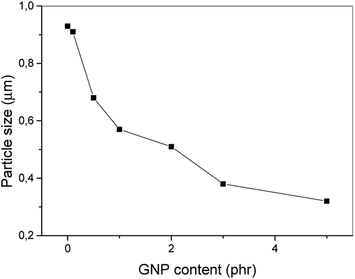 | ||
| Fig. 2 Effect of GNP on PS particle size of PA6/PS 90/10 system. | ||
 | ||
| Fig. 3 SEM images of (a) PA6/PS 90/10, (b) PA6/PS/GNP 90/10/5 (c) PA/SMA/GNP 90/10/1 systems. The examples of etched particles are indicated by white circles. | ||
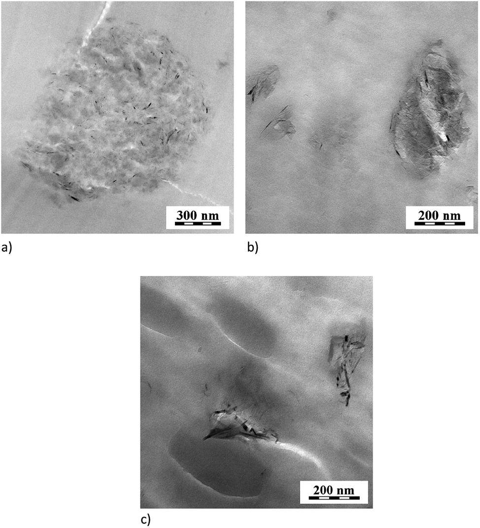 | ||
| Fig. 4 TEM images (a) PA6/PS/GNP 90/10/1, (b) PA6/SMA/GNPA 90/10/2, (c) PA6/(PS/SMA8/2)/GNPA 90/10/2. | ||
In the PA/SMA system, fine SMA size of ∼50 nm is a consequence of efficient reactive compatibilization. The unclear boundary of etched particles can be attributed to presence of reactively formed PA/SMA copolymer at the interface.9 In this reactive system, particle size (Fig. 3c) only slightly increases (to ∼60 nm) with GNP addition. Due to higher extent of the PA-SMA copolymer formation, the NF-hindering is more pronounced.4 In the case of GNPA, the increase is more marked (to ∼100 nm) due to reduced reactivity of SMA caused by formation of the adduct with GNPA. This indicates that the in situ formed PA/SMA copolymer is the best compatibilizer in this system in agreement with other NF-modified reactively compatibilized systems.4,9
TEM image (Fig. 4b) indicates expected dominant localization of GNPA in dispersed SMA and at the interface.31 Presence of unmodified GNP in the PS inclusions was also found in the PA/PS system. This can be explained by low and similar interfacial energies of PA6/GNP and PS/GNP, and wetting coefficient between −1 and 1. This indicates GNP localization in both components, more probably in PA6 (ref. 24) due to lower interfacial energy. The marked GNP presence in PS is a consequence of its penetration into this first-melting polymer. The subsequent migration of large GNP across the interface is relatively difficult.32 Consequently, the GNP/PA6 reaction24 that would support GNP localization in PA6 is suppressed.
ATR FTIR
In GNPA prepared by the ethylenediamine-modification, the content of imide groups in the SMA/GNPA adduct was mostly below the resolution limit of FTIR. This was the case of GNPA with lower degree of the amine-modification (using epoxy-functionality only, see Fig. 1). Here, the coupling was confirmed by significant presence of non-extractable SMA after 8 h extraction in a Soxhlet apparatus (not shown). The imide group was detected only in GNPA with higher degree of amination (Fig. 5).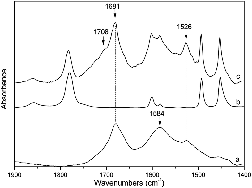 | ||
| Fig. 5 FTIR spectra of (a) GNPA, (b) SMA and (c) extracted SMA + GNPA, together with relevant band frequencies (in cm−1). | ||
In comparison with SMA, several new bands appear in the FTIR spectrum of the SMA/GNPA adduct (Fig. 5). The bands at 1681 and 1526 cm−1 are assigned to the amide I and amide II vibrations of the amide group, which is supported by the DFT model calculations (Fig. 6). These two bands were also observed in the spectrum of GNPA (Fig. 5); the band at 1584 cm−1 is assigned to the CC stretching vibration of the graphene sheet, in accordance with the model calculations (Fig. 6). The band at 1708 cm−1 corresponds to the out-of-phase C![[double bond, length as m-dash]](https://www.rsc.org/images/entities/char_e001.gif) O stretching vibrations of the maleimide group (Fig. 5). Appearance of this band is in agreement with the concept of transformation of some of maleic anhydride groups into maleimide. This is also supported by the observed decrease (∼25%) of the relative intensity of the band at 1780 cm−1 attributed to the out-of-phase CO stretching vibrations of the maleic anhydride groups. Application of these adducts has shown that higher degree of reaction was unfavourable – it did not lead to better properties.
O stretching vibrations of the maleimide group (Fig. 5). Appearance of this band is in agreement with the concept of transformation of some of maleic anhydride groups into maleimide. This is also supported by the observed decrease (∼25%) of the relative intensity of the band at 1780 cm−1 attributed to the out-of-phase CO stretching vibrations of the maleic anhydride groups. Application of these adducts has shown that higher degree of reaction was unfavourable – it did not lead to better properties.
 | ||
| Fig. 6 DFT (B3LYP/6-311+G(2d,p)) optimized structure of the segment SMA + GNPA together with calculated frequencies of the indicated vibrational modes (in cm−1). | ||
The extent of reaction between the components and thus structure of the formed adducts is significantly influenced by the mixing protocol, as indirectly indicated by its crucial effect on DMA and rheological behaviour (see below). The difference between PA6/SMA/GNPA and the analogous system containing SMA diluted with PS (2/8) is also obvious from TEM (Fig. 4b and c)
Finally, the SMA/GNPA adduct can react with PA6 or formation of GNP with attached PA and SMA can be expected in the case of simultaneous mixing of all components. However, due to low conversion, these “compounds” could not be distinguished.
Dynamic mechanical analysis
The temperature dependences of loss modulus of the PA6/PS system in Fig. 7 indicate immobilization of polymer chains by GNP leading to increased Tg of PS and PA6 by ∼1 °C and ∼3 °C, respectively. This approximately corresponds to the effect of GNP on Tg in PA6/GNP and PS/GNP, which confirms presence of GNP in both phases. In the blend, Tg of PA6 is higher and that of PS is lower than that in the corresponding single nanocomposites. This indicates a slight compatibilization effect of GNP (leading to merging of both Tg). | ||
| Fig. 7 Temperature dependence of loss modulus of PA6/PS 90/10 in dependence on GNP content. | ||
In the PA6/SMA/GNPA system (Fig. 8a), DMA confirms different structures of the adducts in dependence on GNPA content. Significant approach of components Tg at 2% GNPA is obviously a consequence of higher content of SMA and SMA-g-PA6 coupled with GNPA. In the case of GNP (Fig. 8b), the negligible effect of GNP content corresponds to expected disturbing of reaction between the polymer components at higher GNP content.
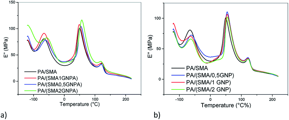 | ||
| Fig. 8 Temperature dependence of loss modulus of PA6/SMA 90/10 in dependence on (a) GNPA content, (b) GNP content. | ||
If SMA is replaced by the PS/SMA 8:2 combination, the effect of GNPA on Tg is comparable (not shown). At the same time, certain differences between the systems prepared with different mixing protocols (Fig. 9) indicate important role of this aspect on formation and structure of the adducts.
 | ||
| Fig. 9 Temperature dependence of loss modulus in PA6/PS/SMA 90/8/2 in dependence on mixing protocol (sol = PS/SMA/GNPA pre-blend prepared in THF solution, melt = one-step melt mixing of all components). | ||
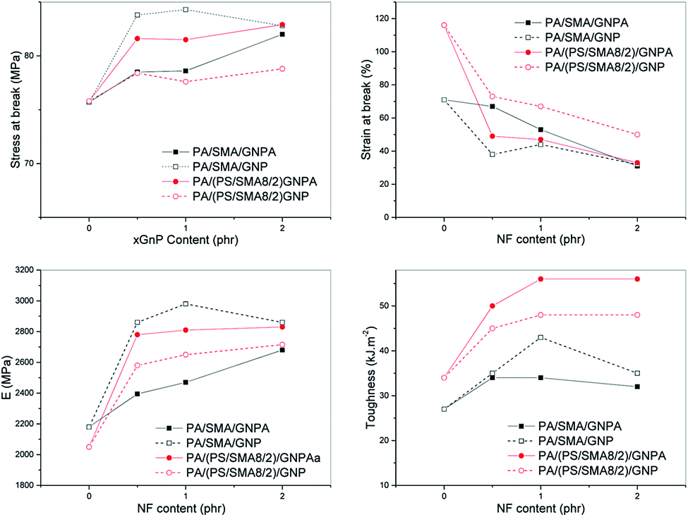
Effect of GNP on mechanical properties
In the system with the PA/PS 90/10 matrix (Fig. 10a and b), the reinforcing effect of GNP is different in comparison with oMMT.12 This consists in more marked increase of mechanical parameters, especially modulus and tensile strength, at low (<1%) GNP content followed by much less steep growth at higher contents. Similar effect on modulus was found for the PA6 matrix containing GNP (Fig. 10b) and analogous “rougher” GNP (500 m2 g−1).24 Due to no indication of GNP stacking at its higher contents (see absence of peak at 2θ = 26.13° in Fig. 11), other effects must be considered. Partial explanation can be seen in small decrease of crystallinity at higher GNP content (Fig. 12). We tentatively consider negative effect of higher portion of PA6 chains linked to GNP at its higher content.24 This may lead to lower content of PA6 spherulites at the interphase of GNP.33 The Finite Element Analysis of this phenomenon is in progress.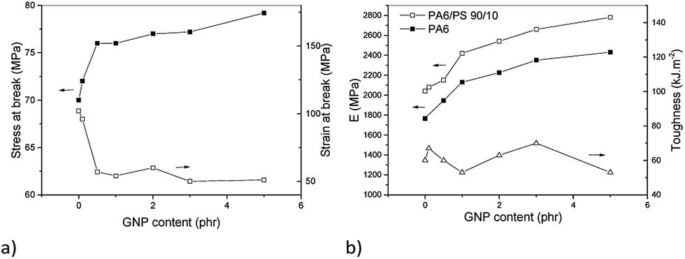 | ||
| Fig. 10 Effect of GNP on mechanical behaviour of PA6/PS 90/10 system (a) stress at break and strain at break, (b) modulus and toughness. | ||
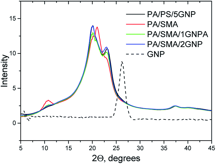 | ||
| Fig. 11 XRD spectra of PA6/PS and PA6/SMA (90/10) with GNP. | ||
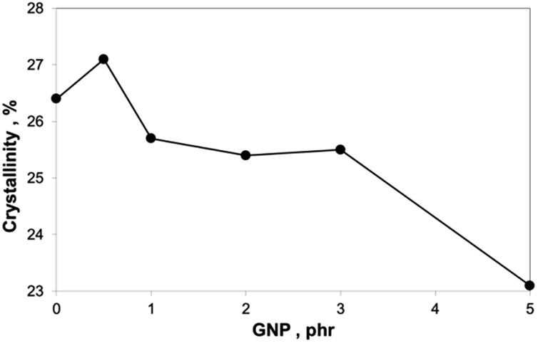 | ||
| Fig. 12 Dependence of PA6 crystallinity on filler content: PA6/PS 90/10 + GNP. | ||
An advantage is that no negative impact on toughness occurred in the whole range of GNP content. The fact that GNP does not disturb plastic deformation of the PS phase is confirmed by presence of “fibrous” elongated PS domains (Fig. 13a). As a result, a material with well-balanced properties can be prepared. Analogously to oMMT-modified systems,12 these balanced mechanical properties were achieved with the PA6/PS 90/10 composition only, whereas lowering of practically all parameters occurred with the 80/20 ratio (not shown). The fact that even certain maximum in toughness occurs at relatively high content of GNP probably corresponds to the mentioned lower reinforcing effect. Changed parameters of the interface may also be important.33,34
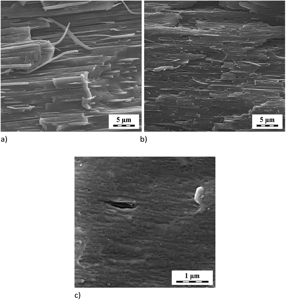 | ||
| Fig. 13 SEM image of elongated neck of (a) PA6/PS/GNP 90/10/1, (b) PA6/(PS/SMA)/GNPA 90/(8/2)/1, (c) PA6/SMA/GNP 90/10/1. | ||
If PS is replaced by SMA, either fully or partially (PS/SMA 8/2), more aspects should be considered. These include the above mentioned reactive compatibilization and coupling reactions of GNPA. At the same time, differences in PA6 crystallinity are relatively low (see below).
Fig. 14 shows best strength and stiffness for PA/SMA/GNP; however, these parameters are significantly lower for the analogous GNPA-system. Elongation and toughness are slightly better in the GNPA-system, which corresponds to lower E. Further difference is certain minor drop of E and strength for 2 phr GNP content in comparison with their monotonous increase with GNPA content.
 | ||
| Fig. 14 Effect of GNP on mechanical parameters of PA6/PS 90/10 system. | ||
Quite opposite trends were found for the PA6/(PS/SMA8/2) systems. Here, much higher E, strength and toughness occur in PA/(PS/SMA8/2)/GNPA in comparison with the analogous GNP-system. Due to the fact that E and strength of PA/(PS/SMA8/2) GNPA are practically comparable to those of PA/SMA/GNP, the former system has better balanced properties thanks to significantly higher toughness, comparable to PA/PS. This corresponds to the observed plastic deformation of the dispersed phase, apparently not disturbed by GNP (Fig. 12b).
In the case of SMA with much finer inclusions (Fig. 3), this plastic deformation was practically not observed (Fig. 13c). Due to apparent good interfacial bonding caused by the in situ formed copolymer (linking between components), the dispersed SMA particles were not well-visible because of their poor etching (see above). Therefore, at least partial plastic deformation cannot be excluded. Anyway, the results (Fig. 14) indicate that ultrafine particles with the PA/SMA copolymer-formed interphase35 are less effective in the ductile/brittle system. This is confirmed by the fact that low toughness of all PA/SMA systems occurs in spite of rather higher content of the tougher γ crystalline phase (∼15% vs. ∼11% in PA/PS) found by XRD.
Fig. 14 shows opposite effect of GNPA/SMA coupling on behaviour of the PA6/SMA and PA6 (PS/SMA8/2) systems. This rather unexpected but interesting finding consists in enhanced parameters of SMA/GNP and PS/SMA/GNPA in comparison with SMA/GNPA and PS/SMA/GNP (Fig. 14). In this respect, we can consider more favourable structure of the GNPA/SMA adduct in the (PS/SMA 8/2) system connected with lower extent of coupling. This leads to higher content of free anhydride and also to lower steric hindrance of attached GNP in the reaction with PA6. Therefore, more significant formation of the ternary adduct can be considered.
Effect of GNP and coupling on PA6 crystallinity
The results of DSC analysis (Fig. 12 and 15) indicate relatively small differences in crystallinities of PA6 in all samples studied. Certain increase in crystallinity in spite of reactive compatibilization is surprising;9 the reason seems to consist in the combined effect of SMA and low content of the nanofiller.36 Comparison of Fig. 14 and 15 indicates similar trends of dependence of E and crystallinity on GNP content. However, the fact that differences in crystallinity are few percent only implies that changes in mechanical properties are rather caused by reinforcement with GNP, structure of the formed adducts, parameters of the interphase, etc. | ||
Fig. 15 Dependence of PA6 crystallinity on filler content: —●— PA6/SMA 90/10 + GNP; ![[dash dash, graph caption]](https://www.rsc.org/images/entities/char_e091.gif) ○ PA6/SMA 90/10 + GNPA; —▲— PA6/PS/SMA 90/8/2 + GNP; △ PA6/PS/SMA 90/8/2 + GNPA. ○ PA6/SMA 90/10 + GNPA; —▲— PA6/PS/SMA 90/8/2 + GNP; △ PA6/PS/SMA 90/8/2 + GNPA. | ||
The XRD results of PA6 crystallinity (Fig. 11) correspond to DSC; the only difference is presence of low (approximately one tenth of total crystallinity) content of the γ phase indicated by peaks at 2θ = 10.63° and 2θ = 21.48° (below the resolution of DSC). The γ phase content is higher for the SMA-modified systems; in practically all cases, it decreases with GNP (GNPA) content.
Effect of GNP and components coupling on rheological behaviour
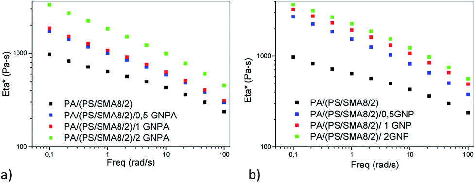
Fig. 16 shows that absolute values of complex viscosity of the PA/PS/GNP nanocomposites increase with content of GNP in the PA/PS (90/10) blend. The increase in viscosity is most pronounced at small frequencies. In accord with our previous work,24 the contribution of GNP may be enhanced by coupling between PA6 and GNP. | ||
| Fig. 16 Effect of GNP content on complex viscosity of PA6/PS 90/10 system. | ||
It follows from Fig. 16–19 that rheological behaviour of the systems with the reactive components is significantly affected by addition of GNP or GNPA. Moreover, the systems containing SMA and SMA/PS combination show different trends. As expected, coupling of the components leads to higher viscosity than that of PA6/PS-systems due to increased molecular weight. Surprisingly, increase in viscosity of the PA/SMA/GNPA nanocomposite with GNPA content is not monotonous in the region of small frequencies (Fig. 17a). Here, reactions of PA6 with the SMA/GNPA adduct (prepared prior to mixing with PA6) must be considered. The amount and architecture of the final adduct, controlled by GNPA/SMA ratio, has crucial effect on rheological behaviour as also confirmed by differences in strain hardening.
 | ||
| Fig. 17 Effect of (a) GNPA and (b) GNP content on complex viscosity of PA/SMA 90/10 system. | ||
Fig. 17b shows that viscosity of the GNP-system is higher and its dependence on nanofiller content is less marked in comparison with the system containing GNPA. In the GNP-system, reactive compatibilization (formation of the SMA/PA6 copolymer) is accompanied with both mechanical reinforcement and hindering of this reaction by GNP. Slight reduction of viscosity for 2% GNP indicates that the hindering effect dominates at higher nanofiller contents.
Lower viscosity of the PA/SMA/GNPA system seems to be a consequence of formation of the GNPA/SMA adduct at the expense of the PA/SMA copolymer.
From Fig. 18a and b, it follows that in the systems containing SMA diluted with PS, viscosity of PA6 (PS/SMA 8/2)/GNPA is higher than that of the analogous GNP-system; moreover in both cases, viscosity monotonously increases with NF content. The reason seems to be more favourable structure of the SMA/GNPA adduct with lower extent of linking between SMA and GNPA. This leads to higher content of free anhydride for subsequent reaction with PA6 and expected lower hindering effect of GNPA. This results in formation of a more bulky adduct with higher impact on viscosity.
 | ||
| Fig. 18 Effect of (a) GNPA and (b) GNP on complex viscosity of PA6/(PS/SMA 90/8/2) matrix nanocomposite. | ||
Lower viscosity of the PA6 (PS/SMA 8/2)/GNP system is probably a consequence of lower extent of reactive compatibilization. In this case, the hindering effect of GNP is less significant and reinforcing dominates.
The importance of the adduct structure follows also from Fig. 19 which compares viscosity of the PA/(PS/SMA 90/8/2)/GNPA system prepared using two mixing protocols: (i) masterbatch of SMA and GNP reacted in solution for 2 h, and PS added thereafter; (ii) all the components mixed together. The system prepared with the latter protocol shows markedly higher viscosity; this also confirms more favourable parameters of the SMA/GNPA adduct formed in presence of PS.
 | ||
| Fig. 19 Dependence of complex viscosity of PA6/PS/SMA 90/8/2 system on mixing protocol. PS/SMA/GNPA pre-blend prepared in THF solution; bracket indicates first mixing of GNPA with SMA. | ||
Finally, importance of architecture of the adducts is also indicated by differences in strain hardening. Moreover, degree of exfoliation of the nanoplatelets and their distribution between the PA6 and SMA phases also influence rheology of the system. Unfortunately, due to unknown structure of the formed adducts, unambiguous interpretation of rheological properties of these systems is difficult. The formation of these adducts is also confirmed by marked impact on all other parameters studied (see above).
Conclusions
The results indicate that the combination of a rigid polymer and GNP can improve mechanical parameters of the PA6-matrix system. The best results, i.e. higher strength, stiffness and non-reduced toughness, were achieved in the case of the amine-modified GNP in combination with PS and styrene-maleic anhydride copolymer. Here, coupling of both polymer phases with GNPA could take place. This enhances the reinforcing and structure-directing effects of the nanofiller as indicated by marked impacts on DMA and rheology. In addition to variation in component ratios, structure of the in situ formed adduct can also be tailored by mixing protocols.Formation of the ternary adduct, i.e. GNPA modified with PA/SMA copolymer, prevails over the effect of combination of reactive compatibilization of the polymer components with reinforcement by unmodified GNP.
Acknowledgements
This work was supported by Czech Science Foundation (Grant No. 16-03194S).Notes and references
- Polymer Blends, ed. D. R. Paul and C. B. Bucknall, John Wiley & Sons, New York, 2000, pp. 83–118 Search PubMed.
- W. S. Chow and Z. A. Mohd Ishak, eXPRESS Polym. Lett., 2015, 9, 211–232 CrossRef CAS.
- S. Balakrishnan, P. R. Start, D. Raghavan and S. D. Hudson, Polymer, 2005, 46, 11255–11262 CrossRef CAS.
- I. Kelnar, J. Kotek, L. Kaprálková and B. S. Munteanu, J. Appl. Polym. Sci., 2005, 96, 288–293 CrossRef CAS.
- I. Kelnar, V. Khunová, J. Kotek and L. Kaprálková, Polymer, 2007, 48, 5336–5339 CrossRef.
- I. Kelnar, V. Sukhanov, J. Rotrekl and L. Kaprálková, J. Appl. Polym. Sci., 2010, 116, 3621–3628 CAS.
- K. K. Koo, T. Inoue and K. Miyasaka, Polym. Eng. Sci., 1985, 25, 741–746 CAS.
- W. L. Nachlis, R. P. Kambour and W. J. MacKnight, Polymer, 1994, 35, 3643–3657 CrossRef CAS.
- I. Kelnar, M. Stephan, L. Jakisch and I. Fortelný, J. Appl. Polym. Sci., 1997, 66, 555–562 CrossRef CAS.
- K. Matsushige, S. V. Radcliffe and E. Baer, J. Appl. Polym. Sci., 1976, 20, 1853–1866, DOI:10.1002/app.1976.070200714.
- I. Kelnar, M. Stephan, L. Jakisch and I. Fortelný, J. Appl. Polym. Sci., 1999, 74, 1404–1411 CrossRef CAS.
- I. Kelnar, J. Rotrekl, J. Kotek, L. Kaprálková and J. Hromádková, Eur. Polym. J., 2009, 45, 2760–2766 CrossRef CAS.
- I. Kelnar, J. Rotrekl, J. Kotek and L. Kaprálková, Polym. Int., 2008, 57, 1281–1286 CrossRef CAS.
- Polymeric nanocomposites, ed. S. N. Bhattacharya, R. K. Gupta and M. R. Kamal, Hanser, Munich, 2008 Search PubMed.
- J. Zhang, E. Manias and C. A. Wilkie, J. Nanosci. Nanotechnol., 2008, 8, 1597–1615 CrossRef CAS PubMed.
- J. Ma, C. Liu, R. Li and J. Wang, J. Appl. Polym. Sci., 2012, 123, 2933–2944 CrossRef CAS.
- G. Vleminckx, S. Bose, J. Leys, J. Vermant, M. Wübbenhorst, A. A. Abdala, C. Macosko and P. Moldenaers, ACS Appl. Mater. Interfaces, 2011, 3, 3172–3180 CAS.
- Y. Cao, J. Zhang, J. Feng and P. Wu, ACS Nano, 2011, 5, 5920–5927 CrossRef CAS PubMed.
- S. Ye, Y. Cao, J. Feng and P. Wu, RSC Adv., 2013, 3, 7987–7995 RSC.
- J. J. Shao, W. Lv and Q. H. Yang, Adv. Mater., 2014, 26, 5586–5612 CrossRef CAS PubMed.
- Y. Cao, J. Feng and P. Wu, J. Mater. Chem., 2012, 22, 14997–15005 RSC.
- G. P. Kar, S. Biswas and S. Bose, Phys. Chem. Chem. Phys., 2015, 17, 1811–1821 RSC.
- P. K. S. Mural, A. Banerjee, M. S. Rana, A. Shukia, B. Padmanabhan, S. Bhadra, G. Madras and S. Bose, J. Mater. Chem., 2014, A2, 17635–17648 RSC.
- T. D. Thanh, L. Kaprálková, J. Hromádková and I. Kelnar, Eur. Polym. J., 2014, 50, 39–45 CrossRef CAS.
- M. J. Frisch, G. W. Trucks, H. B. Schlegel, G. E. Scuseria, M. A. Robb, J. R. Cheeseman, G. Scalmani, V. Barone, B. Mennucci, G. A. Petersson, H. Nakatsuji, M. Caricato, X. Li, H. P. Hratchian, A. F. Izmaylov, J. Bloino, G. Zheng, J. L. Sonnenberg, M. Hada, M. Ehara, K. Toyota, R. Fukuda, J. Hasegawa, M. Ishida, T. Nakajima, Y. Honda, O. Kitao, H. Nakai, T. Vreven, J. A. Montgomery Jr, J. E. Peralta, F. Ogliaro, M. Bearpark, J. J. Heyd, E. Brothers, K. N. Kudin, V. N. Staroverov, R. Kobayashi, J. Normand, K. Raghavachari, A. Rendell, J. C. Burant, S. S. Iyengar, J. Tomasi, M. Cossi, N. Rega, J. M. Millam, M. Klene, J. E. Knox, J. B. Cross, V. Bakken, C. Adamo, J. Jaramillo, R. Gomperts, R. E. Stratmann, O. Yazyev, A. J. Austin, R. Cammi, C. Pomelli, J. W. Ochterski, R. L. Martin, K. Morokuma, V. G. Zakrzewski, G. A. Voth, P. Salvador, J. J. Dannenberg, S. Dapprich, A. D. Daniels, Ö. Farkas, J. B. Foresman, J. V. Ortiz, J. Cioslowski and D. J. Fox, Gaussian 09, Revision D.01, Gaussian, Inc., Wallingford CT, 2013 Search PubMed.
- J. P. Merrick, D. Moran and L. Radom, J. Phys. Chem. A, 2007, 111, 11683–11700 CrossRef CAS PubMed.
- M. Wojdyr, J. Appl. Crystallogr., 2010, 43, 1126–1128 CrossRef CAS.
- J. Yang, L. Sun, S. Xiang, J. He, L. Gu and M. Zhong, J. Appl. Polym. Sci., 2008, 110, 276–282 CrossRef CAS.
- Y. Zhu, H. Ma, L. Tong, Z. Fang and J. Zhejiang, J. Zhejiang Univ., Sci., A, 2008, 9, 1614–1620 CrossRef CAS.
- I. Fortelný, M. Lapčíková, F. Lednický, Z. Starý and Z. Kruliš, Polym. Eng. Sci., 2008, 48, 466–472 Search PubMed.
- C. Lu, X. Hu, Y. He, X. Huang, J. Liu and Y. Zhang, Polym. Bull., 2012, 68, 2071–2087 CrossRef CAS.
- A. Göldel, G. R. Kasaliwal, P. Pötschke and G. Heinrich, Polymer, 2012, 53, 411–421 CrossRef.
- I. Kelnar, J. Kratochvíl, L. Kaprálková, Z. Padovec, M. Růžička, A. Zhigunov and M. Nevoralová, J. Appl. Polym. Sci., 2017, 134, 44712 CrossRef.
- I. Kelnar, L. Kaprálková, J. Kratochvíl, Z. Padovec, M. Růžička and J. Hromádková, Polym. Bull., 2016, 73, 1673–1688 CrossRef CAS.
- B. K. Kim and S. J. Park, J. Appl. Polym. Sci., 1991, 43, 357–363 CrossRef CAS.
- X. Cai and G. Wu, J. Macromol. Sci., Part B: Phys., 2014, 53, 347–357 CrossRef CAS.
| This journal is © The Royal Society of Chemistry 2017 |