
 Open Access Article
 This Open Access Article is licensed under a Creative Commons Attribution-Non Commercial 3.0 Unported Licence
A metal-free 3C-SiC/g-C3N4 composite with enhanced visible light photocatalytic activity
Hao Xua,
Zhixing Gan *b,
Weiping Zhouc,
Zuoming Dingb and
Xiaowei Zhanga
*b,
Weiping Zhouc,
Zuoming Dingb and
Xiaowei Zhanga
aFaculty of Science, Ningbo University, Ningbo 315211, China
bKey Laboratory of Optoelectronic Technology of Jiangsu Province, School of Physics and Technology, Nanjing Normal University, Nanjing 210023, China. E-mail: zxgan@njnu.edu.cn
cDepartment of Applied Physics, Nanjing University of Science and Technology, Nanjing 210094, China
First published on 16th August 2017
Abstract
Insufficient visible light absorption and fast recombination of the photogenerated electron–hole pairs have seriously hampered the photocatalytic performance of graphitic carbon nitride (g-C3N4) up to now. To break these barriers, a novel metal-free composite based on 3C-silicon carbide (3C-SiC) nanoparticles (NPs) and g-C3N4 sheets was constructed and thoroughly investigated in the research reviewed in this report. Specifically, the enhanced visible light absorption of the 3C-SiC-NP-decorated g-C3N4 composite was verified using absorption spectra, and the effective separation of photogenerated carriers by the Type-II heterostructure band alignment forming between 3C-SiC and g-C3N4 was revealed using both steady-state and time-resolved photoluminescence spectra. The enhanced photocatalytic activity of the 3C-SiC-NP-decorated g-C3N4 composite was demonstrated experimentally using the degradation of methyl orange under visible light irradiation.
1. Introduction
Graphitic carbon nitride (g-C3N4), a metal-free n-type polymer semiconductor, has attracted enormous research interest because of its photocatalytic activities under visible light irradiation, for processes such as hydrogen (H2) generation, reduction of carbon dioxide, and degradation of organic dyes.1–27 Despite its high chemical stability (against acids, bases, and organic solvents) and thermal stability (up to 600 °C in air),1–4 a satisfying photocatalytic performance of g-C3N4 still demands major efforts for further improvement especially for its insufficient visible light absorption and fast recombination of the photogenerated electron–hole pairs.3,4 Principally, for visible light, only limited photons with a wavelength in the range of 420–460 nm could be used practically because of the bandgap of g-C3N4, which is approximately 2.7 eV, which corresponds to an optical wavelength of ∼460 nm. Thus, to further narrow-down its bandgap is needed to make maximum use of the solar energy.3,4 However, strong fluorescence is commonly observed in g-C3N4,5–7 implying abundant radiative transitions of the excited states converting absorbed photons into emissive photons, which would consequently reduce the energy for its photocatalytic activity, i.e., suppressing the photocatalytic efficiency. At the moment, to further promote this promising photocatalytic material, various ways of semiconductor coupling as well as metal element doping have been mainly implemented to improve the photocatalytic performance of g-C3N4. Semiconductors such as titanium dioxide (TiO2),8–11 zinc oxide (ZnO),12,13 tin dioxide (SnO2),14–17 copper(I) oxide (Cu2O),3,4 tungsten trioxide (WO3),18 cadmium sulfide (CdS),19,20 silver phosphate (Ag3PO4),21 zinc tungstate (ZnWO4),22 BiPO4,23 bismuth(III) phosphate (Bi2WO6),24 and samarium vandate (SmVO4)25 have been modified with g-C3N4 to increase the separation efficiency of the photogenerated electron–hole pairs, and thus, to promote the photocatalytic activity. Alternatively, Yan et al. reported bandgap engineering of the g-C3N4 compound by doping boron into its structural framework, thus narrowing its bandgap to absorb more visible light, which, as a result, accelerated the photocatalytic activity of g-C3N4.26 However, introducing metal elements is generally indispensable for most of current approaches, even with the industrial cost and the exacerbation of the environmental burden. To take full advantage of g-C3N4, it is urgent and important that completely metal-free but highly efficient photocatalysts based on g-C3N4 are constructed.Biocompatible and environmentally friendly 3C-silicon carbide (3C-SiC), composed of abundant and cheap elements, with high thermal and chemical stabilities,27 has already shown good promise as a catalyst in electrochemical H2 production.28,29 With a bandgap of 2.4 eV,30 corresponding to an optical wavelength of 516.7 nm, 3C-SiC is a suitable supplement for absorption and utilization of visible light.31–35 Ultrathin 3C-SiC nanoparticles (NPs) were previously joined with TiO2 nanotubes in a study to improve the photocatalytic activity for the degradation of organic species.31 Very recently, polytype SiC particles with band gaps of 2.4–3.2 eV were used to modify the g-C3N4 to acquire enhanced photocatalytic H2 evolution ability.36 In this research, a purely metal-free composite was successfully constructed and used as a good photocatalyst for decorating 3C-SiC NPs onto g-C3N4 sheets. Simultaneously through the expanded spectral absorption favored by 3C-SiC and effective separation of photogenerated carriers because of the heterostructure band alignment formed within the composite, clearly enhanced photocatalytic performance on methyl orange (MO) by this composite was demonstrated experimentally. Compared to the research by Wang et al.,36 rather than polytype SiC particles containing hexagonal SiC with a band gap of 3.3 eV (insensitive to visible light), pure 3C-SiC NPs were combined with g-C3N4 in this work. Meanwhile, in this research, the sizes of 3C-SiC particles were much smaller, which is expected to be advantageous for photocatalytic performance. Furthermore, the sample preparation used here is much simpler.
2. Experimental
2.1. Sample preparation
Graphitic carbon nitride (g-C3N4) was prepared by heating melamine. 3C-SiC NPs were purchased from Guangzhou Hongwu Material Technology Co. Ltd. 3C-SiC-NP-decorated g-C3N4 composites were prepared by heating a mixture of melamine (1 g) and 3C-SiC NPs (5–100 mg). The mixture was put into an alumina crucible (bowl-like crucible with height of 2 cm and diameter of 2.5 cm) with a cover to prevent the sublimation of melamine and then heated to 550 °C in a regular muffle furnace for 2 h with a heating rate of 10 °C min−1. About 30–100 mg of pellets were obtained after calcination and then finally milled into a fine powder. The composite samples characterized in this report are labelled as C3N4–SiC followed with information on the mass ratios between melamine and 3C-SiC in the preparation. The preparation can also be scaled up if necessary.2.2. Structural characterization
X-ray diffraction (XRD) patterns were collected on a Rigaku Ultima III (Japan) X-ray diffractometer using Cu-Kα radiation (0.154178 nm). Transmission electron microscope (TEM) images were obtained using a Jeol JEM-2100F electron microscope. Thermogravimetric analysis (TGA) results were obtained using a PerkinElmer Pyris1 differential scanning calorimeter. Photoluminescence (PL) measurements were conducted on an Edinburgh Instruments FLS920 PL spectrometer with excitation at 405 nm. A 375 nm picosecond pulse laser (0.5 mW) was used as the excitation source and the wavelength of 470 nm was selected to acquire the PL decay curves. The UV-visible (UV-vis) diffuse reflectance spectra were recorded with a Shimadzu UV-2600 spectrophotometer under an ambient atmosphere, which were then converted into absorption spectra for further analysis. The Raman spectra were collected using backscattering geometry at an excitation line of 514.5 nm on a Jobin-Yvon T64000 triple grating spectrometer.Generation of active hydroxyl radicals (˙OH) was measured using a fluorescent method. A 100 mg of solid sample was added into a 100 mL of an aqueous solution containing 3 mM terephthalic acid (TA) and 0.01 M sodium hydroxide (NaOH). The suspension was firstly stirred in the dark for 2 h. Then the suspension was irradiated under a 400 W xenon lamp. A portion of the solution (approximately 5 mL) was taken out at time intervals of 10 min. Afterwards, all the portions were centrifuged to remove the precipitate. Finally, the concentrations of 2-hydroxyterephthalic acid (TAOH) generated by irradiation were estimated using PL spectrometer (with 320 nm line excitation). To evaluate the recyclability, a cycling test of three runs was carried out. After each run, the suspensions were centrifuged and the precipitates (catalysts) were collected for the next run.
Photodegradation measurement of MO: firstly, the solid photocatalyst (100 mg) was added into 100 mL of 0.5 ppm MO solution. Before the photodegradation experiments, the suspensions containing the catalysts were mixed ultrasonically for 30 min and stirred overnight in the dark to ensure an adsorption equilibrium. Then, the mixture was irradiated with a 400 W xenon lamp (approximately 0.5 W cm−2) equipped with a longpass cut-off filter at 420 nm, so that only light with a wavelength longer than 420 nm could reach the sample. Aliquots 5 mL were removed consecutively at time intervals of 10 minutes for MO degradation quantification. The residual concentrations of MO in the aliquots were tested using the UV-vis spectrophotometer. All the photodegradation experiments were conducted under identical conditions.
3. Results and discussion
Fig. 1a shows a photograph of samples of g-C3N4, 3C-SiC NPs and their composites chemically synthesized as described previously. As is shown, g-C3N4 is canary yellow, whereas 3C-SiC powder is dark grey implying broad visible light absorption. For the synthesized composites, their color becomes darker with increasing mass fraction of 3C-SiC. TEM images of g-C3N4 nanosheets, 3C-SiC NPs and 3C-SiC–C3N4 composite (C3N4–SiC 20![[thin space (1/6-em)]](https://www.rsc.org/images/entities/char_2009.gif) :1) are shown separately in Fig. 1b–d. The image in Fig. 1b suggests that g-C3N4 are two-dimensional nanosheets with rough texture and a planar size over 1 μm. 3C-SiC NPs shown in Fig. 1c are found to have an average size of ∼20 nm with a wide size distribution from 10 to 60 nm. For the composite structures in Fig. 1d, the 3C-SiC NPs are shown to tightly attach onto the g-C3N4 nanosheets.
:1) are shown separately in Fig. 1b–d. The image in Fig. 1b suggests that g-C3N4 are two-dimensional nanosheets with rough texture and a planar size over 1 μm. 3C-SiC NPs shown in Fig. 1c are found to have an average size of ∼20 nm with a wide size distribution from 10 to 60 nm. For the composite structures in Fig. 1d, the 3C-SiC NPs are shown to tightly attach onto the g-C3N4 nanosheets.
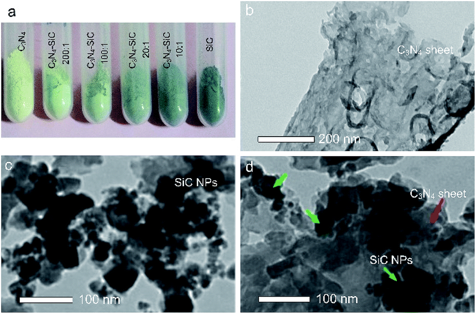 | ||
| Fig. 1 (a) Photograph of the g-C3N4, 3C-SiC NPs and the composite samples, (b) TEM image of g-C3N4 sheets, (c) TEM image of 3C-SiC NPs, and (d) TEM image of C3N4–SiC (20:1) composite, with the red arrow designating g-C3N4 and the green arrow pointing to 3C-SiC. | ||
XRD patterns of g-C3N4, 3C-SiC and the composite samples are shown in Fig. 2. The XRD pattern of the 3C-SiC NPs matched well with JCPDS No. 29-1129, demonstrating that the particles were indeed cubic 3C-SiC with good crystallinities. The grain size was estimated to be about 20 nm according to the Scherrer equation, and this agreed with the average size obtained from the TEM image in Fig. 1c. The XRD pattern of g-C3N4, which stacks like graphite with a triazine-based connection sheet as component unit, exhibits two characteristic diffraction peaks at around 27.3° and 13.1°.26 The results of the XRD pattern verify the formation of g-C3N4 by thermal treatment of melamine. In the XRD patterns of all the composite samples, diffraction peaks of g-C3N4 (yellow circles) can be constantly observed, whereas the intensities of the featured peaks of 3C-SiC (grey squares) depend on the mass fractions. Note that in the sample C3N4–SiC (100:1), weak diffraction peaks of 3C-SiC can be resolved whilst those features become negligible in the sample C3N4–SiC (200:1). No additional diffraction peaks appeared besides 3C-SiC and g-C3N4.
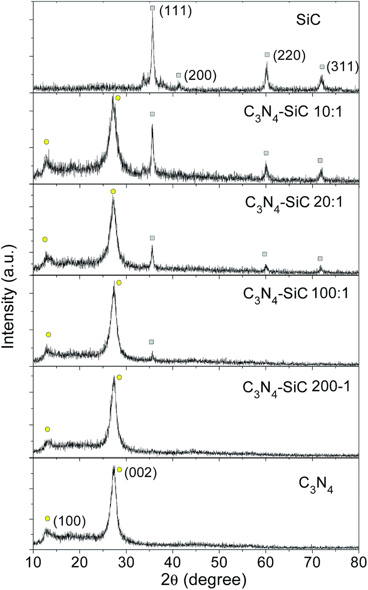 | ||
| Fig. 2 XRD patterns of 3C-SiC, g-C3N4 and their composite samples at various mass ratios, with yellow circles indicating the diffraction peaks of g-C3N4 and grey squares marking the diffraction peaks of 3C-SiC. | ||
TGA was used to study the formation of the nanocomposite (Fig. 3). All the tests were conducted from room temperature to 700 °C at a rate of 10 °C min−1 in air. The TGA result for 3C-SiC confirms that 3C-SiC is stable at temperatures up to 700 °C, which also suggests that no oxidation happened during the calcination step, and this is in agreement with the XRD results. Whereas, the 3C-SiC-melamine mixture (mass ratio = 1:100) exhibits a sharp weight loss at around 300 °C, which is mainly because of the transition from melamine to melem.7 A weight loss at about 550 °C was ascribed to the formation of g-C3N4 which could also be easily identified.
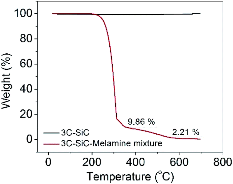 | ||
| Fig. 3 TGA results of 3C-SiC and 3C-SiC-melamine mixture. | ||
The structures were further investigated by examining the Raman spectra (Fig. 4a). The featured transverse optical (TO) mode at 790 cm−1 could be clearly distinguished in the spectrum of 3C-SiC NPs.37 A weak TO band of 3C-SiC could still be observed in the composite C3N4–SiC (10:1) without other peaks, indicating that the 3C-SiC NPs are stable under thermal treatment of 550 °C. However, because of the noticeable fluorescence of g-C3N4, the Raman modes for the spectra of the composites are largely hidden. UV-vis absorption spectra of all the samples were converted from diffuse reflectance spectra and are plotted in Fig. 4b. It was noticed that the absorption spectrum of 3C-SiC NPs shows no evident absorption edge, which is typical for indirect bandgap materials.
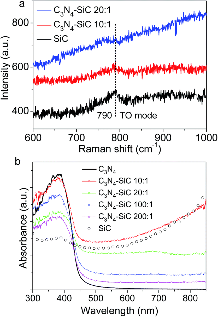 | ||
| Fig. 4 (a) Raman and (b) absorption spectra of 3C-SiC, g-C3N4 and composite samples. | ||
The absorption actually extended from 300 nm to 800 nm, which may be caused by phonon mediated optical absorption and band–tail transitions. Whereas, bare g-C3N4 mainly absorbs photons with a wavelength shorter than 460 nm. This means that, being decorated with 3C-SiC NPs, the absorption intensity of the 3C-SiC-NPs-decorated g-C3N4 composite is dramatically enhanced in the visible range. These absorption spectra are also consistent with the color variation shown in the photograph in Fig. 1a.
To gain an insight into the electron transition pathway, both steady-state and time-resolved PL spectra were measured. As shown in Fig. 5a, no remarkable fluorescence signal can be observed for the 3C-SiC NPs. Whereas, an apparent PL peak located at 470 nm can be observed in g-C3N4. The PL peak position matches well with the absorption edge, shown in Fig. 4b. With increasing fractions of 3C-SiC NPs, the PL intensity of the composite dramatically decreases, suggesting that the 3C-SiC NPs act as PL quenchers. It is worth noting that a blue shift presents with the increasing mass ratio of 3C-SiC in the composite, indicating that the formation of 3C-SiC-decorated g-C3N4 might induce electronic states with higher energy in the heterostructure. Time-resolved PL spectra and the enlargement shown in inset (Fig. 5b) clearly reveal that the PL decays faster when more 3C-SiC NPs are decorated on the g-C3N4 sheets. A graphic scheme of the electronic pathway of 3C-SiC-NPs-decorated g-C3N4 composite is illustrated in Fig. 6 using the PL results. Considering the bare g-C3N4, a simplified PL process can be described by nonradiative relaxation time τ1 and radiative recombination time τ2 irrespective of the detailed complex electronic structures:7
| I(t) = A + B1e−t/τ1 + B2e−t/τ2 | (1) |
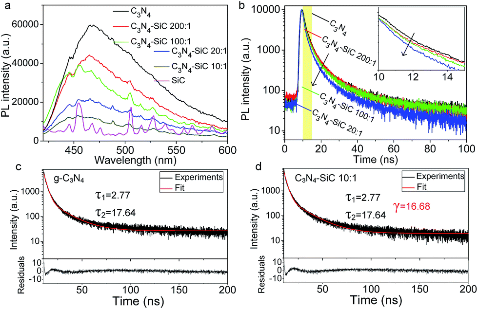 | ||
| Fig. 5 (a and b) PL and time-resolved PL spectra of 3C-SiC, g-C3N4 and composite samples. Inset of (b) is the enlargement of the selected window (yellow area). (c and d) Exponential fittings of two typical PL decay curves. Residuals versus independent plots are attached below (c and d). | ||
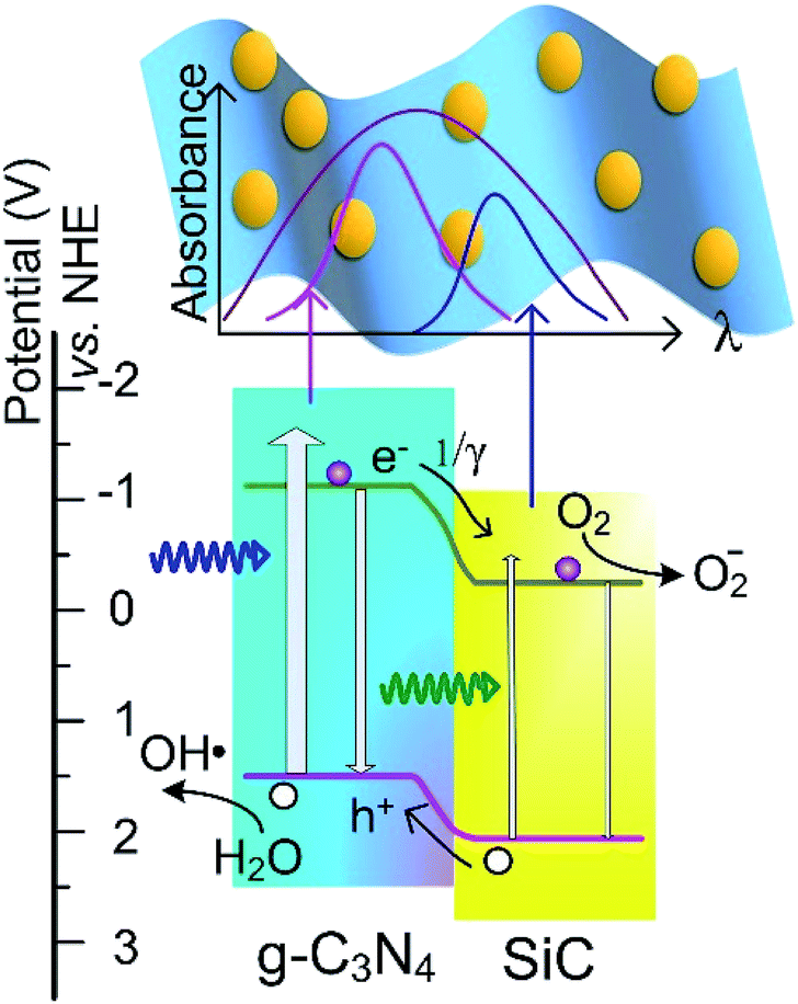 | ||
| Fig. 6 Diagram of the band structure illustrating the electron transition pathway and explaining the enhanced photocatalytic activity. NHE: normal hydrogen electrode. | ||
As shown in Fig. 5c, τ1 = 2.77 ns and τ2 = 17.64 ns are acquired. In the 3C-SiC/g-C3N4 composites, heterostructures form between 3C-SiC NPs and the g-C3N4 sheets. The band alignment of the heterostructure is drawn in Fig. 6 according to the reported band structures.3,36 The conduction band (CB) and valence band (VB) of g-C3N4 are reported to appear at −1.12 eV and 1.6 eV, respectively, whereas the CB and VB of 3C-SiC locate at −0.23 eV and 2.17 eV, respectively. Obviously, it is a Type-II staggered gap, in which photogenerated electrons would transfer to the 3C-SiC NPs and the holes move to g-C3N4, reducing the radiative recombinations. Thus, the 3C-SiC NPs play the role of PL quenchers. Designating the carrier transfer rate constant as 1/γ, the PL process should be described by a tri-exponential decay function:
| I(t) = A + B1e−t/τ1 + B2e−t/τ2 + Ce−t/γ | (2) |
This new electron transfer channel introduced by the heterostructure makes the PL decay faster and gives the effective separation of photogenerated carriers. By fixing τ1 and τ2 as 2.77 and 17.64 ns, respectively, the γ values can be obtained by numerical fitting (Fig. 5d). The γ values fitted from the PL decay curves are listed in Table 1. As the SiC content increases, the γ value drops from 1721.5 ns to 16.68 ns, indicating more 3C-SiC NPs provide higher carrier transfer rates within the composites. Thus, the heterostructure overcomes the issue of radiative recombination of the photogenerated electron–hole pairs in pure g-C3N4 by eventually enhancing the separation of photogenerated carriers. Furthermore, the 3C-SiC fills a major gap in the 460–600 nm optical absorption. Therefore, the metal free composites constructed using g-C3N4 and 3C-SiC could exhibit enhanced photocatalytic activity under visible light irradiation.
| Sample | C3N4–SiC (200:1) |
C3N4–SiC (100:1) |
C3N4–SiC (20:1) |
C3N4–SiC (10:1) |
|---|---|---|---|---|
| γ value (ns) | 1721.5 | 1117.7 | 691.0 | 16.68 |
As illustrated in Fig. 6, the generation of free radicals is crucial for the photodegradation. The generation of active hydroxyl radicals (˙OH) was confirmed via a fluorescent method by using TA as indicator. The TAOH emission at around 426 nm can be produced by the reaction of TA with ˙OH in a basic solution. Thus, the concentration of ˙OH in the solution could be detected by the fluorescent intensity. As shown in Fig. 7a, the PL intensity increased remarkably, together with irradiation time, thus verifying the generation of ˙OH by the g-C3N4. Similarly, the generation of ˙OH by C3N4–SiC was also confirmed (Fig. 7b). The time dependence of the PL intensity plotted in Fig. 7c shows that the PL intensity of TAOH generated by C3N4–SiC climbed faster, indicating an enhanced photocatalytic activity. In order to assess the stability of the C3N4–SiC composite, cycling tests were carried out (Fig. 7d). There is no noticeable deterioration in ˙OH generation rate after three cycles, indicating that the photocatalytic activity is quite stable.
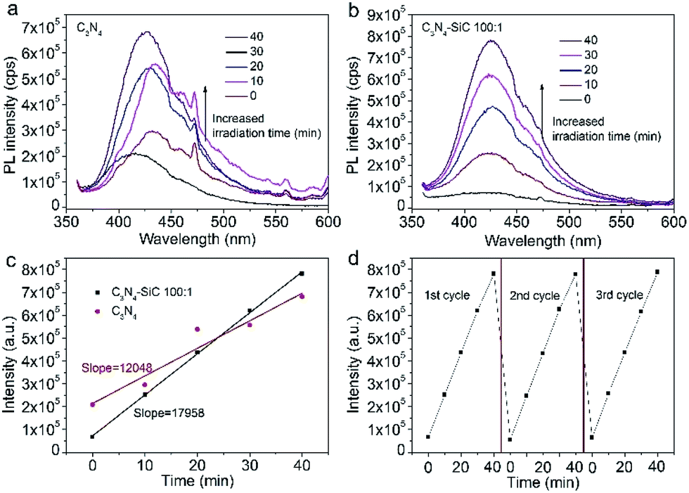 | ||
| Fig. 7 (a and b) PL spectra of TAOH in 3 mM TA and 0.01 M NaOH solution generated by g-C3N4 (a) and C3N4–SiC (100:1) (b) upon irradiation. (c) Time dependence of the PL intensity. (d) Cycling measurements of ˙OH generation. | ||
MO is one of the important dyes in industry, and frequently appears in waste water, but cannot be naturally degraded by microorganisms. Thus, photodegradation of MO was tested to evaluate the photocatalytic activity of the C3N4–SiC composite and the results obtained are plotted in Fig. 8. Clearly, without any photocatalyst, MO is resistant to visible light irradiation. For pure 3C-SiC NPs, less than 10% MO degraded in one hour, demonstrating that 3C-SiC NPs alone had poor photocatalytic activity. Whereas, about 40% MO was degraded over g-C3N4 alone, under the same experimental conditions, verifying that bare g-C3N4 is an excellent photocatalyst. Being decorated with a small amount of 3C-SiC NPs, the photocatalytic activity of the C3N4–SiC (100:1) composite dramatically increased and 55% of MO was degraded in one hour, which is a superior result compared to the bare g-C3N4. Especially, when the irradiation time was 20 min, 21.8% and 38.1% of the dyes were degraded by g-C3N4 and C3N4–SiC (100:1), respectively. The degradation rate was almost doubled by decoration of the SiC NPs. However, unlike the performance of the chemical composite with heterostructure, the direct mixture of g-C3N4 and 3C-SiC NPs at the mass ratio of 100:1 showed photocatalytic ability slightly worse than the bare g-C3N4 under identical conditions, suggesting that the enhanced photocatalytic performance of the composite essentially stemmed from the Type II heterostructure band alignment. Although the electron transfer rate was the fastest and optical absorption was the strongest in C3N4–SiC (10:1) out of all the tested composites, the experimental results in Fig. 8 showed a reduced photocatalytic activity for the degradation of MO compared to C3N4–SiC (100:1), which is logical considering that the higher addition ratio of 3C-SiC into the composites lowered the contact surface of the g-C3N4 sheets with MO and shields the light irradiation onto g-C3N4 sheets, thus leading to a weakened photocatalytic activity.
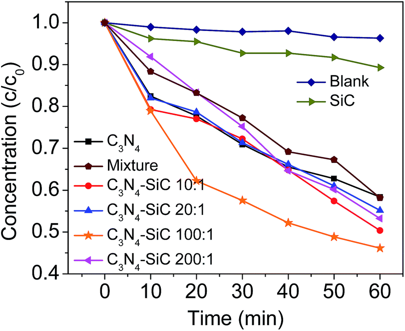 | ||
| Fig. 8 Photodegradation of MO over 3C-SiC NPs, g-C3N4 nanosheets and their composites. | ||
4. Conclusions
In summary, 3C-SiC-NP-decorated g-C3N4 composites were fabricated by heating a mixture of melamine and 3C-SiC NPs, which is highly repeatable and applicable for large-scale production at low cost without harming the environment. The composite structures were investigated using TEM, XRD and Raman spectroscopy. The enhanced light absorption and reinforced separation of photogenerated carriers revealed by absorption and PL spectra suggested an enhanced photocatalytic activity of the C3N4–SiC composite. The photodegradation results clearly showed that the nanocomposites fabricated with a mass ratio of melamine and 3C-SiC NPs at 100:1 exhibited an optimal photocatalytic activity and the corresponding removal rate of MO reached 55% in one hour, which is higher than the performance of bare g-C3N4 (40%) and pure 3C-SiC NPs (10%) at identical conditions, demonstrating an enhanced photocatalytic effect through Type II band alignment between the 3C-SiC NPs and g-C3N4 sheets within the composite.
Conflicts of interest
The authors declare that they have no conflict of interest.Acknowledgements
This work was jointly supported by National Natural Science Foundation of China (No. 11604155 and 11604147), China Postdoctoral Science Foundation (No. 2016M600428 and 2017T100386), Jiangsu Planned Projects for Postdoctoral Research Funds (No. 1601023A) and the K. C. Wong Magna Fund in Ningbo University.References
- J. Liu, Y. Liu, N. Y. Liu, Y. Z. Han, X. Zhang, H. Huang, Y. Lifshitz, S. T. Lee, J. Zhong and Z. H. Kang, Science, 2015, 347, 970 CrossRef CAS PubMed.
- S. W. Cao and J. G. Yu, J. Phys. Chem. Lett., 2014, 5, 2101 CrossRef CAS PubMed.
- B. Y. Peng, S. S. Zhang, S. Y. Yang, H. J. Wang, H. Yu, S. Q. Zhang and F. Peng, Mater. Res. Bull., 2014, 56, 19 CrossRef CAS.
- Y. L. Tian, B. B. Chang, J. Fu, B. C. Zhou, J. Y. Liu, F. N. Xi and X. P. Dong, J. Solid State Chem., 2014, 212, 1 CrossRef CAS.
- H. Y. Guo, J. Y. Zhang, L. Ma, J. L. Chavez, L. Q. Yin, H. Gao, Z. L. Tang and W. Chen, Adv. Funct. Mater., 2015, 25, 6833 CrossRef CAS.
- Y. W. Yuan, L. L. Zhang, J. Xing, M. I. B. Utama, X. Lu, K. Z. Du, Y. M. Li, X. Hu, S. J. Wang, A. Genç, R. Dunin-Borkowski, J. Arbiold and Q. H. Xiong, Nanoscale, 2015, 7, 12343 RSC.
- Z. X. Gan, Y. Shan, J. R. Chen, Q. F. Gui, Q. Z. Zhang, S. P. Nie and X. L. Wu, Nano Res., 2016, 9, 1801 CrossRef CAS.
- L. Y. Chen, X. S. Zhou, B. Jin, J. Luo, X. Y. Xu, L. L. Zhang and Y. P. Hong, Int. J. Hydrogen Energy, 2016, 41, 7292 CrossRef CAS.
- Y. F. Chen, W. X. Huang, D. L. He, Y. Situ and H. Huang, ACS Appl. Mater. Interfaces, 2014, 6, 14405 CAS.
- H. J. Yan and H. X. Yang, J. Alloys Compd., 2011, 509, L26 CrossRef CAS.
- J. G. Yu, S. H. Wang, J. X. Low and W. Xiao, Phys. Chem. Chem. Phys., 2013, 15, 16883 RSC.
- J. X. Sun, Y. P. Yuan, L. G. Qiu, X. Jiang, A. J. Xie, Y. H. Shen and J. F. Zhu, Dalton Trans., 2012, 41, 6756 RSC.
- Y. J. Wang, R. Shi, J. Lin and Y. F. Zhu, Energy Environ. Sci., 2011, 4, 2922 CAS.
- R. Yin, Q. Z. Luo, D. S. Wang, H. T. Sun, Y. Y. Li, X. Y. Li and J. An, J. Mater. Sci., 2014, 49, 6067 CrossRef CAS.
- A. Zada, M. Humayun, F. Raziq, X. L. Zhang, Y. Qu, L. L. Bai, C. L. Qin, L. Q. Jing and H. G. Fu, Adv. Funct. Mater., 2016, 6, 1601190 Search PubMed.
- F. Raziq, Y. Qu, M. Humayun, A. Zada, H. T. Yu and L. Q. Jing, Appl. Catal., B, 2017, 201, 486 CrossRef CAS.
- X. Chen, B. H. Zhou, S. L. Yang, H. S. Wu, Y. X. Wu, L. D. Wu, J. Pan and X. Xiong, RSC Adv., 2015, 5, 68953 RSC.
- Z. Z. Lou and C. Xue, CrystEngComm, 2016, 18, 8406 RSC.
- D. S. Wang, Z. X. Xu, Q. Z. Luo, X. Y. Li, J. An, R. Yin and C. Bao, J. Mater. Sci., 2016, 51, 893 CrossRef CAS.
- J. Fu, B. B. Chang, Y. L. Tian, F. N. Xia and X. P. Dong, J. Mater. Chem. A, 2013, 1, 3083 CAS.
- J. Ren, Y. Y. Chai, Q. Q. Liu, L. Zhang and W. L. Dai, Appl. Surf. Sci., 2017, 403, 177 CrossRef CAS.
- Y. Wang, Z. Wang, S. Muhammad and J. He, CrystEngComm, 2012, 14, 5065 RSC.
- C. S. Pan, J. Xu, Y. Wang, D. Li and Y. F. Zhu, Adv. Funct. Mater., 2012, 22, 1518 CrossRef CAS.
- Y. J. Wang, X. J. Bai, C. S. Pan, J. He and Y. F. Zhu, J. Mater. Chem., 2012, 22, 11568 RSC.
- T. Li, L. Zhao, Y. He, J. Cai, M. Luo and J. Lin, Appl. Catal., B, 2013, 129, 255 CrossRef CAS.
- S. C. Yan, Z. S. Li and Z. G. Zou, Langmuir, 2010, 26, 3894 CrossRef CAS PubMed.
- N. Komarevskiy, V. Shklover, L. Braginsky, C. Hafner and J. Lawson, Opt. Express, 2012, 20, 14189 CrossRef CAS PubMed.
- C. Y. He, X. L. Wu, J. C. Shen and P. K. Chu, Nano Lett., 2012, 12, 1545 CrossRef CAS PubMed.
- D. H. van Dorp, N. Hijnen, M. D. Vece and J. J. Kelly, Angew. Chem., Int. Ed., 2009, 48, 6085 CrossRef CAS PubMed.
- X. L. Wu, J. Y. Fan, T. Qiu, X. Yang, G. G. Siu and P. K. Chu, Phys. Rev. Lett., 2005, 94, 026102 CrossRef CAS PubMed.
- J. Zhang, L. Z. Liu, L. Yang, Z. X. Gan, X. L. Wu and P. K. Chu, Appl. Phys. Lett., 2014, 104, 231902 CrossRef.
- X. F. Zhou, X. Li, Q. Z. Gao, J. L. Yuan, J. Q. Wen, Y. P. Fang, W. Liu, S. S. Zhang and Y. J. Liu, Catal. Sci. Technol., 2015, 5, 2798 CAS.
- Y. Peng, G. Han, D. Wang, K. X. Wang, Z. N. Guo, J. J. Yang and W. X. Yuan, Int. J. Hydrogen Energy, 2017, 42, 14409 CrossRef CAS.
- X. Liao, J. J. Chen, M. M. Wang, Z. X. Liu, L. J. Ding and Y. Li, J. Alloys Compd., 2016, 658, 642 CrossRef CAS.
- X. Liao, Z. X. Liu, L. J. Ding, J. J. Chen and W. H. Tang, RSC Adv., 2015, 5, 99143 RSC.
- B. Wang, J. T. Zhang and F. Huang, Appl. Surf. Sci., 2017, 391, 445 Search PubMed.
- L. Z. Liu, J. Wang, X. L. Wu, T. H. Li and P. K. Chu, Opt. Lett., 2010, 35, 4024 CrossRef CAS PubMed.
| This journal is © The Royal Society of Chemistry 2017 |