 Open Access Article
A dual-faced interlayer prepared by electron beam evaporation for enhanced-performance lithium–sulfur batteries
Qiong Tang ab,
Heqin Li*a,
Jing Zhangab,
Zhiwei Lina,
Yuanyuan Pana,
Qingzhuo Hua,
Yu Youb and
Yangwei Yeb
aSchool of Materials Science and Engineering, Hefei University of Technology, Hefei 230009, China. E-mail: lhqjs@hfut.edu.cn
bSchool of Electronic Science and Applied Physics, Hefei University of Technology, Hefei 230009, China
First published on 12th September 2017
Abstract
In this work, a dual-faced carbon paper was prepared by depositing Al2O3 on one side of carbonized filter paper via the technique of electron beam evaporation. Assembled into Li–S batteries, the Al2O3-deposited carbon paper served as a multifunctional interlayer. The cathode of 70% sulfur content with this interlayer presented notable enhancements in electrochemical performance in contrast to that with a single carbon interlayer. At a current rate of 0.5C, the battery with the Al2O3-deposited carbon interlayer delivered a high initial capacity of 1253 mA h g−1 and retention of 700 mA h g−1 over 120 cycles, while the battery with the carbon interlayer delivered an approximate initial capacity of 1117 mA h g−1 but much poorer retention of 441 mA h g−1 over 87 cycles. The carbon side of the interlayer was placed toward the cathode as the upper current collector, which ensured the conductivity of the contact interface with the active material and promoted activation of sulfur. At the same, Al2O3 as a polar material facing toward the separator impeded the leakage of soluble polysulfides and mitigated the shuttle effect by chemical adsorption of soluble polysulfides. Combined with the interstitial structure of the interlayer acting as a physical container, Li–S batteries with this novel interlayer demonstrate superiorities in capacity, variable discharge/charge rate, Electrochemical Impedance Spectroscopy (EIS) and Cyclic Voltammetry (CV) characteristics.
1. Introduction
The lithium–sulfur (Li–S) battery has been explored for decades due to its high theoretical specific energy density (2600 mW h g−1) and capacity (1675 mA h g−1), far exceeding those of prevailing Li-ion batteries.1–3 These characteristics combined with the wide distribution and environmental friendliness of sulfur enable the Li–S battery to be one of the most promising energy storage devices to satisfy the demands for high capacity and long endurance. Nevertheless, this system is confronted with some challenges. Its practical capacity is lower than the theoretical value due to the poor conductivity of sulfur and the cathode structure is apt to collapse for the volume change of 79.2% from sulfur to the reduction Li2S2/Li2S. Primarily, soluble polysulfide intermediates give rise to “shuttle effect” that leads to sulfur loss, damages cycle stability and reduces coulombic efficiency.4–9 Efforts have been extensively devoted to addressing these problems. Carbonaceous materials as sulfur hosts can not only establish conductive framework but also relieve “shuttle effect” by physical absorption of carbon pores.10–14 Modified carbon materials by doping element N or functional group intensify the adsorption of polysulfides by chemical interaction.15–20 Conductive polymers are also introduced to mitigate diffusion of polysulfides from the cathode.21–23 Although these methods improved the capability of Li–S battery, the inevitable shortcomings lie in complicate fabrication of materials and low sulfur content in cathode.Recently, the insertion of carbon interlayer between pure sulfur cathode and separator attracts people's attention. Carbon interlayer prepared by convenient manufacture serves as both the upper current collector and barrier of soluble polysulfide intermediates.24–28 However, it is noted that physical interaction between nonpolar carbon and polar sulfides is limited.17 Therefore, it is necessary to modify carbon interlayer to intensify the inhibition of shuttle effect.
In traditional configuration, polar metal oxides (such as Al2O3, TiO2, MnO2, and SnO2) have been added into S/C cathode to improve the chemical adsorption of polysulfides by strong electrostatic attraction of metal–oxygen bond.29–32 Inspired by the idea, we applied the technique of electron beam evaporation (EBE) to deposit Al2O3 on carbon paper made by carbonizing commercial filter paper. Fig. 1 is the schematic illustrations of manufacturing material and assembling battery. Electron beam evaporation as a method of physical vapor deposition can produce nano-scale material coating of pure phase on the substrate with benign adhesivity at a high deposition speed. This technique has been applied in Li-ion battery to obtain great improvement of performance.33 To the best of our knowledge, it has not been reported to be applied in Li–S battery. Furthermore, the Al2O3-deposited dual-faced carbon interlayer is also seldom reported in literatures. The carbon side of the interlayer toward the cathode serves as a conductive reservoir with physical interception of sulfur series. The Al2O3 side toward the separator serves as a lock gate to obstruct leaky sulfides. Li–S battery with this novel interlayer demonstrates remarkable enhancement of performances compared to that with single carbon interlayer. We systematically investigated the effects of the Al2O3-deposited interlayer on capabilities of Li–S battery.
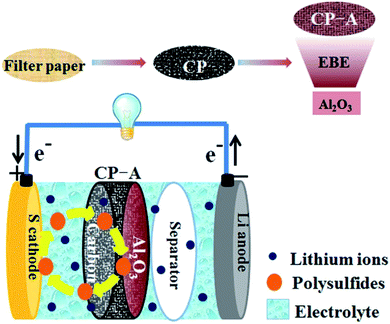 | ||
| Fig. 1 Schematic illustrations of preparing Al2O3-deposited carbon paper and the configuration of the Li–S battery with CP-A interlayer. | ||
2. Experimental section
2.1 Preparation of sulphur cathode
70 wt% sulfur powder (chemical purity, Sinopharm Chemical Reagent Co., Ltd.) and 20 wt% acetylene black (purity 99.9%, Shanxi Luan Group Co., Ltd.) were ground uniformly in an agate mortar, then directly mixed with 10 wt% polyvinylidene fluoride (PVDF) (Arkema HSV900, France) in N-methyl-2-pyrrolidinone (NMP) (purity 99.9%, Sinopharm Chemical Reagent Co., Ltd.) to form homogeneous slurry. The slurry was casted on Al foil (purity 99.8%, 20 μm thick) and dried at 50 °C for 24 hours. Next, it was punched into disks of 12 mm in diameter as sulfur cathodes. The sulfur loading is 0.70.8 mg cm−2.2.2 Preparation of interlayer
A free-standing carbon paper was prepared by calcining commercial filter paper (Hangzhou Special Paper Co., Ltd.) at 1000 °C for 2 hours under argon atmosphere in a tube furnace, with a heating rate of 3 °C min−1 and a flow rate of 30 mL min−1. When cooled down to ambient temperature, prepared carbon paper with thickness of about 80 μm (measured by a vernier gauge) was directly placed in an electron-beam evaporator (DZS-500, China) for Al2O3 deposition. The base pressure of vacuum chamber is 7.0 × 10⁻⁴ Pa. Under the current of electron beam of 40 mA, Al2O3 target (purity 99.5%) loaded into a Cu crucible was pre-evaporated until the rate indicator was 1 Å s−1. Then the shutter was opened and Al2O3 was evaporated for 200 seconds on one face of the carbon paper substrate. The carbon papers with and without Al2O3 deposition are named after CP-A and CP, respectively. Both were cut into circle slices of 12 mm in diameter as interlayers.2.3 Material characterization
The morphologies and element mappings of the synthesized material were observed using field-emission scanning electron microscopy (FESEM) on SU8020 (Hitachi, Japan) combined with energy dispersive X-ray spectroscopy (EDS). X-ray photoelectron spectroscopy (XPS) measurement was performed on a Thermo ESCALAB 250 energy spectrometer (USA) with a monochromatic Al Kα (1486.60 eV) X-ray source. All binding energies were labeled taking C 1s at 284.8 eV as a reference according to the testing environment. Current–Voltage (I–V) tests of interlayers were carried out on a Keithley 4200 semiconductor characterization system (USA) to compare the resistances of carbon paper before and after Al2O3 deposition.2.4 Electrochemical measurements
Three kinds of CR2032-type coin cells were assembled with bare S cathode, the S cathode with CP and with CP-A interlayer, respectively. Lithium foil (purity 99.95%, 0.6 mm thick and 15.8 mm in diameter) was used as anodic electrode and Celgard 2400 as separator. The electrolyte purchased from Suzhou Qianmin Chemical Reagent Co., Ltd. was 1 M bis(trifluoromethane) sulfonamide lithium salt (LITFSI) dissolved in a mixed solution of 1,3-dioxolane (DOL) and dimethyl ether (DME) (1![[thin space (1/6-em)]](https://www.rsc.org/images/entities/char_2009.gif) :
:![[thin space (1/6-em)]](https://www.rsc.org/images/entities/char_2009.gif) 1, v/v) with 1 wt% LiNO3 added.
1, v/v) with 1 wt% LiNO3 added.
The cells were assembled in an argon-filled glove box (Etelux Lab 2000, China) with oxygen and water contents below 0.1 ppm. Galvanostatic cycling tests were conducted between 1.5 and 3.0 V on a Neware BTS2300 system (Shenzhen, China) at room temperature. Cyclic Voltammetry (CV) measurements were performed at a scan rate of 0.2 mV s−1 and electrochemical impedance spectra (EIS) measurements were conducted from 100 kHz to 0.1 Hz with potentiostatic amplitude of 5 mV on a CHI 760D (Shanghai, China) electrochemical workstation.
3. Results and discussion
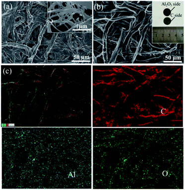
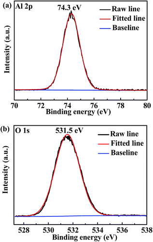
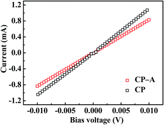
The carbon paper has a netlike structure of weaved and stacked fibers as shown in Fig. 2(a). And the magnification image demonstrates there is a hierarchical pore size distribution in fibers, which contributes to the accommodation of sulfur series, ion transfer and infiltration of electrolyte.10 After depositing Al2O3, no apparent particle or bulk can be observed form the SEM image of Fig. 2(b). However, Al2O3 side of the carbon paper appears to be darker compared with the carbon side without deposition, as shown in the inset. In addition, distributions of element aluminum and oxygen shown in Fig. 2(c) confirm one side of the carbon paper has been homogeneously coated by Al2O3 referenced to the distribution of carbon. The chemical state of the deposition was further investigated by XPS analysis. The peak at 74.3 eV of Al 2p spectrum shown in Fig. 3(a) and the peak at 531.5 eV of O 1s spectrum shown in Fig. 3(b) correspond to the binding energies of Al3+ and O2− in Al2O3, respectively and no metallic Al or other valence state of Al exists, which agrees well with the element mappings.34The resistances of CP and CP-A were measured by I–V tests as shown in Fig. 4. The samples were cut into the same size of squares with 1 cm in length, and silver glue was painted on two opposite sides of each square. I–V results were obtained by probes contacting on the two sides with silver glue. Both straight lines show reversible ohm characteristics in a sweep voltage range of −0.01 to +0.01 V, which means deposition of Al2O3 did not induce extra contact potential barrier that is so-called Schottky effect, and thereby did not change the transport property of electron. By calculating the slopes of straight lines, the ohm resistances of CP and CP-A are separately 9.3 and 12.5 ohm, which indicates the conductivity of carbon paper reduces after being coated by insulating Al2O3. Therefore, the conductive carbon side of interlayer is supposed to face toward the cathode with high sulfur loading, resulting into good conductive interface to activate sulfur as upper current collector. During discharge, soluble intermediates first encounter the intercept of physical barrier and further chemical adsorption from polar Al2O3 facing toward the separator.
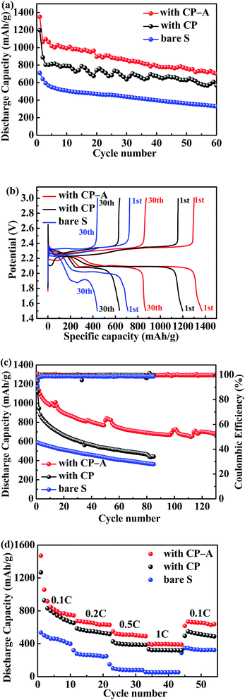
The electrochemical performances of the bare S cathode, S cathode with CP interlayer and S cathode with CP-A interlayer for Li–S batteries were investigated. In Fig. 5(a), the Li–S battery with CP-A interlayer presents the initial discharge capacity of 1352 mA h g−1 at 0.2C (1C = 1675 mA g−1) approaching to 81% utilization of sulfur, higher than 1198 mA h g−1 of the battery with CP interlayer. Although the faces to cathodes are both conductive carbon in these two batteries, the extra deposited Al2O3 in CP-A mitigates the escape of soluble polysulfides from interlayer during discharge, and these reduction products intercepted into interlayer are reactivated. In result, the battery with CP-A interlayer delivers higher initial capacity. Over 60 cycles the battery with CP-A interlayer retains the highest reversible capacity of 701 mA h g−1. Compared with 569 mA h g−1 of the battery with CP interlayer, it can be deduced that Al2O3 effectively alleviates the decay of capacity. On the other hand, the poor initial capacity (711 mA h g−1) and 60th capacity (329 mA h g−1) of the bare sulfur electrode shows inferior sulfur utilization and capacity retention.
Fig. 5(b) is the 1st and 30th discharge/charge profiles of three samples at 0.2C, which all exhibit two typical discharge plateaus of Li–S batteries. The higher plateau at about 2.3–2.2 V corresponds to the transformation from sulfur to soluble Li2Sx (4 ≤ x ≤ 8), and the lower at about 2.1–2.0 V corresponds to the formation of insoluble Li2S2/Li2S.35,36 It is noticed that for the bare S cathode and the S cathode with CP interlayer, the voltage gaps between the second discharge and charge plateaus gradually increase as discharge/charge cycles increase. On the contrary, no evident change is detected in the S cathode with CP-A interlayer. Moreover, the voltage gap of the S cathode with CP-A interlayer is always the narrowest, whether in the 1st or 30th cycle. It is attributed to the adsorption of polysulfides by Al2O3 that inhibits the shuttle effect and reduces the polarization of Li–S battery. Besides, the low-voltage plateaus of S cathode with CP-A interlayer are both longer than the others, suggesting more soluble polysulfides intercepted to participate in reduction reaction and produce more discharge capacity.
To further investigate the effect of CP-A interlayer, discharge/charge cycles at 0.5C and variable rate were tested. At 0.5C as shown in Fig. 5(c), the batteries with bare sulfur cathode, CP-A interlayer and CP interlayer deliver initial capacities of 588 mA h g−1, 1253 mA h g−1 and 1117 mA h g−1, respectively. After 85 cycles, the specific capacities of the bare sulfur cathode and the cathode with CP separately reduce to 441 mA h g−1 and 361 mA h g−1, while the cathode with CP-A delivers desirable capacity of 700 mA h g−1 even after 120 cycles, presenting superior capability and extended cycling life. Furthermore, the cathode with CP drops in capacity by more than 50% after 85 cycles, while the cathode with CP-A drops in capacity by less than 50% after 120 cycles. For the bare S cathode, although the dropping ratio of capacity is close to that for the cathode with CP-A, it can be observed that the capacity obtained from the S cathode is less than 50% of that observed from the cathode with CP-A. This is probably because that on account of bad conductivity of the S cathode, only a small amount of active material could participate in reaction and accordingly the small amount of soluble polysulfides could be effectively blocked only by conventional separator. However, when the conductive interlayer was inserted, the capacity of the sulfur cathode was largely released. In result, the dropping ratio of capacity of the cathode with CP is even higher than that for the S cathode. But the cathode with CP-A has both benign sulfur utilization and capacity retaining. As for coulombic efficiency, the introduction of LiNO3 in electrolyte makes all batteries more than 95%. Fig. 5(d) is the variable rate test from 0.1C to 1C. Capacities of batteries gradually decay ascribed to gradually severe polarization as rate increases. Even so, the cathode with CP-A interlayer delivers the highest capacity in every rate stage and when rate returns to 0.1C, it can also regain the majority of capacity, presenting the highest discharge capacity among the samples. Therefore, the cathode with CP-A interlayer not only improves the cycle capability, but also exhibits very good reversible behaviour.
EIS tests of the S cathode with CP interlayer and S cathode CP-A interlayer were performed before cycling, respectively. Both curves in Fig. 6 display the analogy profiles with a semicircle in high frequency corresponding to charge transfer resistance and an inclined line in low frequency corresponding to ion diffusion resistance. Differently, for the cathode with CP-A, the left point of intersection of the semicircles and abscissa axis shifts right a little compared with the cathode with CP, which denotes it has a little higher internal resistance which originates from the ohm resistances of electrolyte, electrode materials, current collector and contact interface.37 This is because non-conductive Al2O3 increases the ohm resistance of the electrode material in accordance with the analysis of I–V test. Nevertheless, the much smaller diameter of the semicircle signifies the battery with CP-A interlayer possesses a much lower charge transfer resistance than that with CP interlayer. This is possibly because deposited Al2O3 particles not only have adsorption of polysulfides but also increase the contact sites with electrolyte leading to more electrolyte uptake. The synergetic effects facilitate the charge transfer. The result supports the superior cycling capability of the battery with CP-A interlayer.
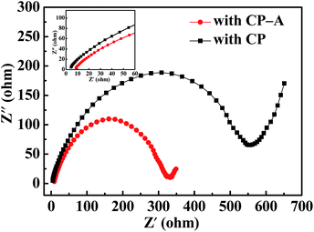 | ||
| Fig. 6 EIS curves of the batteries with CP and CP-A interlayers and the inset of enlarge curves at a small scale. | ||
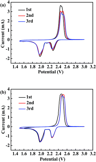
Fig. 7 shows the CV profiles of the batteries with CP and with CP-A interlayer, respectively with typical CV shapes of conventional Li–S batteries. It is noteworthy that the initial CV cycles of both batteries obviously deviate from the subsequent two cycles, which is ascribed to the activation of batteries and redistribution of sulfur on favorable sites.38 Besides, one broad oxidation peak in the initial scan evolves into two adjacent peaks at around 2.45–2.48 V and 2.47–2.52 V in the next scans, also indicating electrochemical activation has taken place.39 These two oxidation peaks correspond to the oxidation of Li2S2/Li2S to polysulfides and then to sulfur, and the reduction peaks at about 1.96–1.98 V and 2.26–2.27 V correspond to the reduction of sulfur to Li2Sx (4 ≤ x ≤ 8) and then to Li2S2/Li2S.40 Differently, the CV profiles of the battery with CP-A interlayer almost overlap after the initial cycle and the peak intensity has no obvious change as shown in Fig. 7(b), suggesting benign electrochemical reversibility and slow capacity fading. Contrarily, the profiles of the battery with CP interlayer shown in Fig. 7(a) in the following two cycles change evidently and peak intensities decrease distinctly. Furthermore, in terms of the peak positions, the reduction peaks shift lower and the oxidation peaks shift higher in the battery with CP interlayer, indicating continually enlarged polarization during redox. While no shift is detected in the battery with CP-A interlayer, indicating the electrochemical state is stable and polarization has not been deteriorated. The observations of CV profiles agree well with the electrochemical performances of the two kinds of batteries.
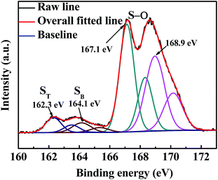
We disassembled a coin cell at the state of full charge after 100 discharge/charge cycles and washed the CP-A interlayer with 1,3-dioxolane solvent in a glove box for ex situ characterization. The FESEM images of the face and cross sections with corresponding element mappings are shown in Fig. 8. The interlayer morphology of a netlike structure was retained and no apparent fracture of fibers is observed from Fig. 8(a). What's more, compared to the initial thickness of about 80 μm of carbon paper, the thickness of cross section almost has no change as shown in Fig. 8(b). That means the interlayer has prominent mechanical strength to endure the volume change during discharge/charge reaction. Al2O3 as a kind of ceramic material is conducive to enhancing the rigidity of carbon paper to keep integrity of carbon paper even after 100 cycles. Some dark areas can be observed in the interlaced structure of carbon paper as shown in Fig. 8(b) FESEM picture. Because the carbon paper has plenty of pores and holes, and the escaped polysulfides could not fill up all the interspaces entirely and they may adhere to the surfaces of carbon fibers or fill in more small pores so that relative large voids are visible from the picture. Additionally, although no bulk sulfur-series particles can be observed from the image, the EDS mappings of element C, O, Al and S indicate sulfur series are effectively intercepted into the interlayer. This also can be confirmed by ex situ high-resolution S 2p XP spectrum of the cycled CP-A interlayer shown in Fig. 9. It is noted that only the 2p3/2 component of the 2p3/2/2p1/2 doublet is labeled as convention. Each S 2p3/2/2p1/2 doublet was fitted according to the principle that the peak area ratio is 2![[thin space (1/6-em)]](https://www.rsc.org/images/entities/char_2009.gif) :
:![[thin space (1/6-em)]](https://www.rsc.org/images/entities/char_2009.gif) 1, with 1.2 eV of splitting energy and same full width at half maximum. The binding energy located at 167.1 and 168.9 eV are attributed to S–O bonding with characteristics of sulphite and sulphate, which originate from residual bis(trifluoromethane) sulfonamide lithium salt (LITFSI) and exposure to air outside glove box before test, respectively.41 The binding energy of 164.1 eV is assigned to bridging S (SB) originating from element sulfur. The binding energy of 162.3 eV is assigned to terminal S (ST) originating from polysulfide compounds, indicating reduction intermediates deviating from cathode are hold up and retained into CP-A interlayer for reutilization.42–44 These ex situ characterizations are consistent with previous electrochemical analyses.
1, with 1.2 eV of splitting energy and same full width at half maximum. The binding energy located at 167.1 and 168.9 eV are attributed to S–O bonding with characteristics of sulphite and sulphate, which originate from residual bis(trifluoromethane) sulfonamide lithium salt (LITFSI) and exposure to air outside glove box before test, respectively.41 The binding energy of 164.1 eV is assigned to bridging S (SB) originating from element sulfur. The binding energy of 162.3 eV is assigned to terminal S (ST) originating from polysulfide compounds, indicating reduction intermediates deviating from cathode are hold up and retained into CP-A interlayer for reutilization.42–44 These ex situ characterizations are consistent with previous electrochemical analyses.
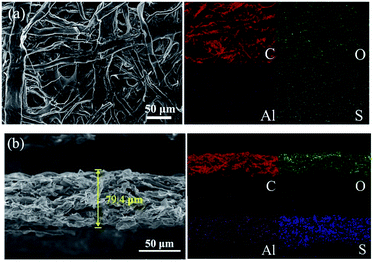 | ||
| Fig. 8 FESEM images of (a) the face and (b) cross sections with their corresponding element mappings for CP-A interlayer after cycling. | ||
Table 1 is a comparison with other reported interlayers in recent years. It indicates the Li–S battery with the CP-A interlayer presents comparable electrochemical performances by uncomplicated fabrication.
| Sample | Major fabrication steps | Sulfur content (wt%) | Sulfur loading (mg cm−2) | Initial discharge capacity (mA h g−1) | Rate | Residual capacity (mA h g−1) | Ref. |
|---|---|---|---|---|---|---|---|
| GO/CNT | Hummers method, chemical vapor deposition, ultrasonic mixing, vacuum filtration | 70 | 1.0 | 1370 | 336 mA g−1 | 671 (300 cycles) | 45 |
| PEDOT:PSS–CNT | Treating with H2SO4 two times and acetone one time, ultrasonic mixing, vacuum filtration | 60 | 0.7–0.8 | 921 | 0.5C | 653 (200 cycles) | 46 |
| W18O49 nanowire | Solvothermal route, coating slurry | 70 | 1.9 | 1142 | 0.5 A g−1 | 809 (50 cycles) | 47 |
| Cross-stacked carbon nanotube | Chemical vapor deposition, laser cutting | 60 | Not given | 930 | 0.1C | 641 (100 cycles) | 48 |
| Electrospun carbon nanofibers | High-voltage electrospinning, calcination | 80 | 4.5 | 1070 | 0.1C | 477 (100 cycles) | 49 |
| CP-A | Calcination, EBE | 70 | 0.7–0.8 | 1253 | 0.5C | 700(120 cycles) | This work |
4. Conclusions
Al2O3-deposited carbon paper by the EBE technique as interlayer is inserted into the traditional Li–S battery.Compared with the sulfur cathode with CP interlayer, the electrochemical performances of that with CP-A interlayer are notably enhanced. We conclude that firstly, the Al2O3 coating raises the mechanical strength of carbon paper, enables physical morphology of the interlayer intact to undertake large volume change during discharge/charge cycles. Secondly, the two-faced interlayer ensures good conductivity of interface between cathode and the carbon side. Lastly, chemical adsorption of polar sulfur species by polar Al2O3 has stronger inhibition of shuttle effect than physical absorption of nonpolar porous carbon. Besides, extra contact sites brought by deposition may raise the uptake of electrolyte to facilitate electrochemical reaction. In all, this method of physical vapor deposition provides an effectual avenue for manufacturing material applied in Li–S batteries.
Conflicts of interest
There are no conflicts to declare.Acknowledgements
The authors gratefully acknowledge the support of the “Strategic Priority Research Program” of the Chinese Academy of Science (Grant No. XDA03040000).References
- P. G. Bruce, S. A. Freunberger and L. J. Hardwick, et al., Nat. Mater., 2012, 11, 19–29 CrossRef CAS PubMed.
- J. Wang, Y. Wu and Z. Shi, et al., Electrochim. Acta, 2014, 144, 307–314 CrossRef CAS.
- B. Zhang, X. Qin and G. R. Li, et al., Energy Environ. Sci., 2010, 3, 1531–1537 CAS.
- A. Manthiram, Y. Fu and Y. S. Su, Acc. Chem. Res., 2012, 46, 1125–1134 CrossRef PubMed.
- A. Manthiram, Y. Fu and S. H. Chung, et al., Chem. Rev., 2014, 114, 11751–11787 CrossRef CAS PubMed.
- S. S. Zhang, J. Power Sources, 2013, 231, 153–162 CrossRef CAS.
- S. Evers, T. Yim and L. F. Nazar, J. Phys. Chem. C, 2012, 116, 19653–19658 CAS.
- Y. Yang, G. Zheng and Y. Cui, Chem. Soc. Rev., 2013, 42, 3018–3032 RSC.
- X. Ji and L. F. Nazar, J. Mater. Chem., 2010, 20, 9821–9826 RSC.
- H. Ye, Y. X. Yin and S. Xin, et al., J. Mater. Chem. A, 2013, 1, 6602–6608 CAS.
- R. Sahore, L. P. Estevez and A. Ramanujapuram, et al., J. Power Sources, 2015, 297, 188–194 CrossRef CAS.
- J. T. Lee, Y. Zhao and H. Kim, et al., J. Power Sources, 2014, 248, 752–761 CrossRef CAS.
- Y. Zhang, Y. Zhao and A. Konarov, et al., J. Alloys Compd., 2015, 619, 298–302 CrossRef CAS.
- M. Depardieu, R. Janot and C. Sanchez, et al., RSC Adv., 2014, 4, 23971–23976 RSC.
- S. Wang, Z. Zhao and H. Xu, et al., Electrochim. Acta, 2015, 173, 282–289 CrossRef CAS.
- Y. Qu, Z. Zhang and X. Zhang, et al., Carbon, 2015, 84, 399–408 CrossRef CAS.
- J. Song, T. Xu and M. L. Gordin, et al., Adv. Funct. Mater., 2014, 24, 1243–1250 CrossRef CAS.
- J. Qu, S. Lv and X. Peng, et al., J. Alloys Compd., 2016, 671, 17–23 CrossRef CAS.
- L. Ji, M. Rao and H. Zheng, et al., J. Am. Chem. Soc., 2011, 133, 18522–18525 CrossRef CAS PubMed.
- L. Zhang, L. Ji and P. A. Glans, et al., Phys. Chem. Chem. Phys., 2012, 14, 13670–13675 RSC.
- J. Wang, J. Yang and J. Xie, et al., Adv. Mater., 2002, 14, 963–965 CrossRef CAS.
- W. Zhou, Y. Yu and H. Chen, et al., J. Am. Chem. Soc., 2013, 135, 16736–16743 CrossRef CAS PubMed.
- Y. Zhang, Y. Zhao and A. Yermukhambetova, et al., J. Mater. Chem. A, 2013, 1, 295–301 CAS.
- Y. S. Su and A. Manthiram, Chem. Commun., 2012, 48, 8817–8819 RSC.
- C. Zu, Y. S. Su and Y. Fu, et al., Phys. Chem. Chem. Phys., 2013, 15, 2291–2297 RSC.
- T. G. Jeong, Y. H. Moon and H. H. Chun, et al., Chem. Commun., 2013, 49, 11107–11109 RSC.
- H. Deng, L. Yao and Q. A. Huang, et al., Mater. Res. Bull., 2016, 84, 218–224 CrossRef CAS.
- J. Yang, F. Chen and C. Li, et al., J. Mater. Chem. A, 2016, 4, 14324–14333 CAS.
- X. Liu, Z. Shan and K. Zhu, et al., J. Power Sources, 2015, 274, 85–93 CrossRef CAS.
- Z. W. Seh, W. Li and J. J. Cha, et al., Nat. Commun., 2013, 4, 1331 CrossRef PubMed.
- X. Liang, C. Hart and Q. Pang, et al., Nat. Commun., 2015, 6, 5682 CrossRef PubMed.
- L. P. Zhang, Y. F. Wang and S. Q. Gou, et al., J. Phys. Chem. C, 2015, 119, 28721–28727 CAS.
- R. Z. Hu, M. Q. Zeng and M. Zhu, Electrochim. Acta, 2009, 54, 2843–2850 CrossRef CAS.
- D. Leinen, G. Lassaletta and A. Fernández, et al., J. Vac. Sci. Technol., A, 1996, 14, 2842–2848 CAS.
- Y. Yang, G. Zheng and Y. Cui, Chem. Soc. Rev., 2013, 42(7), 3018–3032 RSC.
- S. S. Zhang, J. Power Sources, 2013, 231, 153–162 CrossRef CAS.
- X. Zhou, J. Xie and J. Yang, et al., J. Power Sources, 2013, 243, 993–1000 CrossRef CAS.
- Y. Yang, W. Sun and J. Zhang, et al., Electrochim. Acta, 2016, 209, 691–699 CrossRef CAS.
- S. Xin, Y. You and H. Q. Li, et al., ACS Appl. Mater. Interfaces, 2016, 8(49), 33704–33711 CAS.
- R. Elazari, G. Salitra and A. Garsuch, et al., Adv. Mater., 2011, 23, 5641–5644 CrossRef CAS PubMed.
- Q. Pang, D. Kundu and M. Cuisinier, et al., Nat. Commun., 2014, 5, 4759 CrossRef CAS PubMed.
- D. Brion, Appl. Surf. Sci., 1980, 5(2), 133–152 CrossRef CAS.
- J. Balach, T. Jaumann and M. Klose, et al., Adv. Funct. Mater., 2015, 25(33), 5285–5291 CrossRef CAS.
- J. Liu, L. Yuan and K. Yuan, et al., Nanoscale, 2016, 8(28), 13638–13645 RSC.
- J. Q. Huang, Z. L. Xu and S. Abouali, et al., Carbon, 2016, 99, 624–632 CrossRef CAS.
- A. Wang, G. Xu and B. Ding, et al., ChemElectroChem, 2017, 4, 362–368 CrossRef CAS.
- W. Zhang, C. Lin and S. Cong, et al., RSC Adv., 2016, 6, 15234–15239 RSC.
- L. Sun, W. Kong and M. Li, et al., Nanotechnology, 2016, 27, 075401 CrossRef PubMed.
- T. Gao, T. H. Le and Y. Yang, et al., Materials, 2017, 10, 376 CrossRef PubMed.
| This journal is © The Royal Society of Chemistry 2017 |

