 Open Access Article
Creative Commons Attribution 3.0 Unported Licence
A novel microporous amorphous-ZnO@TiO2/graphene ternary nanocomposite with enhanced photocatalytic activity
Si-Yao Guo a,
Jian-Guo Dai*b,
Tie-Jun Zhaoa,
Shuai-Dong Hou
 a,
Peng Zhanga,
Peng-Gang Wanga and
Guo-Xing Sun
 *c
*c
aCooperative Innovation Center of Engineering Construction and Safety in Shandong Blue Economic Zone, Qingdao Technological University, Qingdao, 266000, China
bDepartment of Civil and Environmental Engineering, The Hong Kong Polytechnic University, Hong Kong, China. E-mail: cejgdai@polyu.edu.hk
cInstitute of Applied Physics and Materials Engineering, University of Macau, Macau, 999078, China. E-mail: gxsun@umac.mo
First published on 26th July 2017
Abstract
Rational design and synthesis of graphene-based photoactive heterostructures is in great demand for various applications. Herein, a novel microporous amorphous-ZnO@TiO2/graphene heterostructure was developed via a facile approach for the first time. This heterostructure possesses excellent characteristics such as high surface area (336 m2 g−1), excellent mobility of charge carriers, and enhanced photocatalytic activity. The higher photocatalytic activity of the developed novel microporous amorphous-ZnO@TiO2/graphene hybrid was demonstrated through the degradation of water pollutants, MB and RhB. The mechanistic analysis result shows that the numerous unsaturated sites on the surface of amorphous-ZnO@TiO2 facilitate the separation of photogenerated electrons and holes, and graphene mainly acts as an electron transfer bridge. The combination of amorphous-ZnO@TiO2 and graphene constructs a new class of photocatalysts and also has a synergistic effect on improving the photocatalytic activity. The resultant amorphous-ZnO@TiO2/graphene ternary nanocomposite as a novel high performance photocatalyst is of a great potential for water pollution treatment due to its high catalytic activity, low cost, long-term stability, and easy recovery.
1. Introduction
Over the past few decades, photoactive nanomaterials, especially TiO2 semiconductor nanomaterials, as photocatalysts have drawn significant attention due to their potential applications in environmental remediation and energy conversion.1–7 For a single-component photocatalyst, a number of electron–hole pairs can be generated upon solar light illumination, and these charge carriers migrate to the surface of the photocatalyst and induce a series of photocatalytic reactions. Among the three polymorphs (anatase, rutile, and brookite), it is generally considered that the anatase phase has the highest photoactivity as compared to rutile and brookite.8 However, the wide band gap (3.2 eV) of anatase is only sensitive to UV light activation; this limits its application. Therefore, a number of photogenerated electron–hole pairs can be obtained only when the wavelength of light is lower than the band gap energy of the photocatalyst.9,10 Moreover, as is known, the reactive oxidative species produced on the surface of the photocatalyst have a short lifetime and are prone to recombination; thus, it is important to quickly diffuse them for participation in the oxidation reaction during heterogeneous photocatalysis. If a photocatalyst has considerable adsorption capacity, it is favorable to enrich organic compounds from the bulk solution and shorten the diffusion distance.11,12 Many attempts have been made to increase the electron–hole pair separation efficiency for improving the photocatalytic activity of TiO2.13,14 Novel heterostructured inorganic nanoparticles are more active due to the improvement of their quantum yields caused by the quantum confinement effect, which are useful for applications in photocatalytic systems.15–20Graphene, a new class of carbon materials comprising single-atom-thick sp2 hybrid carbon atoms, offers new opportunities to develop nanocomposites because of its high surface area, unusual electronic catalytic properties, thermal conductivity, and mechanical strength.20–24 Graphene-based photocatalytic heterostructures possess remarkable advantages since introduction of graphene into the photocatalysts can effectively improve their charge separation and suppress the recombination of photogenerated electron–hole pairs, which is conductive to enhancing the performance of the photocatalyst.25 Graphene can be used as a support to increase the specific surface area of the photocatalyst via its unique two-dimensional structure, and the strong interaction between graphene and organic molecules is in favor of the adsorption of organic molecules. Zhang' group prepared a graphene–InNbO4 composite via a hydrothermal method and found its enhanced photocatalytic performance via the photodegradation of methyl blue (MB) under visible light irradiation.26 Zhao's group synthesized graphene–gold nanocomposites, which possessed excellent performance in the photocatalytic degradation of dyes under visible light illumination.27 Hwang's group reported a strong electronic coupling between graphene and titanium oxide via the formation of intimately coupled nanocomposites of layered-titanate–RGO.28 Therefore, graphene-based photocatalytic heterostructures can be used as a promising class of photocatalysts for applications in environmental remediation and energy conversion.
Researchers usually consider that amorphous materials possess low catalytic activity; thus, their potential in unique applications is often ignored. However, there are some studies stating that amorphous materials have special properties in heterogeneous catalysis due to their novel structures and electronic characteristics.29,30 In our previous study, it was found that there were many highly active catalytic centers on the surface of the amorphous phase when the amorphous phase was combined with the anatase phase; this facilitated the improvement of the photocatalytic performance.31 Similarly, Bickley have also reported that Degussa P25 unusually shows high photocatalytic activity because it comprises the anatase state with some amorphous state and a rutile complex structure.32 Porosity, specific surface area, and crystallinity are crucial parameters for high performance photocatalysts, facilitating electron transfer and providing a sufficient amount of interface for photocatalytic reactions, which result in higher photocatalytic activity.
In this study, a novel amorphous-ZnO@TiO2/graphene ternary nanocomposite has been prepared for the first time through a facile approach without employing toxic and harsh reducing agents such as hydrazine and sodium borohydride. As a result, a well-controlled amorphous ZnO/TiO2 heterostructure can be obtained, which is uniformly distributed on the graphene nanosheets. To the best of our knowledge, this is the first example of employing an amorphous-ZnO@TiO2 core–shell structure to decorate graphene. The superior photocatalytic performance of the microporous amorphous-ZnO@TiO2/graphene ternary composite as compared to that of the pure TiO2 and amorphous-ZnO@TiO2 has been demonstrated through the degradation of methylene blue (MB) and rhodamine B (RhB) under the irradiation of simulated solar light.
2. Experimental program
2.1 Synthesis of the amorphous-TiO2 composite structure
The microporous amorphous-ZnO@TiO2 composite structure was obtained by a facile low-temperature (120 °C) hydrothermal synthesis. Briefly, 6.8 mL tetrabutyl orthotitanate was added to 40 mL ethanol under stirring at room temperature (solution A). In another process, zinc acetate with two different Ti/Zn molar ratios of 1![[thin space (1/6-em)]](https://www.rsc.org/images/entities/char_2009.gif) :
:![[thin space (1/6-em)]](https://www.rsc.org/images/entities/char_2009.gif) 1 and 3
1 and 3![[thin space (1/6-em)]](https://www.rsc.org/images/entities/char_2009.gif) :
:![[thin space (1/6-em)]](https://www.rsc.org/images/entities/char_2009.gif) 1 was dissolved in 20 mL deionized water under stirring until the solution became transparent (solution B). Subsequently, the solution B was added dropwise into solution A under vigorous stirring to form a homogeneous mixture. Herein, the pH value was at 12, and then, the mixture was transferred to a 100 mL teflon-lined stainless steel autoclave and heated to 120 °C for 12 h. Finally, the powder sample was filtered, rinsed with ethanol and de-ionized water, and dried at 60 °C for 12 h. The sample was named TZ1 or TZ3 based on the Ti/Zn molar ratio (i.e., 1
1 was dissolved in 20 mL deionized water under stirring until the solution became transparent (solution B). Subsequently, the solution B was added dropwise into solution A under vigorous stirring to form a homogeneous mixture. Herein, the pH value was at 12, and then, the mixture was transferred to a 100 mL teflon-lined stainless steel autoclave and heated to 120 °C for 12 h. Finally, the powder sample was filtered, rinsed with ethanol and de-ionized water, and dried at 60 °C for 12 h. The sample was named TZ1 or TZ3 based on the Ti/Zn molar ratio (i.e., 1![[thin space (1/6-em)]](https://www.rsc.org/images/entities/char_2009.gif) :
:![[thin space (1/6-em)]](https://www.rsc.org/images/entities/char_2009.gif) 1 or 3
1 or 3![[thin space (1/6-em)]](https://www.rsc.org/images/entities/char_2009.gif) :
:![[thin space (1/6-em)]](https://www.rsc.org/images/entities/char_2009.gif) 1, respectively).
1, respectively).
2.2 Synthesis of the ternary amorphous-TiO2/RGO hybrid
Graphene oxide (GO) was prepared from natural graphite flakes (Sigma-Aldrich, <20 mm) via a modified Hummers method.33,34 The ternary amorphous-ZnO@TiO2/graphene hybrid was prepared by a UV-assisted photocatalytic method.35 Typically, 0.1 g TZ3 was dispersed in 20 mL ethanol. Then, 1 mL of 3-aminopropyl-trimethoxysilane (APTMS) was added and refluxed at 80 °C for 4 h. Subsequently, the sample was cleaned three times using ethanol. After this, the APTMS-treated TiO2 microspheres were added to 5 mg of GO suspension after ultrasonication under stirring for 40 min to obtain a microporous ternary amorphous-ZnO@TiO2/graphene hybrid. The yellow suspension was then exposed to UV-light for 2 h under constant magnetic stirring. The as-prepared amorphous-ZnO@TiO2/graphene hybrid powder was rinsed with ethanol and water a few times, dried at 80 °C overnight, and named amorphous-ZnO@TiO2/RGO.2.3 Material characterization
X-ray diffraction (XRD) patterns were obtained using a Rigaku D/max-2200VPC (Tokyo, Japan) diffractometer with a Cu-Kα X-ray source operating at 40 kV and 100 mA. Nitrogen adsorption and desorption isotherms were obtained using a Micromeritics (Norcross, GA) ASAP 2020 instrument (77 K). The specific surface area was obtained using the Brunauer–Emmett–Teller (BET) method, and the pore size distribution was calculated through a density functional theory (DFT) method. A transmission electron microscopy (TEM) image was obtained using a JEM (JEOL, Tokyo, Japan) field emission transmission electron microscope. Selected area electron diffraction (SAED) of the TEM images was performed to reveal the crystalline structure. The average size was calculated by measuring the diameters of the particles in the TEM images.2.4 Photocatalytic experiment
The photocatalytic dye degradation experiment was followed by measuring the photodegradation of an MB and RhB solution under the illumination of xenon lamp irradiation. Briefly, 50.0 mg sample, 200 mL of aqueous MB solution (50 mg L−1), and RhB solution (50 mg L−1) were used for the photocatalytic activity measurement. Before illumination, the mixture was magnetically stirred for 20 min in the dark to establish an adsorption–desorption equilibrium of the dye with the catalyst and then exposed to light irradiation at room temperature. A xenon lamp was used as the light source. The experimental solution was placed in a quartz cuvette, 100 mm away from the light source. At given intervals, 5 mL of the suspension was withdrawn and centrifuged to remove the dispersed catalyst powder. Light absorption of the clear solutions was measured at 665 nm (measuring the absorbance of MB) and 553 nm (measuring the absorbance of RhB) by UV-vis spectroscopy.3. Results and discussion
3.1 Structure and morphology analysis
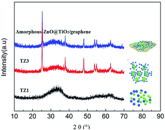
The crystal structures of the samples were investigated by XRD, as displayed in Fig. 1. The XRD patterns of the TZ1 samples exhibit a completely pure amorphous structure. For TZ3, all the diffraction peaks are attributed to anatase. Moreover, an obviously amorphous peak can be observed besides the characteristic peaks of anatase, implying the existence of an amorphous/crystalline composite structure. The amorphous/crystalline composite structure can also be found in the amorphous-ZnO@TiO2/RGO sample. There was no obvious peak of GO or RGO for the TiO2/RGO sample. This is because the lesser percentage of the crystalline phase of the carbon material cannot be distinguished from the background noise; this leads to a very weak XRD signal for the graphitic carbon.Fig. 2 shows the representative TEM images of the samples. The image of TZ1 shows an irregular shape of amorphous materials, and the inset SAED result confirms that the TZ1 sample is composed of amorphous particles, which is consistent with the XRD analysis. It can be seen that both the amorphous and crystalline phases coexist in the image of TZ3; this implies the existence of the amorphous-ZnO@TiO2 composite structure, which is confirmed by the inset SAED image and abovementioned XRD result. In the TEM images of the amorphous-ZnO@TiO2/RGO sample, it was observed that reduced graphene was rolled up into three-dimensional sheets and formed wrinkles, and the TiO2 nanoparticles were well dispersed and wrapped in the graphene sheets. The three-dimensional RGO nanoarchitecture provides a large intimate contact to amorphous-ZnO@TiO2; this maximizes the reaction. The intriguing structural design takes advantage of the synergetic effect between RGO and TiO2. This excellent contact enables the electrons to more easily transfer from TiO2 nanoparticles to graphene sheets during the photoexcitation process.
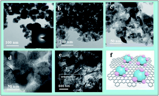 | ||
| Fig. 2 The TEM images of the prepared TZ1 (a), TZ3 (b)–(d), amorphous-ZnO@TiO2/RGO sample (e)–(f) and configuration model of the amorphous-ZnO@TiO2/RGO heterostructure. | ||
The N2 adsorption–desorption isotherms were measured to explore the textural properties and the porosity of the amorphous-ZnO@TiO2/RGO sample. As shown in Fig. 3a, the amorphous-ZnO@TiO2/RGO sample demonstrates the typical Type I isotherms, implying that it belongs to a kind of microporous material. The microporous area approximately accounts for 75% of the total pore surface area, which indicates that the amorphous-ZnO@TiO2/RGO sample has a higher microporous area, and its BET surface area is 336 m2 g−1. The pore size distributions were obtained via the density functional theory (DFT), as shown in Fig. 3b, and the amorphous-ZnO@TiO2/RGO sample has a main pore size distribution of 1.8 nm. Due to the low addition amount of graphene, the contribution of graphene to the total specific surface areas is negligible; thus, the existence of the amorphous structure is likely responsible for the large BET surface area of the sample.19
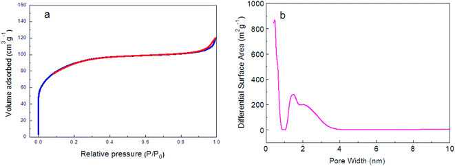 | ||
| Fig. 3 (a) N2 adsorption–desorption isotherms and (b) pore size distribution of the amorphous-ZnO@TiO2/RGO sample. | ||
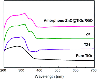
Fig. 4 shows the UV-vis absorption bands of the samples. The TZ1 sample with a pure amorphous structure shows one sharp edge at 336 nm. The TZ3 sample with an amorphous-ZnO@TiO2 composite structure has two absorption edges at 342 and 378 nm. With the introduction of graphene, the amorphous-ZnO@TiO2/RGO composites display a similar absorption edge as the TZ3 sample. The pure TiO2 shows one sharp edge at 370 nm. In general, anatase TiO2 shows no absorption above its fundamental absorption edge (around 400 nm). However, graphene can extend the broad background absorption of the sample in the visible-light region, and the sample changes from white to black after the introduction of graphene into the amorphous-ZnO@TiO2 composite structure. In contrast, for the TZ1 sample with a pure anatase structure, there is only one absorption peak present at 340 nm.
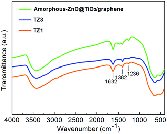
Fig. 5 shows the FTIR spectra of the prepared samples. The broad bands at 3400 and 1650 cm−1 can be ascribed to surface-adsorbed water and hydroxyl groups, respectively,36 which can act as photoexcited traps on the catalytic surface and produce hydroxyl radicals for oxidizing and degrading organics. There is no obvious change in the peaks of surface-adsorbed water and hydroxyl groups; this indicates that the variations of the crystalline structure have little influence on the two groups. The bands at 1400 and 1240 cm−1 can be assigned to the symmetric stretches of the Ti–O bond and Ti–OH bond, respectively.37,38 The bands at approximately 620 and 460 cm−1 are attributed to the vibration mode of the O–Ti–O band corresponding to the anatase crystalline phase.39,40
3.2 Enhanced photocatalytic properties
The photocatalytic activities of the as-prepared samples were evaluated through the degradation of MB and RhB under the irradiation of xenon lamp light, as shown in Fig. 6a and (b). The amorphous-ZnO@TiO2/RGO sample exhibits highest photocatalytic activity as compared to the other samples, indicating a positive influence on the photocatalytic MB decomposition due to the incorporation of graphene. Moreover, TZ3 also exhibits a high photocatalytic activity, which is even better than that of P25 and also much higher than that of the pure TiO2 and TZ1 samples. This indicates that the amorphous-ZnO/TiO2 composite structure can play an important role in the photocatalytic activity probably due to the adsorption and surface reactions that occur more easily on amorphous surfaces than on pure crystalline catalysts.32 Moreover, the TZ1 sample (pure amorphous phase) displayed low photocatalytic activity; this implied that a single amorphous structure did not function well. To further verify the photocatalytic performance of the samples, a comparative study of the degradation of RhB was also performed, and the photocatalytic activity of the sample for the degradation of RhB was similar to that for the degradation of MB. Both the amorphous-ZnO@TiO2/RGO sample and the TZ3 sample exhibited higher degradation rates for RhB, whereas the TZ1 sample demonstrated lowest photocatalytic activity.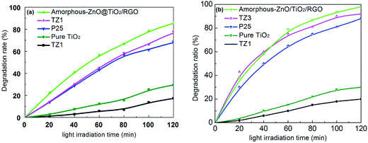 | ||
| Fig. 6 Photocatalytic activities of the as-prepared samples for the degradation of MB (a) and RhB (b). | ||
3.3 Mechanism analysis
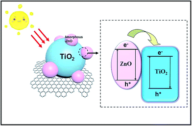
Based on the abovementioned results and analyses, the mechanism for the enhanced photocatalytic capacity of amorphous-ZnO@TiO2 composites can be explained, as shown in Fig. 7. First, amorphous-ZnO and TiO2 could synergistically improve the photocatalytic activity in the presence of simulated solar light. In general, it is thought that the amorphous phase cannot display high catalytic activity. Our previous study revealed that the sample with amorphous/crystalline composite structures could improve the photocatalytic activity,31 which was attributed to the highly active catalytic centers created by the synergistic effect of the amorphous/crystalline structures. There are numerous unsaturated sites on the surface of the amorphous-ZnO@TiO2/RGO heterostructure, which are in favor of the charge transfer and improve the separation of photogenerated electrons and holes. They also serve as an electron trap by capturing electrons, facilitating charge separation for the photocatalytic reaction. Second, the photoinduced electrons in the conduction band (CB) of TiO2 can be quickly transferred to graphene sheets41 because of the lower potential of graphene/graphene− (−0.08 V) as compared to those in the CB level of anatase TiO2 (about 0.24 V). Therefore, graphene can act as an electron transport mediator, facilitating the effective separation of the photogenerated electron–hole pairs and improving the photocatalytic activity. In addition, graphene could also be used as a 2D mat to increase the surface area and provide many adsorptive active sites to the photocatalyst, enhancing the photocatalytic activity. Therefore, for the degradation of MB and RhB, H2O and hydroxy (–OH) are absorbed by the holes (lattice defects) of the amorphous-ZnO@TiO2 and further form hydroxyl radicals (˙OH), and the holes can directly oxidize the contaminants into CO2 and H2O because of their strong oxidizability. The superoxide radicals and hydroxyl radicals can also participate in the reaction to degrade MB and RhB. TiO2 is the major catalyst for the photocatalytic decomposition of contaminants, and amorphous-ZnO serves as an electron trap by capturing electrons and facilitating charge separation for the photocatalytic reaction; however, RGO as an electron capture device accelerates the transfer of photogenerated charges, and the fast charge conduction along the graphene sheets helps the charge carriers to reach the redox sites, subsequently improving the photocatalytic activity. Therefore, the enhanced photocatalytic activity should be attributed to the synergy between the amorphous-ZnO@TiO2 heterostructure and RGO sheets.4. Conclusive remarks
In summary, a simple but efficient method has been developed for preparing a novel microporous amorphous-ZnO@TiO2/RGO heterostructure with higher photocatalytic activity and larger specific surface area. The amorphous-ZnO@TiO2 nanoparticles were uniformly loaded onto the surface of RGO. Compared to amorphous-ZnO and amorphous-ZnO@TiO2 composites, the ternary microporous amorphous-ZnO@TiO2/RGO demonstrated superior photocatalytic activity and stability for the degradation of the water pollutants, MB and RhB, in the presence of simulated solar light due to the synergy between graphene and the amorphous-ZnO@TiO2 heterostructure. This novel ternary structure is in favor of the charge transfer and improves the separation of photogenerated electrons and holes. These features can be expanded to other applications and open up new possibilities in the heterostructures of catalysts.Acknowledgements
The authors of this contribution gratefully acknowledge the support of the ongoing project of the National Natural Science Foundation of China (Contract No. 51420105015), 973 Program (Contract No. 2015CB655100) and 111 Program. This work was also supported by the National Natural Science Foundation of China (51508293), the National science foundation of China project (51478406), the Qingdao applied research project (17-1-1-87-jch), and the China Postdoctoral Science Foundation Funded Project (2016M600527). The first author also would like to acknowledge the fellowship support received from the Hong Kong Scholar Programme (G-YZ78).References
- Z. F. Jiang, W. M. Wan and W. Wei, Appl. Catal., B, 2017, 204, 283–295 CrossRef CAS.
- J. D. Milshtein, E. Gratz, S. N. Basu, S. Gopalan and U. B. Pal, J. Power Sources, 2013, 95–102 CrossRef CAS.
- S. Y. Guo, B. Chi, S. Han and J. Li, Mater. Res. Bull., 2013, 48, 3032–3036 CrossRef CAS.
- M. Carmo, D. L. Fritz, J. Mergel and D. Stolten, Int. J. Hydrogen Energy, 2013, 38, 4901–4934 CrossRef CAS.
- S. Y. Guo, B. Chi, S. Han and J. Li, J. Alloys Compd., 2012, 544, 50–54 CrossRef CAS.
- S. Pati, S. Gopalan and U. B. Pal, Int. J. Hydrogen Energy, 2011, 36, 152–159 CrossRef CAS.
- L. F. L. Oliveira, S. Laref and E. Mayousse, Phys. Chem. Chem. Phys., 2012, 14, 10215–10224 RSC.
- M. Carmo, T. Roepke, C. Roth and A. M. Dos Santos, J. Power Sources, 2009, 191, 330–337 CrossRef CAS.
- I. Lee, J. B. Joo, Y. D. Yin and F. Zaera, Angew. Chem., Int. Ed., 2011, 50, 10208–10211 CrossRef CAS PubMed.
- C. Xu, J. Zhu and R. Yuan, et al., Carbon, 2016, 96, 394–402 CrossRef CAS.
- M. Law, L. E. Greene, A. Radenovic, T. Kuykendall and J. Liphardt, J. Phys. Chem. B, 2006, 110, 22652–22663 CrossRef CAS PubMed.
- K. R. Reyes-Gil, C. Wiggenhorn and B. S. Brunschwig, J. Phys. Chem. C, 2013, 117, 14947–14957 CAS.
- D. K. Wang, M. Elma and J. Motuzas, et al., Carbon, 2016, 109, 182–191 CrossRef CAS.
- S. Y. Guo, B. Chi, S. Han and J. Li, ACS Appl. Mater. Interfaces, 2014, 6, 4743–4751 CAS.
- D. Wu, M. Yi and H. Duan, et al., Carbon, 2016, 108, 394–403 CrossRef CAS.
- J. Kuncewicz and B. Ohtani, RSC Adv., 2016, 6(81), 77201–77211 RSC.
- K. Pan, Y. Z. Dong and W. Zhou, ACS Appl. Mater. Interfaces, 2013, 5, 8314–8320 CAS.
- Y. K. Kim and S. M. Sharker, et al., Carbon, 2016, 103, 412–420 CrossRef CAS.
- A. Razzaq and C. A. Grimes, Carbon, 2016, 98, 537–544 CrossRef CAS.
- X. D. Hong, B. B. Zhang and E. Murphy, J. Power Sources, 2017, 343, 60–66 CrossRef CAS.
- R. Karthik, J. V. Kumar and S. M. Chen, ACS Appl. Mater. Interfaces, 2017, 9(7), 6547–6559 CAS.
- Q. Y. Long, G. Z. Ma and Q. Q. Xu, J. Power Sources, 2017, 343, 188–196 CrossRef CAS.
- J. H. Li, G. P. Zhang and C. P. Fu, J. Power Sources, 2017, 345, 146–155 CrossRef CAS.
- N. Zhang, Y. Zhang, X. Pan and M. Q. Yang, J. Phys. Chem. C, 2012, 116, 18023–18031 CAS.
- S. W. Liu, C. Liu and W. G. Wang, Nanoscale, 2012, 4, 3193–3200 RSC.
- X. F. Zhang, X. Quan and S. Chen, Appl. Catal., B, 2011, 105, 237–242 CrossRef CAS.
- Z. Xiong, L. L. Zhang and J. Ma, Chem. Commun., 2010, 46, 6099–6101 RSC.
- I. Y. Kim, J. M. Lee, T. W. Kim and S. J. Hwang, Small, 2012, 8, 1038–1048 CrossRef CAS PubMed.
- H. Cao and S. L. Sui, J. Am. Chem. Soc., 1994, 116, 5334–5342 CrossRef CAS.
- J. M. Yan, X. B. Zhang, S. Han and H. Shioyama, Angew. Chem., Int. Ed., 2008, 47, 2287–2289 CrossRef CAS PubMed.
- S. Y. Guo, B. Chi, S. Han and J. Li, J. Power Sources, 2014, 245, 979–985 CrossRef CAS.
- B. Ohtani, Y. Ofawa and S. I. Nishimoto, J. Phys. Chem. B, 1997, 101, 3746–3752 CrossRef CAS.
- Y. Xu, H. Bai, G. Lu and G. Shi, J. Am. Chem. Soc., 2008, 30, 5856–5857 CrossRef PubMed.
- L. Yang, J. Kong, W. A. Yee and W. Liu, Nanoscale, 2012, 4, 4968–4971 RSC.
- X. Yan, Y. J. Li and F. Du, Nanoscale, 2014, 6, 4108–4116 RSC.
- T. Ivanova, A. Harizanova and T. Koutzarova, J. Non-Cryst. Solids, 2011, 357, 2840–2845 CrossRef CAS.
- X. T. Wang, S. H. Zhong and X. F. Xiao, J. Mol. Catal. A: Chem., 2005, 229, 87–93 CrossRef CAS.
- Y. Xie, X. Liu, A. Huang, C. Ding and P. K. Chu, Biomaterials, 2005, 26, 6129–6135 CrossRef CAS PubMed.
- S. Music, M. Gotic and M. Ivanda, Mater. Sci. Eng., B, 1997, 47, 33–40 CrossRef.
- M. Ocana, V. Fornes and J. V. Serna, J. Solid State Chem., 1988, 75, 364–372 CrossRef CAS.
- H. Lei, W. Ping and S. Dong, Nanoscale, 2012, 4, 5814–5825 RSC.
| This journal is © The Royal Society of Chemistry 2017 |

