 Open Access Article
Creative Commons Attribution 3.0 Unported Licence
A high-resolution passive droplet-phase sample sorter using multi-stage droplet transfer†
D. H. Yoon *a,
Z. Xiea,
D. Tanakab,
T. Sekiguchib and
S. Shojia
aFaculty of Science and Engineering, Waseda University, 3-4-1, Okubo, Shinjuku-ku, Tokyo, 169-8555, Japan. E-mail: yoon@shoji.comm.waseda.ac.jp
bResearch Organization for Nano & Life Innovation, Waseda University, 513, Tsurumaki-cho, Waseda, Shinjuku-ku, Tokyo, 162-0041, Japan
First published on 25th July 2017
Abstract
A fully passive volume-dependent droplet sorter is presented in this research. Repeated and multiple on-rail transfer of microdroplets in a cascade channel resulted in high resolution sorting of droplet-phase samples. Microdroplets with volumes of 0.89–3.26 nl were successfully sorted in eight steps, and a maximum sorting resolution of about 0.21 nl was obtained over three transfer stages. Line rails and dot rails employed in the cascading channels allowed volume-dependent droplet transfer, and shape recovery of the transferred droplet for the repeatable transfer, respectively. This simple device and method can be applied to droplet-based chemical or biological research.
Introduction
Droplet-based microfluidics has been widely studied because it can realize fast and precise biochemical reactions.1,2 Many researchers have attempted to control the small volumes of samples using droplets, and hydrodynamic structures have provided uniform and well-defined droplet volumes.3,4However, recent droplet employing research has required multi-step manipulations using various materials and functional elements in a single chip.5–9 The complex manipulation results in increased instability of the droplet generation due to internal flow disturbance or a non-uniform droplet volume due to specific target encapsulation. For instance, the droplet volume can be changed by a change in the flow resistance10 with the operation of other elements in a multi-functional integrated system. Moreover, cell encapsulated droplets exhibit wide volume rages depending on the number of cells or volume ratio of the cell and droplet.11
The droplet sample's volume and volume uniformity is crucial for the precision and reliability of the research, thus the collection or rejection of target samples that have specific droplet volumes is required in a functional system.12,13 The classification of samples by volume would have high potential for the chemical applications using droplets. Because controlled volumes of droplet-phase samples can be mixed, reacted, and analyzed, we can obtain better quantification of the experimental results. Moreover, the number of cells in a droplet is one of the critical issues for cell analysis research; if the volume of droplets containing a specific number of cells is different than that of other droplets and we can sort them, the experimental efficiency and reliability of the research could increase dramatically.
Fundamentally, droplet sorting requires a detection of the difference between target and non-target, and hydrodynamic switching. In the case of active systems, the targets are detected by an optical or electrical method, and they are separated by an optical, thermal, mechanical, or electrical switching system.14–19 These methods allow fast switching and high throughput, but the requirements of a complex system and operation are burdensome on devices that already require integration with other components. Therefore, a simple passive method is necessary and suitable for various types of applications.
Passive hydrodynamic sorting methods employ lateral flows that differ in direction from the main stream. For instance, deterministic lateral displacement,20,21 Dean flow in a curved channel,22,23 and flow fractionation24–28 are the representative volume-dependent passive sorting methods. Whether it is using obstacles in the channel or channel geometry or additional flow, the principle of droplet sorting of different volumes is basically the same. Droplets in the main flow are pushed by the side flow using one of the methods mentioned above, and the drag behaviors of droplets are changed depending on their volume or size. However, a long channel is necessary for this probability-dependent sorting and, unlike particles and cells, flexible droplets may be broken by the obstacles in the channel, depending on the droplet volumes and flow conditions. In addition, while simple separation is possible, it is difficult to accurately sort the droplets into various volume steps because flow-based methods require well-defined flow conditions and pre-positioning of the droplet samples.
In contrast, we reported a fully passive and highly accurate droplet sorting method using a rail-like channel structure.29 Droplets were simply guided on a rail and those of target size were selectively transferred to other rails. The droplets were sorted into a maximum of five steps on the serial rails. However, the serial rails allowed only single-stage sorting, and the sorting results were affected by the other rails. In addition, the change in droplet pitch due to flow loss to the other rails caused experimental errors in practice. Therefore, the ability to increase the sorting resolution and steps has been limited.
Hence, we proposed parallel rails to increase the droplet sorting resolution and steps, and investigated a method for repeatable droplet transfer in the rails.
Principle
Multi-stage droplet transfer
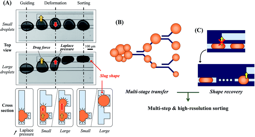
The principle of on-rail droplet transfer is shown in Fig. 1(A). Because of Laplace pressure in the microchannel, introduced droplets can move along the rail way.29,30 In the flow field, when a new rail appears downstream, lateral flow into the new rail occurs and the droplet deforms to that direction. The droplet reaches the new rail and is newly influenced by Laplace pressure if it is large or deformed enough. If the Laplace pressure of the droplet on the new rail is lower than that on the old rail, the droplet transfers to the new rail completely. Therefore, the distance between the two rails determines the threshold transfer size or volume of the droplets.To increase the sorting resolution and steps, many and different rail distances are necessary. However, rail positions that are too close or too many rails in a small area influence lateral flows of the other rails. Therefore, the pair rails should be located in an area independent from the others.
The cascading rail design satisfies the requirements of independent positioning of sorting rails and high resolution, with multiple sorting steps via repeatable droplet sorting in multiple stages. The droplets sorted into two steps in the first stage are sorted again into four steps in the second stage. The repeated sorting enhances the sorting resolution and steps simply, as shown in Fig. 1(B). In this research, a total of three stages were employed for eight steps of droplet sorting.
Droplet shape recovery for multiple sorting transfers
Unfortunately, the droplets transferred onto the new wide rails change to a slug-like shape, as shown in Fig. 1(C). The altered shape is no longer useful for the droplet transfer, thus the shape recovery of the droplets is a preliminary task for the repeated droplet transfer. Because the shape change is caused by Laplace pressure, and the channel width of the old rail is suitable to predict the threshold volume of transferred droplets, the large channel width was decreased to the same width as the old rails before the next sorting stage. However, continuous width reduction using a nozzle-like rail shape did not restore the droplet shape. We considered that a gradual change in the rail geometry was not enough for the shape recovery with respect to the dynamic deformation of the droplet and hydrodynamic pressure. Therefore, the temporary disconnection of the rail was necessary for a perfect shape recovery. In addition we employed a dot rail as a part of the development of a new functional droplet guiding geometry along with the conventional line rails. The dot rail not only contributed to the shape recovery of droplets, but was also expected to be effective in guiding the droplet route. Therefore, we used this new geometry for the disconnected area between the rails of different width.Experimental
Computational analysis
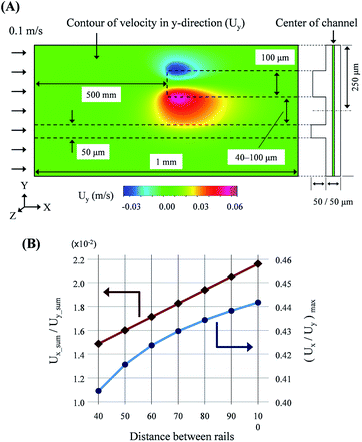
As mentioned above, the droplet transfer is initiated from the deformation of the droplets due to the side flow into the new rail. Thus, the strength of the side flow is the most critical value in determining the threshold volume of the droplet transfer. The side flow was calculated using computational analysis (CFD-ACE+, ESI Group), as shown in Fig. 2(A). The widths of the old rail, new rail, and channel were 50, 100, and 500 μm, respectively, and the height of the rail and channel layer was 50 μm. The distance between the old and new rail ranged from 40 to 100 μm at intervals of 10 μm. The calculation mode was “Flow” and the properties of water were used for the calculation. The velocity in the normal direction at the inlet boundary was 0.1 m s−1 and the results were calculated at all positions in the domain shown in Fig. 2(A). | ||
| Fig. 2 Results of computation analysis for the rail structure: (A) conditions of the analysis and visualization of the flow field. (B) Quantitative evaluation of the side flow onto new rail. | ||
As shown in Fig. 2(B), a ratio of the sum of the velocities in the y- and x-direction at the center of the channel layer was linearly increased via an increase in the distance between the two rails. Furthermore, the maximum ratio of the transverse and longitudinal flow, Uy/Ux, in the field also increased with the distance increment. Therefore, we believed that high resolution and multi-step droplet sorting would be possible using rails of various distances.
Device design
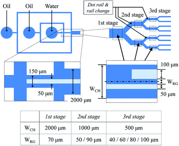
The total device consists of two parts for droplet generation and sorting, as shown in Fig. 3. The droplets are generated in a cross channel, and their pitch and flow velocity are controlled by a flow from an additional sheath channel. The rail begins at the generation part, and the three-stage cascading channel and rail pairs are located downstream. The height of the channel and rail layer is 50 μm, and the widths of old and new rail of each rail pair are 50 and 100 μm, respectively. The distance between the old and new rails ranges from 40 to 100 μm at intervals of 10 μm. The diameter and pitch of the dot rail are 50 and 75 μm, respectively.Device fabrication
The device was fabricated with a soft lithography process using a photoresist mold (SU-8, Microchem) and PDMS (Silpot 184, Dow Corning). The channel and rail layers were formed by a two-layer SU-8 mold. After an O2 plasma treatment (Aiplasma, Matsushita Electric Works), the PDMS structure was bonded onto a PDMS spin-coated glass substrate to obtain the fully enclosed PDMS device.Experimental setup and materials
In this study, syringe pumps (KDS210, KD Scientific) were used for liquid injection, droplet generation, and sorting in the device and system. Salad oil was used as the carrier fluid, and the droplets were water. Flow rates of the oil and water to generate various droplet volumes were widely ranged, but the total volumetric flow rates into the device were fixed to 25 μl min−1. The droplet generation and sorting behavior were visualized with a high-speed camera (FASTCAM-NEO, Photron). The droplet volumes were calculated by pixel counting for the droplets in the main channel.Results and discussion
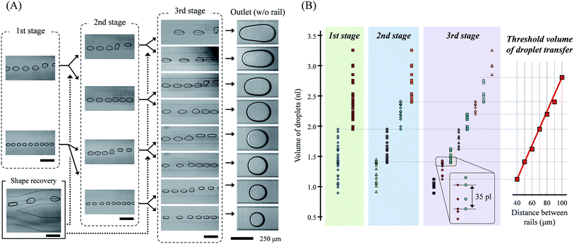
By the three-stage droplet transfer, droplets of different volumes were successfully sorted, as shown in Fig. 4. Each rail pairs transferred the droplets onto different rails corresponding to their distance and droplet volumes. The slug-shape of the droplets due to their transfer onto a new rail, which interrupted additional transfers at the next rail pairs, was converted back to the circular shape at the dot-rail. The dot-rail guided the droplet route well, even if the broken rail distance was long and the route direction was different than the flow. These two important functional elements allowed the droplets' parallel and repeated sorting. Droplets were divided into specific volume ranges in the previous rail pair, and the range was divided more precisely in the next rails. Thus, we could obtain eight-step sorted droplets in a single device, and we believe that the number of sorting steps can be increased via an increase in the sorting stages.As mentioned in the computational analysis section, the transferrable threshold volume of the droplets was determined by the distance between the rails. The threshold volume of the transferred droplets changed almost linearly with the distance between the rails, as shown in Fig. 4(B). Comparing the simulated and experimental results, it appears that the transfer of the droplet is related to the sum of the total lateral flow in the field, not the maximum velocity of the lateral flow.
The minimum and maximum volume range of the droplets sorted in the cascade rails at intervals of 10 μm was about 213 and 357 pl, respectively. The total volume range of the droplets in this study was 0.89–3.26 nl, and it is expected that droplets smaller than 0.89 nl and larger than 3.26 nl will be sorted into rail pairs of 50 μm and 100 μm, respectively. Furthermore, the maximum error range in which the volumes of droplets sorted by different rails overlap each other was 35 pl in the experiments. In addition, even when mixed droplets of different sizes are introduced simultaneously, the droplets were successfully sorted into different rails (see ESI† movie).
The sorting range is high enough, but it is partially shifted. We conclude that the result is not only an experimental error, but also due to the change in the side flow caused by different channel geometries in each stage. We designed the channel width of the previous stage to be twice that of the next stage to obtain the same flow speed and droplet pitch in all stages. Therefore, it seems that the near or far channel wall influenced the side flow, and the difference caused a change in the threshold volume.
In addition, the dimensions of a rail pair are an interesting parameter. In this research, we used rails of 50 and 100 μm in width for the old and new rail. A wide new rail will increase the volumetric flow rate of the side flow and a wide old rail will decrease the flow. The aspect ratio of the rail and the height of the channel are also considerations. A narrow and shallow rail structure, compared to the channel height, prevents the droplets from getting stuck in the rail groove because of high Laplace pressure. However, comprehensive consideration of the hydrodynamic condition such as velocity and Laplace pressure is necessary for the modification.
Conclusions
In this study, high resolution sample sorting using on-rail droplet transfer was presented. Cascading channels employing rail pairs and dot-rails allowed multiple and repeated droplet transfer, thus multi-step droplet sorting was obtained. Droplets with volumes on the order of nano/picoliters were successfully sorted, and a maximum volume resolution of about 200 pl was obtained in the three sorting stages. We also demonstrated that the droplets recovered their round shape and were guided on the dot-rails. Furthermore, the number of stages and distance between pair rails were related to the sorting precision and resolution.The proposed structure is a useful module as a passive actuator or self-triggered switch. Without any additional flow control or manipulation, the droplets' position can be simply guided before and after sorting, with the rail pairs changing their routes based on the physical properties of the droplets and hydrodynamic features. We believe this module will not only realize a wide volume range of droplet collection and classification as an independent sorting device, but also be an important element that could be simply integrated with other functional elements. Thus, it will provide more effective and wide exploration opportunities to droplet-based chemical and biological research.
Acknowledgements
This work is partly supported by Japan Ministry of Education, Culture, Sports Science & Technology (MEXT) Grant-in-Aid for Scientific Basic Research (A) No. 16H02349. And the authors thank for MEXT Nanotechnology Platform Support Project of Waseda University.References
- B. E. Debs, R. Utharala, I. V. Balyasnikova, A. D. Griffiths and C. A. Merten, Proc. Natl. Acad. Sci. U. S. A., 2012, 109, 11570–11575 CrossRef PubMed.
- B. Zheng, J. D. Tice, L. S. Roach and R. F. Ismagilov, Angew. Chem., Int. Ed., 2004, 43, 2508–2511 CrossRef CAS PubMed.
- X. C. I. Solvas and A. deMello, Chem. Commun., 2011, 47, 1936–1942 RSC.
- S. Seiffert and D. A. Weitz, Soft Matter, 2010, 6, 3184–3190 RSC.
- R. K. Isgor, M. Marcali, M. Keser and C. Elbuken, Sens. Actuators, B, 2015, 210, 669–675 CrossRef.
- G. Luca, A. Ahmadi, H. Najjara, E. Alocilja, M. DeRosa, K. Wolthers, A. Malki, H. Aziz, A. Althani and M. Hoorfar, Sensors, 2015, 15, 30011–30031 CrossRef PubMed.
- G. M. Whitesides, Nature, 2006, 442, 368–373 CrossRef CAS PubMed.
- A. D. Griffiths and D. S. Tawfik, Trends Biotechnol., 2006, 24, 395–402 CrossRef CAS PubMed.
- L. Mazutis, J. Gilbert, W. L. Ung, D. A. Weitz, A. D. Griffiths and J. A. Heyman, Nat. Protoc., 2013, 8, 870–891 CrossRef CAS PubMed.
- C. T. Riche, E. J. Roberts, M. Gupta, R. L. Bruchey and N. Malmstadt, Nat. Commun., 2016, 7, 10780 CrossRef CAS PubMed.
- M. Chabert and J.-L. Viovy, Proc. Natl. Acad. Sci. U. S. A., 2008, 105, 3191–3196 CrossRef CAS PubMed.
- D. T. Chiu and R. M. Lorenz, Acc. Chem. Res., 2009, 42, 649–658 CrossRef CAS PubMed.
- N. Shemberkar, C. Chaipan, R. Utharala and C. A. Merten, Lab Chip, 2016, 16, 1314–1331 RSC.
- D. R. Link, E. Grasland-Mongrain, A. Duri, F. Sarrazin, Z. Cheng, G. Cristobal, M. Marquez and D. A. Weitz, Angew. Chem., Int. Ed., 2006, 45, 2556–2560 CrossRef CAS PubMed.
- C. N. Baroud, J.-P. Delville, F. Gallaire and R. Wunenburger, Phys. Rev. E: Stat., Nonlinear, Soft Matter Phys., 2007, 75, 046302 CrossRef PubMed.
- L. Wu, P. Chen, Y. Dong, X. Feng and B.-F. Liu, Biomed. Microdevices, 2013, 15, 553–560 CrossRef CAS PubMed.
- F. Guo, X.-H. Ji, K. Liu, R.-X. He, L.-B. Zhao, Z.-X. Guo, W. Liu, S.-S. Guo and X.-Z. Zhao, Appl. Phys. Lett., 2010, 96, 193701 CrossRef.
- M. R. de Saint Vincent, R. Wunenburger and J.-P. Delville, Appl. Phys. Lett., 2008, 92, 154105 CrossRef.
- A. R. Abate, J. J. Agresti and D. A. Weitz, Appl. Phys. Lett., 2010, 96, 203509 CrossRef.
- H. N. Joensson, M. Uhlen and H. A. Svahn, Lab Chip, 2011, 11, 1305–1310 RSC.
- J. McGrath, M. Jimenez and H. Bridle, Lab Chip, 2014, 14, 4139–4158 RSC.
- E. W. M. Kemna, R. M. Schoeman, F. Wolbers, I. Vermes, D. A. Weitz and A. van den Berg, Lab Chip, 2012, 12, 2881–2887 RSC.
- D. H. Yoon, J. B. Ha, Y. K. Bahk, T. Arakawa, S. Shoji and J. S. Go, Lab Chip, 2009, 9, 87–90 RSC.
- H. Maenaka, M. Yamada, M. Yasuda and M. Seki, Langmuir, 2008, 24, 4405–4410 CrossRef CAS PubMed.
- Y.-C. Tan, J. S. Fisher, A. I. Lee, V. Cristini and A. P. Lee, Lab Chip, 2004, 4, 292–298 RSC.
- A. C. Hatch, A. Patel, N. R. Beer and A. P. Lee, Lab Chip, 2013, 13, 1308–1315 RSC.
- C.-H. Yang, Y.-S. Lin, K.-S. Huang, Y.-C. Huang, E.-C. Wang, J.-Y. Jhong and C.-Y. Kuo, Lab Chip, 2009, 9, 145–150 RSC.
- Y.-C. Tan and A. P. Lee, Lab Chip, 2005, 5, 1178–1183 RSC.
- D. H. Yoon, S. Numakunai, A. Nakahara, T. Sekiguchi and S. Shoji, RSC Adv., 2014, 4, 37721–37725 RSC.
- P. Abbyad, R. Dangla, A. Alexandrou and C. N. Baroud, Lab Chip, 2011, 11, 813–821 RSC.
Footnote |
| † Electronic supplementary information (ESI) available. See DOI: 10.1039/c7ra05556k |
| This journal is © The Royal Society of Chemistry 2017 |


